The EIP 545A Microwave Frequency Counter is a relatively small frequency counter useful for frequencies from 10 Hz to 18 GHz.
It has three separate inputs, 10 Hz to 100 MHz, 100 MHz to 1 GHz, and 1 GHz to 18 GHz, the first two with BNC connectors and the last with a N connector.
Further, it has several options that are useful for various applications including Option 02 which is a RF power meter on the 1 GHz to 18 GHz input, Options 03 - 05 which are various OCXO time base options, and Option 08 that is a GPIB option.
I have been assembling equipment for a workshop and came into possession of a 545A that had Options 02, 03, 08, and Option W-29, which remains a mystery. As I try to do, I obtained a second unit as a 'spare' and potential parts donor that had only Option 03.
In addition, I obtained a 545 that was a 'pieces' unit, clearly a parts donor, that shares several parts in common with the 545A. I make a habit of doing this for vintage equipment due to the certainty of eventual parts failure and the problems of obtaining replacement parts.
I became interested in acquiring the skills to archive the EPROM data contained in this and other equipment as well as the possibility of adding options to my 'spare' 545A. The GPIB option needs a separate GPIB board but the RF power meter option appeared to be a simple matter of modifying an existing board and adding the needed software support contained in the EPROMs of my original 'reference' 545A.
If successful, the 'target' 545A would have Option 02.
This document reports the specific steps needed to add Option 02 to an EIP 545A along with the EPROM data contained in these three units. Hopefully, this will be helpful to someone in the future for maintenance of their units and allow someone to add an useful option as well.
The RF power meter option primarily resides on the A107 board. It is controlled by the A105 board and, therefore, EPROM changes are needed on the A105 board.
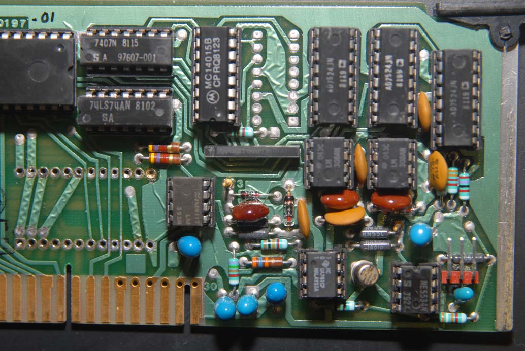
The picture below shows the comparison of an A107 board between a unit with (top) and without (bottom) the RF power meter option:
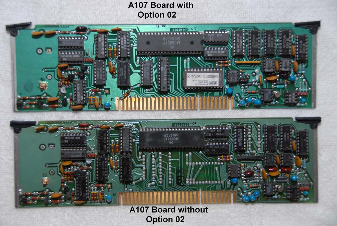
The PC boards are identical. However, the top board has four additional ICs along with several slight modifications in the parts that are installed.
The 'reference' 545A is CCN 2204, SN 01835. The 'target' 545A is CCN 2203, SN 00535.
I have been able to locate manuals for the 545A, one with part number 5580021-03, November 1981, with updates that allow the manual to function for CCN 2202 and CCN 2203, as well as part number 5580021-04, April 1983, CCN 2205. The CCN 2203 manual appears to accurately reflect both my 545As and is the reference used for this report.
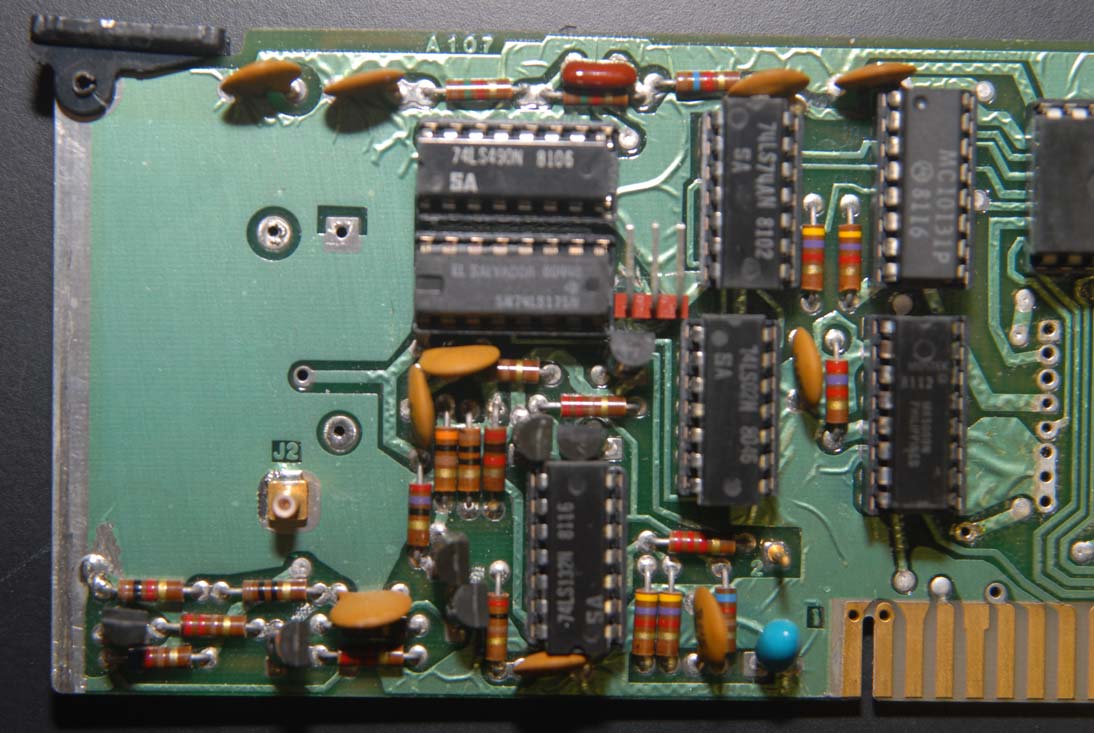
The differences between the A107 boards are further highlighted in the following pictures:
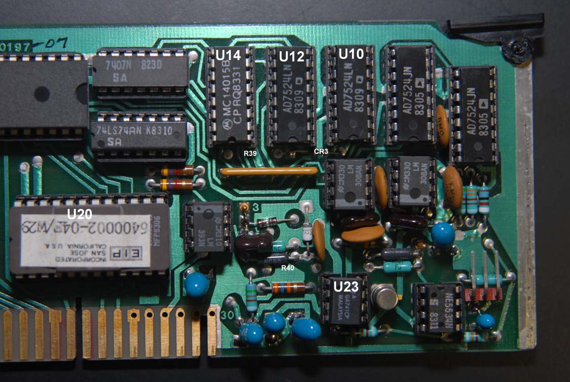
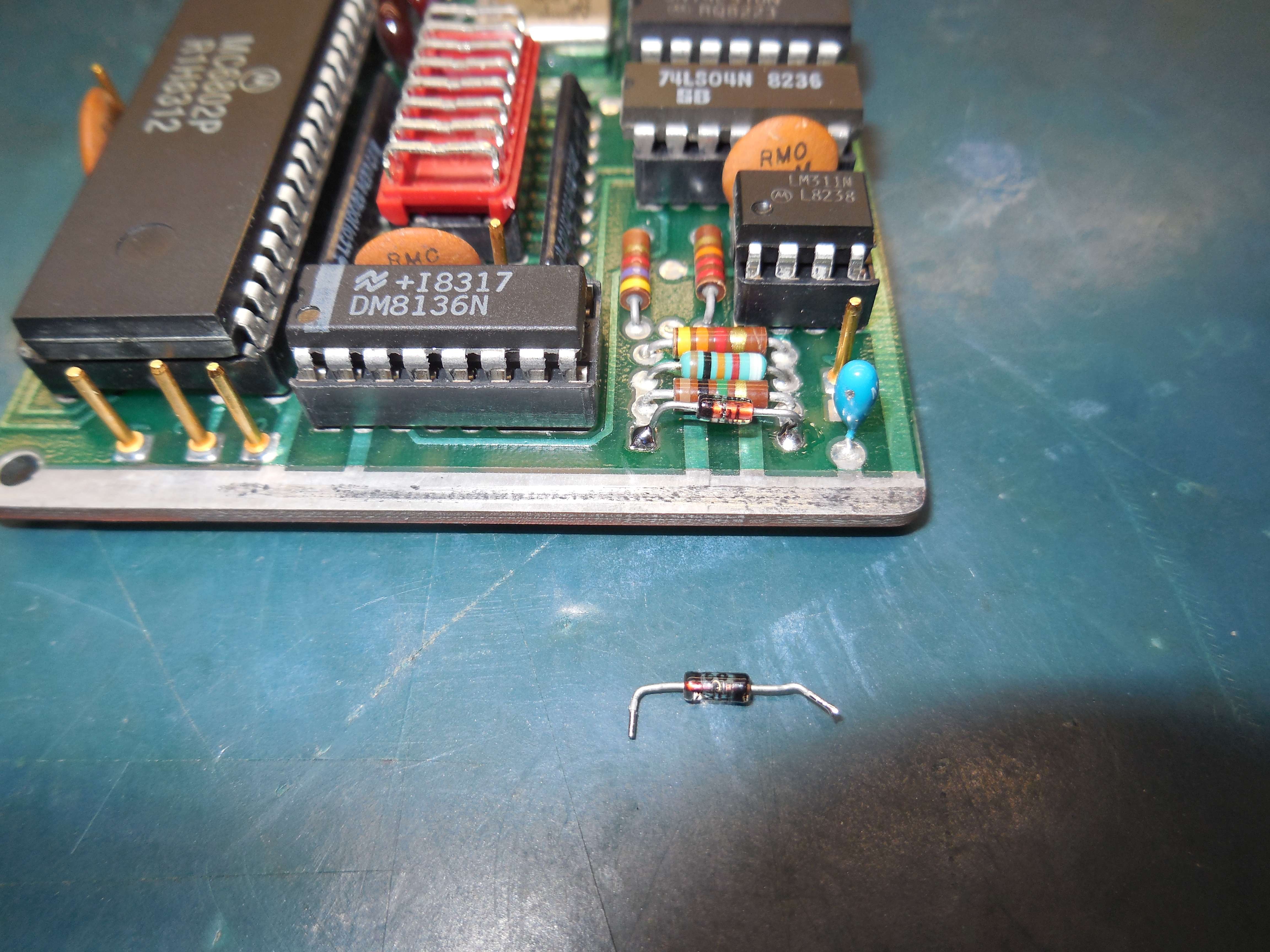
The picture above shows that this board has an additional AD7524LN (U12) and an additional EPROM, a TMS2516JL-45 (U20) installed as well as a diode, a FH1100 (CR3) installed just below U12 and between U12 and U10. The diode is 'pointed' toward U12.
Further, R39 and R40, two 10 kΩ resistors, are missing on this board compared with the board below. R39 is located below and between U14 and U12 and R40 is located slightly above and to the left of U23.
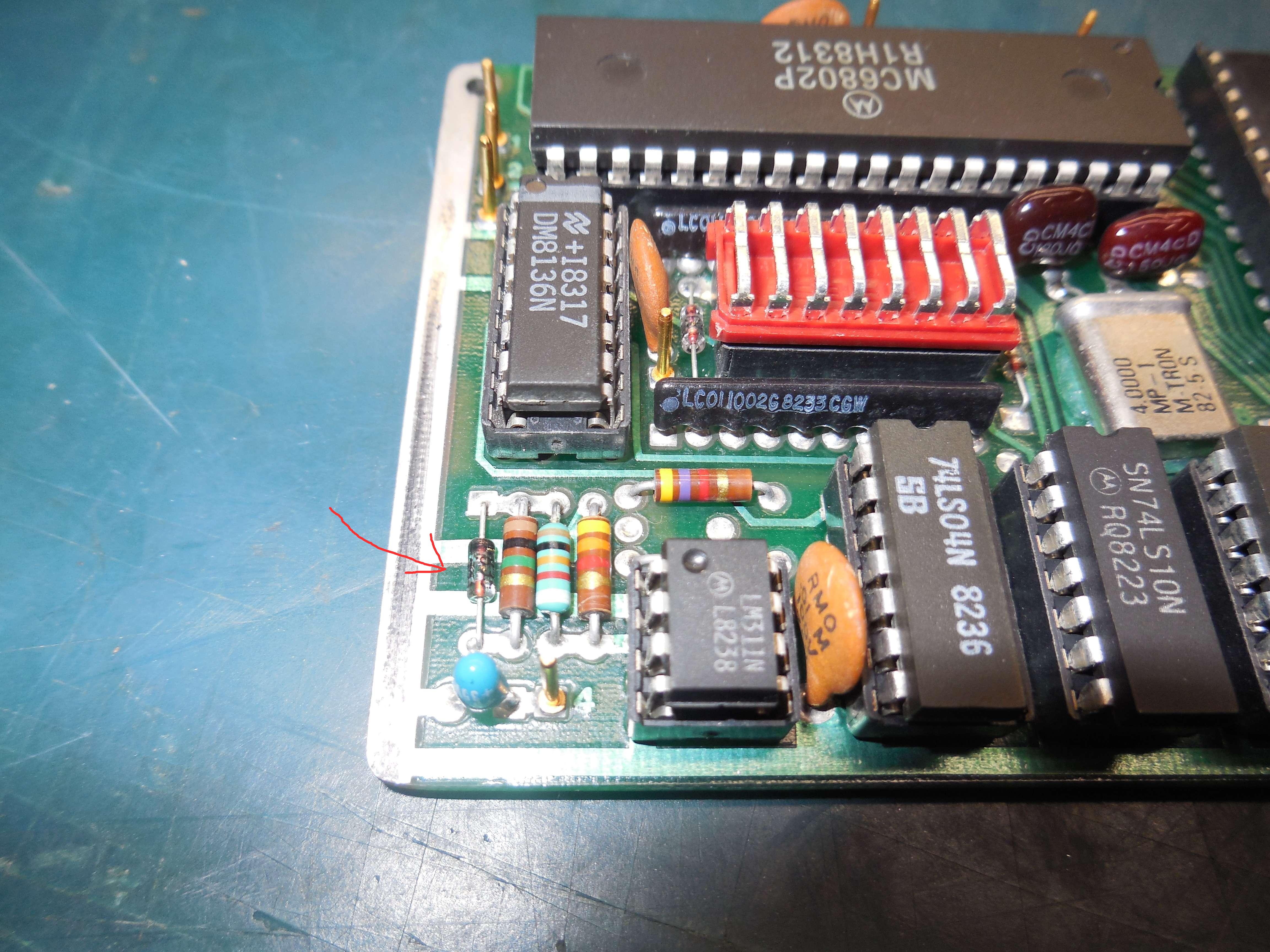
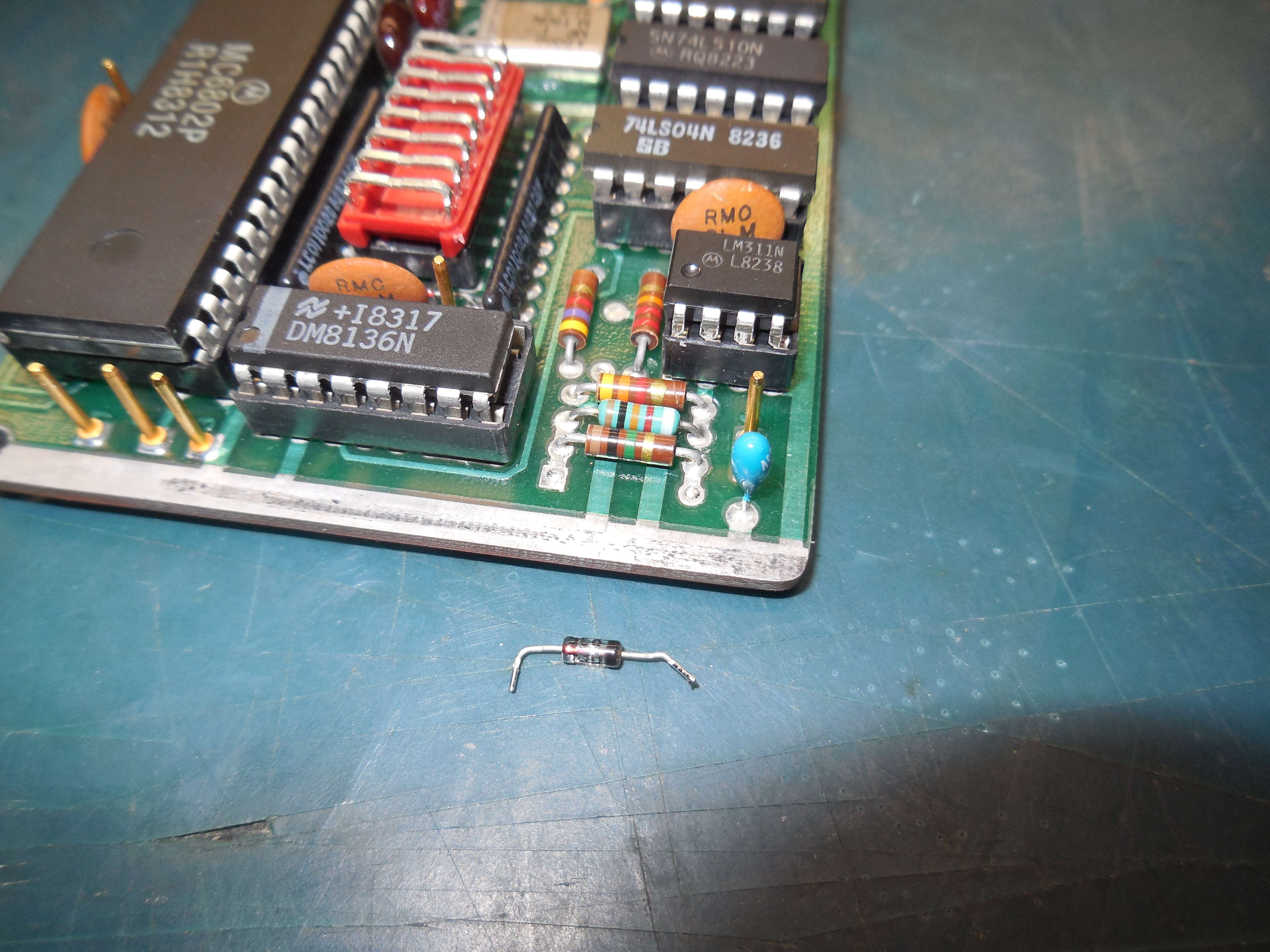
Pierre, F5BQP, suggested using a HP 5082-9496 Schottky barrier diode in place of the FH1100, a HP 5082-2835 (Agilent) hot-carrier diode. I had the 5082-9496 diode on the shelf, used it, and it seems to work O.K.
Editor's Note: You can salvage a proper FH1100 (or HP 5082-2835) hot-carrier diode from the A105 CPU board (CR1). It's on the far left-hand of the board, just below the CPU and is used for the power-on reset circuit. CR1 can be replaced with a 1N5711 or even common 1N914.
- Picture #1
- Picture #2 CR1 diode is labeled "HP2835-321" which should be equivalent to a "5082-2835" now.
- Picture #3 You can replace CR1 with a 1N914.
The picture below is the 'target' A107 board, pointing out the different components needed to be installed and components needed to be removed:
The picture below further illustrates the differences between the 'Option 02' A107 board and the 'non-Option 02' A107 board:
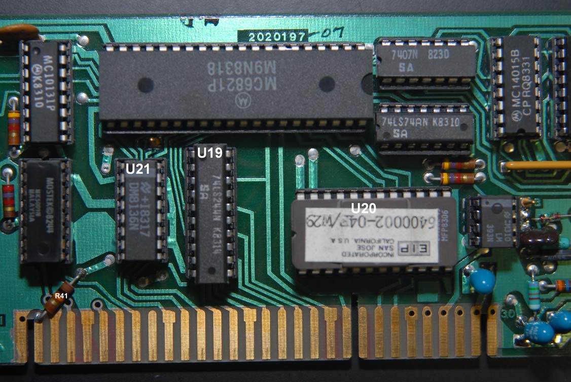
The picture above shows the EPROM (U20) along with additional ICs, a 74LS244N (U19) and a DM8136N (U21), along with an additional 10 kΩ resistor (R41):
These changes constitute the significant changes between these boards.
All ICs are socketed and I was able to find new chips from current suppliers and/or the surplus markets.
There were additional differences between the boards having to do with the value of resistors R24, R25, and R26 which did not seem to affect operation.
The parts list relates that R24 and R25 should be the same, 1.5 kΩ, and R26 should be 1.6 kΩ.
These resistors are located at the upper-left edge of the PC board, left to right.
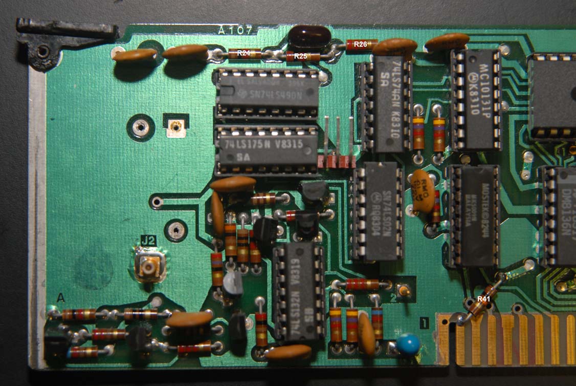
The Option 02 board, above, R24 is 1 kΩ, R25 is 2 kΩ and R26 is 2.2 kΩ while below, the values are as spec'd.
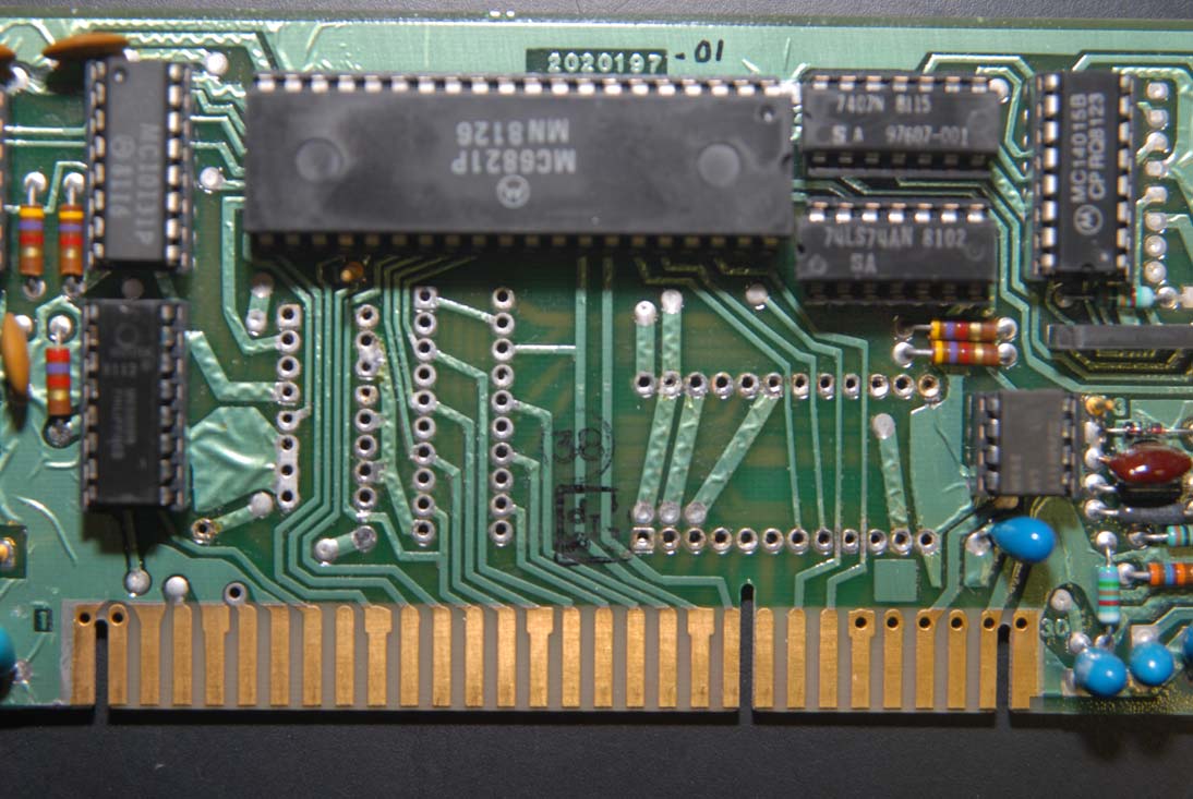
The A105 board had only EPROM differences. Otherwise, the boards were identical:
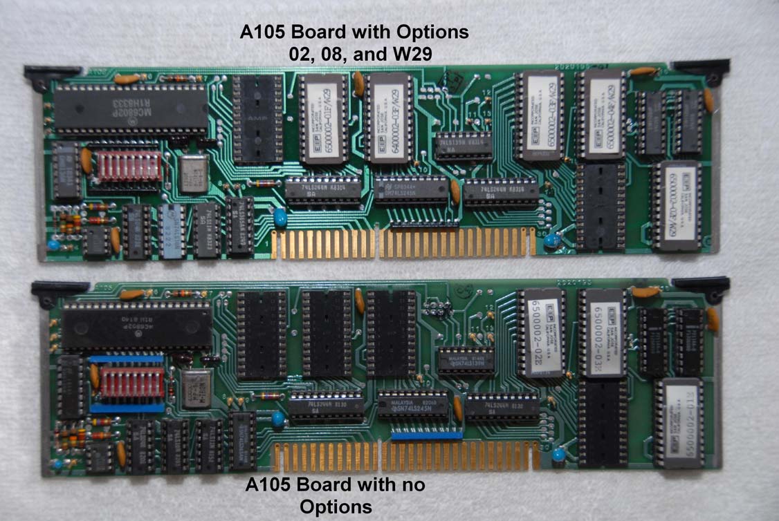
The EPROMs on the A105 board are TMS2532JL-45s with the exception of 6400002-03F/W29 which is a TMS2516JL-45, the same type as on the A107 board.
I was able to read, archive, and duplicate the EPROMs from the A105 board of both the 'reference' 545A and the 'target' 545A as well as the EPROM from the A107 board of the 'reference' 545A.
I then made the modifications to the 'target' A107 board, installed the new set of EPROMs on the 'target' A105 board as well as the EPROM on the 'target' A107 board.
Please note the locations of the various EPROMs on the A105 board WITH options versus the A105 board WITHOUT options. The EPROMs "move around." For instance, 6500002-01E is at the lower-right corner on the board WITHOUT options while 6500002-01F/W29 is top-row, far-left, on the board WITH options.
Once the boards were installed in the 'target' 545A, it now had Option 02.
I did not try moving the GPIB board see if it, too, worked, but I suspect it would. I have subsequently discovered that my 'target' 545A had a pre-existing problem in that it would not reliably read the correct frequency and some frequencies it would not read at all.
Therefore, I have been unable to complete the calibration of the power meter option in the 'target' 545A. Since the A201 units are different between the two 545As, a calibration of the 'target' 545A is required, as outlined in the 545A manual, and would appear to require at least a very long weekend (50 MHz steps from 1 GHz to 18 GHz as well as various power settings). I will be doing that once I get the 'target' 545A repaired. It will require making a copy of the U20 EPROM from the A107 board then 'blanking' several addresses, making measurements of the signal applied from a signal generator with a power meter, then reprogramming the EPROM to 'install' these values and continuing on until completion.
In order to 'test' my modification, I made some measurements with my 'reference' 545A, with it's original A105 and A107 boards installed, then installed the 'target' 545A's modified A105 and A107 boards in the 'reference' 545A and repeated the measurements. The results of these measurements follow.
The test was conducted using an HP8672A signal generator with both the HP8672A and the EIP 545A fed with an external reference, my shop standard frequency reference, an HP Z3816A GPSDO, feeding several HP5087A distribution amplifiers. I chose frequencies from 2 GHz to 18 GHz, at 1 GHz steps, with amplitudes from -30 dBm to 0 dBm, at 10 dBm steps at each frequency, as determined by my HP8672A. The HP8672A was connected to the 545A by a three foot section of Belden 9913F7 coax that I installed type-N connectors on.
This test assumes that the output amplitude delivered to the 545A is stable over time and frequency and no independent measurement of the signal delivered was made. Rather, the results of the two sets of measurements are compared against each other to 'verify' the accuracy of the modification. Some 'random second measurements' were made to investigate the assumption that the output was stable over time and are shown in parenthesis above their respective initial measurements. All measurements were made after the frequency readout was accurate, stable, and then there were two consecutive stable power measurements, typically the first two or three measurements. The results are below:
'Reference' 545A with:        'Reference' Boards Installed             'Target' Boards Installed

HP8672A Amplitude (dBm):      -30.0   -20.0   -10.0   +0.0            -30.0   -20.0   -10.0   +0.0
Freq (GHz)
---------------------------------------------------------------------------------------------------
2                             -29.5   -19.7    -9.9   +0.3            -29.8   -19.6    -9.9   -0.2
3                             -30.0   -19.9   -10.1   -0.7            -30.3   -20.0   -10.3   -0.2
4                             -29.0   -19.0    -9.3   +2.0            -29.2   -19.1    -9.4   +2.0
                                              (-10.0)                                 (-10.2)
5                             -29.6   -19.7    -9.9   -0.2            -29.7   -19.9    -10.0  +0.0
6                             -29.7   -19.9   -10.2   -0.1            -29.8   -20.0    -10.2  -0.1
7                             -30.2   -20.3   -10.5   -0.4            -30.7   -20.3    -10.8  -0.4
8                             -30.0   -20.2   -10.4   -0.1            -30.4   -20.4    -10.6  -0.3
                                     (-20.1)                                 (-20.2)
9                             -30.1   -19.9   -10.3   -0.3            -30.2   -20.2    -10.5  -0.4
10                            -30.3   -20.3   -10.6   -0.3            -30.4   -20.6    -10.9  -0.5
11                            -31.1   -20.8   -11.4   -1.6            -31.3   -21.1    -11.7  -2.2
12                            -31.4   -21.3   -11.4   -1.5            -31.5   -21.5    -11.6  -1.5
13                            -30.9   -20.5   -11.0   -1.3            -31.1   -20.9    -11.5  -1.6
                                                                     (-30.8)
14                            -30.7   -20.4   -11.0   -0.6            -30.8   -20.6    -11.3  -1.0
15                            -30.2   -20.5   -10.9   -0.9            -31.0   -20.7    -11.5  -1.5
16                            -30.9   -21.1   -11.1   -1.2            -31.5   -21.2    -11.4  -1.3
17                            -31.1   -21.0   -11.6   -2.2            -31.4   -21.3    -11.7  -2.5
18                            -29.8   -19.9   -10.5   -0.7            -30.2   -20.3    -10.9  -0.9
|
No 'warm up' time was allowed for the 545A or the HP8672A, certainly sub-optimal, at best, and the measurements were made with the 'reference' boards installed first followed by the 'target' boards installed.
I conclude that the modification is practical and accurate. While not of 'standard' level of accuracy, the modification would appear to be useful for fabrication and troubleshooting purposes and, therefore, a worthy project for those with an EIP 545A without Option 02, the RF power meter option.
The EPROM data from the 'reference' 545A, version F, and the 'target' 545A, version E, are included with this file.
I would be happy to help anyone with this project.
Joe L. Trantham, WB4BPP (jltran@att.net)
- Original PDF
- Original Zip File
- EIP Frequency Counter Manuals & EPROM Dumps
- EIP 545/548 Power Meter Calibration
Quick Notes
- Add resistor R41 (10 kΩ).
- Cut one leg of resistor R39 (10 kΩ) and lift.
- Cut one leg of resistor R40 (10 kΩ) and lift.
- Add diode CR3 (FH1100 or equiv.). The back of the PCB is easiest. Cathode points to U12.
- Solder in a 16-pin socket for U12 and populate it with an AD7524.
- Solder in a 16-pin socket for U21 and populate it with a DS8136.
- Solder in a 20-pin socket for U19 and populate it with a 74LS244.
- Solder in a 24-pin socket for U20.
- UV erase a TMS2516JL-45 for 30 minutes and program it with a below EPROM image. The version letter needs to match the EIP's main firmware version letter. If you use a GQ-4x4 programmer, select "Speed -2" and enable "Double Write".
- A: 6400010-05A
- D: 6400002-04D
- F: 6400002-04F
- H: 6400002-04H
- Carefully insert the TMS2516JL-45 into the U20 socket.
- If you get an "Error 34" or similar on power up - it didn't work. :(