How to Legally Use a Red Box
Red Box Detection Circuit: A Practical Use for a "Toll Fraud" Device
by Kingpin / L0pht Heavy Industries
Overview
In light of Bernie S.'s misfortune, I doubt it would do any good to tell police that your Red Box (a.k.a. a "toll fraud" device) was really being used to turn on your TV, start your car, or shut off your lights (clap on, clap off). Despite this disappointing fact, this circuit can be used in a multitude of applications and truly does give you a legitimate reason to possess this type of multi-frequency generator.
The Red Box Detection Circuit can be used for practical everyday use or for security purposes. Using this circuit, you could trigger household appliances (turn on the disco ball, vibrating bed, etc.) using a nickel, dime, or quarter tone, which all are generated with 1700 Hz and 2200 Hz.
Essentially, the Red Box Detection Circuit behaves like The Clapper, which turns the lights on with one clap, leaving them on until another clap is detected. The device is timing-independent, so any coin type will be detected and produce the same result. From a security standpoint, telephone companies can use this as a cheap method to detect the Red Box tones, and police officers can have a portable unit to test "toll fraud" devices in the field (which will hopefully never happen, but it is a very real possibility as Red Boxes become more and more widespread into the mainstream).
The heart of this circuit is the MX-COM MX105A. This chip is a tone detector for use in single and multi-tone signaling systems. Key reasons for using this part is that it requires minimal external components and recognizes tones in the presence of high noise levels. An LM386 Audio Power Amplifier is used to bring the audio signal from the microphone to a proper input level for the MX105A. The datasheets provided with the MX105A (available at www.mxcom.com) are very descriptive and make design fairly straightforward. A 7474 D-type Positive-Edge Flip-Flop takes the Detect Out signal from the MX105A and acts as a switch, leaving the final detect state high (or low) until another Red Box tone is detected, which will then complement the logic state.
Circuit Theory
I will explain the basic design of this circuit from input to output, starting with the audio amplification, into the tone detector, and through the logic of the flip-flop.
The power to the circuit is supplied by a standard 9 volt battery, connected to a 7805 voltage regulator (U4). This gives us a clean 5V to power the tone detector and flip-flop, and a not-so-clean 9V (approximately) to power the audio amp and microphone.
The microphone (a common electret type, X1) needs to be supplied a bias voltage in order for it to function correctly, so we drive 9V through a 510 kΩ resistor (R1) into the positive wire. The resistor will limit the current of the 9V supply to protect the microphone.
The LM386 amplifier (U1) has a gain internally set to 20 (26 dB increase), which is too small for our application. By adding a 10 µF capacitor (C1) across pins 1 and 8 , we can increase the gain to 200 (46 dB increase).
The audio amplifier section of the Red Box Detection circuit is very simple, and uses only three external components. R2, the 10 kΩ potentiometer, will limit the input voltage to the audio amp. This will be adjusted, upon testing of the module, to give us a clean, unsaturated, amplified signal. The output of the amp goes through a coupling capacitor (C2) and feeds into pin 1 (Tone In) of the MX105A Tone Decoder.
Calculating the values of external components for the MX105A (U2) is done in a series of simple mathematical equations, all described in the datasheet. The first step is to define the MX105A to respond to a center frequency of either 1700 Hz or 2200 Hz, both of which make up the Red Box tone. I chose to have the circuit detect 1700 Hz, leading to an operating bandwidth of 8.25%, giving us a 140 Hz cushion to allow for small variances in frequency production from your particular flavor of Red Box. We also need to define the maximum allowed response time of the circuit, which is the maximum amount of time the circuit has to detect the tone. Using common, off-the-shelf component values, we can get a maximum response time of 31.1 ms.
This yields a lock time of 10.7 ms and a detection time of 20.4 ms. There are also formulas included in the datasheet to calculate signal-to-noise performance and to modify the de-response time of the circuit.
The latter is the time the MX105A will take to turn off after a valid in-band signal has been removed from the input. This may be helpful, depending on what you are interfacing your circuit to. In the schematic provided, you need not worry about de-response time, since it is taken care of by the flip-flop circuitry. All of the component values can be approximated to a close off-the-shelf equivalent, with the exception of R5. This potentiometer is a major component in setting the free running frequency of the VCO and plays a direct role in setting the center frequency.
R5 was calculated to be 636.6 kΩ, but the actual value you need may be slightly different, because of tolerances in component values. Setting R5 is the last step to testing the circuit, since you can "tune" it to only respond to 1700 Hz. The construction of the tone detector module of the circuit is simple as well, but requires a few more external components.
The final module of the unit is the flip-flop circuitry. This will use the Detect Out pin of the MX105A as input to the clock of the 7474 (U3) and respond accordingly. The power connections to the flip-flop are not included in the schematic, so be sure to connect +5V to pin 14 and GND to pin 7 (standard power connection for a digital logic device).
The MX105A only raises the logic of Detect Out for a brief moment, but we need to have the final detect state remain on or off until another valid frequency is detected. The D-type flip-flop detects a positive-edge of the clock, which is a low-to-high transition, and complements the state of the output pin. The low-to-high transition of the Detect Out pin only occurs once per valid tone detection, so each time a Red Box tone is detected, the output of the flip-flop will either turn on or turn off. We now have a "Clapper"-compatible circuit.
Testing and Troubleshooting
It is a good idea to test each of the "modules" (defined by dotted boxes on the schematic) before building the whole circuit. Using the provided schematic, construction is very easy. I would suggest using a prototype board for your first draft of the circuit, which makes it easy to exchange components and fine-tune your project for your particular needs. Common mistakes in constructing the amplifier circuit include not driving the input of the microphone with a voltage, or doing so incorrectly. Also remember to connect all ground references together. Double-check all your connections and make sure the components are receiving the correct supply voltages.
To test the functionality of the tone detection circuit, connect a 1 kΩ resistor (R8) in series with an LED (D1) to pin 9 (Detect Out), or hook to an oscilloscope or logic analyzer to monitor the state of this pin. Drive the microphone with a Red Box or audio tone generator. If everything is working correctly, the Detect Out pin will go high briefly, upon detection of a correct tone (1700 Hz), thus lighting the LED. The only crucial component in the tone detection module is R5, which, as mentioned before, sets the center frequency of the circuit.
There is not much that can go wrong with the circuit, so when troubleshooting, remember to Keep It Simple, Stupid. The problem is most likely a result of a shorted, improper, or loose connection.
Conclusion and Other Ideas
Much more could be said about the Red Box Detection Circuit, and those interested in modifying it for other uses should feel free.
Take a look at the datasheets for more technical data than you will ever need. A useful idea for this circuit would be to connect an NPN transistor (2N2222) to the output of the flip-flop and drive a 120VAC relay to operate standard outlet-powered equipment and appliances.
Another useful idea would be to interface the unit with a telephone line, and use it as an access device for your voice mail or answering machine, or turning appliances on and off remotely. You could also modify the circuit to detect both the 1700 Hz and 2200 Hz frequencies generated by the Red Box for greater accuracy.
A more complicated idea would be to make the circuit timing-dependent, detecting the timing differences between the nickel, dime, and quarter tones, and perform a different function for each. A previous letter to the editor asked about Red Boxing a video game to get free credits. As stupid as that question sounds, it can now be done (with your own modified arcade game, of course), and it is sure to impress your friends.
This article is just a brief glimpse of what can be done and I hope it has brought into the light the possibilities of electronics. Although this circuit is silly, it could be used for practical or security purposes, and if you disagree, you can still learn quite a bit by experimenting with it.
- MX-COM, Inc. 800-638-5577
- National Semiconductor 408-721-5000
PDF formatted datasheets can be found at the above locations for the MX105A, LM386, and 7474.
Questions and comments can be directed to kingpin@2600.com or kingpin@l0pht.com. A reprint of this article, along with datasheets and schematics, can be found at www.l0pht.com/~kingpin
Bill of Materials Item Quantity Reference Part 1 1 C1 10 µF 2 1 C2 100 µF 3 3 C3,C8,C9 220 pF 4 3 C4,C5,C10 0.1 µF 5 2 C6,C7 0.01 µF 6 1 D1 LED (any color) 7 2 R1,R3 510 kΩ 8 1 R2 10 k&#Omega; 9 1 R4 240 kΩ 10 1 R5 1 MΩ 11 2 R6,R7 22 kΩ 12 1 R8 1 kΩ 13 1 U1 LM386 14 1 U2 MX105A 15 1 U3 74HCT74 16 1 U4 LM7805 17 1 X1 Electret Microphone |
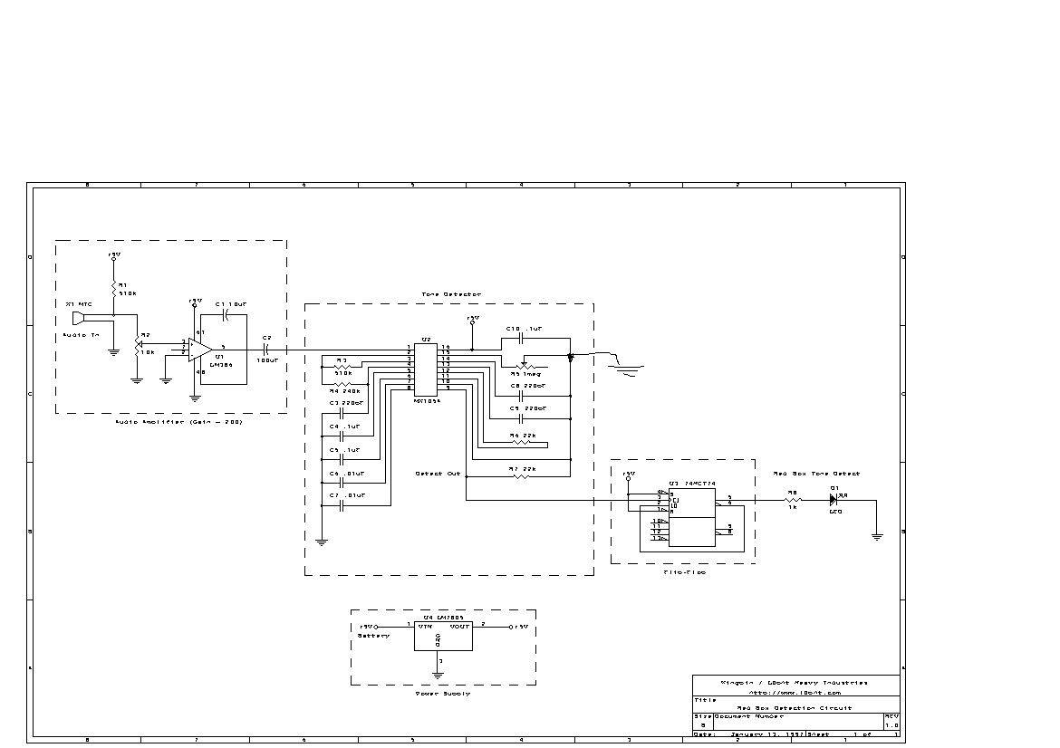
BUG FIX: A ground connection is missing from the schematic, and proper detection will not work without it. On the right side of U2 (MX105A), components C8, C9, C10, R5, R6, R7 are all connected together. This connection needs to be pulled to ground.