Excerpt from the ARRL Antenna Book
... A second improvement technique is the use of circularly polarized repeater antennas. This technique has been used in the FM broadcast field for many years, and has been considered for use in the mobile telephone service as well. Some experiments by amateurs have proved very promising, as discussed by Pasternak and Morris1.
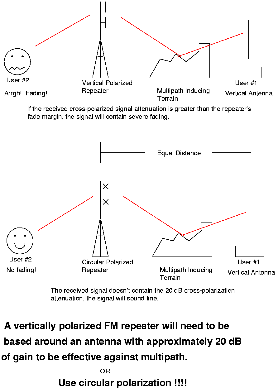
The improvement afforded by circular polarization is primarily a reduction in mobile flutter. The flutter on a mobile signal is cased by reflections from large buildings (in urban settings) or other terrain features. These reflections cause measureable polarization shifts, sometimes to the point where a vertically polarized signal at the transmitting site may appear to be primarily horizontally polarized after reflection.
A similar situation results from multipath propagation, where one or more reflected signals combine with the direct signal at the repeater, having varying effects on the signal. The multipath signal is subjected to large amplitude and phase variations at a relatively rapid rate.
In both described situations described here, circular polarization can offer considerable improvement. This is because circularly polarized antennas respond equally to all linearly polarized signals, regardless of the phase of polarization. At this writing, there are no known sources of commercial circularly polarized omnidirectional antennas for the amateur bands. Pasternak and Morris describe a circularly polarized antenna made by modifying two commercial [FM broadcast] four-pole arrays.
Excerpt from the text EW101
... An important EW polarization trick is to use a circularly polarized antenna to receive a linearly polarized signal of unknown orientation. You always lose 3 dB but avoid the 25 dB loss that would occur if you where cross polarized.
As you can see, circularly polarized antennas can offer a significant improvement in a repeater's overall performance. It should be noted though, that you'll need a minimum of two antenna bays, spaced one wavelength apart, to reach unity gain (0 dB). A single bay would have a -3 dB gain in each polarization.
Practical Example
The following is an example using the N9DKH 147.075 MHz repeater system in Green Bay, WI
Givens for the current repeater system:
- TX output power : 45.7 dBm (38 watts)
- Duplexer system losses : 6 dB
- 80 feet RG-213 feedline loss : 2.17 dB
- Antenna gain2 : 3 dB (2-bay dipole, vertical polarized)
Total effective radiated power (ERP) is 40.53 dBm (11.3 watts), effective receive gain is 0.83 dB. And fading!
Givens for experimental system:
- TX output power : 45.7 dBm (38 watts)
- Duplexer system losses : 6 dB
- 80 feet 7/8" Heliax : 0.43 dB (optional Superflex jumper losses not included, 0.2 dB)
- Antenna gain : 0 dB (2-bay circular polarized)
Total effective radiated power (ERP) is 39.27 dBm (8.5 watts), effective receive gain is -0.43 dB. No fading!
Givens for the alternate system:
- TX output power : 45.7 dBm (38 watts)
- Duplexer system losses : 6 dB
- 80 feet 7/8" Heliax : 0.43 dB (optional Superflex jumper losses not included, 0.2 dB)
- Antenna gain2 : 3 dB (2-bay dipole, vertical polarized)
Total effective radiated power (ERP) is 42.27 dBm (16.9 watts), effective receive gain is 2.57 dB. And fading!
As you can see, this system is within 1.6 dB of the current repeater system, with the receive side being attenuated by 0.43 dB which is about equal to the loss caused by a PolyPhaser, if there was one.
The alternate system has a 3 dB improvement in transmitted ERP and a 2.57 dB advantage in received signals. This is barely enough to overcome your typical fade situation, which is commonly 10 dB or more, and that commercial antenna set you back $500!!
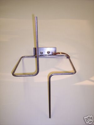
A Picture
- Overview of a practical example Math and science will always prevail over the ego.
Links
- Homebrew Circularly Polarized Antennas by Mark Weiss
- High Gain J-pole by Mark Weiss
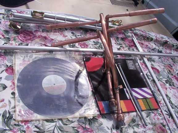
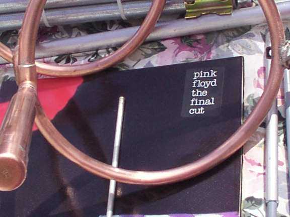
- Homebrew Circularly Polarized Antenna Picture 1 (constructor unknown)
- Homebrew Circularly Polarized Antenna Picture 2
- Homebrew Circularly Polarized Antenna Picture 3
- Homebrew Circularly Polarized Antenna Picture 4
- WA7X Beacon The Cycloid Dipole
- "Bucket" Lindenblad 440 MHz antenna using a 5 gallon bucket and copper foil tape
- Another Homebrew Circularly Polarized Antenna Picture 1
- Another Homebrew Circularly Polarized Antenna Picture 2
Notes
Polarization Mismatch Loss (dB) = 20 * log10(cos D) Where D is the misalignment angle between the two antennas.
Polarization Mismatch Between Two Linearly Polarized Waves as a Function of Angular Orientation
Orientation Angle          Polarization Mismatch (dB)

0.0 (aligned)              0.0
15.0                       0.3
30.0                       1.3
45.0                       3.0
60.0                       6.0
75.0                       12.0
90.0 (orthogonal)          infinite (real world varies 20-35 dB)
The following is from CushCraft
One common misconception in the communication industry is that there is always a 3 dB polarization mismatch between linearly and circularly polarized antennas. This will only be true if one antenna is purely circularly polarized and the other is purely linearly polarized. In most cases, it is unlikely that the circularly polarized antenna will have an axial ratio of 0 dB and field components exactly 90 degrees out of phase. Similarly, it is possible that the linearly polarized antenna may have another minor field component.
Polarization Mismatch Between a Linearly and Circularly Polarized Wave as a Function of the Circularly Polarized Wave's Axial Ratio
Axial Ratio             Minimum Polarization Loss (dB)      Maximum Polarization Loss (dB)

0.00                    3.01                                3.01
0.25                    2.89                                3.14
0.50                    2.77                                3.27
0.75                    2.65                                3.40
1.00                    2.54                                3.54
1.50                    2.33                                3.83
2.00                    2.12                                4.12
3.00                    1.77                                4.77
4.00                    1.46                                5.46
5.00                    1.19                                6.19
10.00                   0.41                                10.41
Minimum polarization loss occurs when the strongest linear field component of the circularly polarized wave is identically aligned with the linearly polarized wave.
Maximum polarization loss occurs when the weakest linear field component of the circularly polarized wave is aligned with the linearly polarized wave.
1 W. Pasternak an M. Morris, The Practical Handbook of Amateur Radio FM & Repeaters (Blue Ridge Summit, PA: Tab Books Inc, 1980), pp 355-363.
2 Real world antenna gain (not advertising lies) for closely spaced co-linear dipole element can be estimated via: Gain (dBd) = 10 * log10(number of radiating elements) + (gain of individual element). Example, 4-bay open dipole array has 6 dBd of gain.