This is an archive of an article that lives here.

DWL-650 Antenna


The DWL-650
I purchased this card because it was the cheapest (<$100 @ CompUSA). I knew that I was going to build an antenna, but wanted to do so very cheaply. The connectors for the Lucent cards are costly and hard to find. There were some nice pictures at seattlewireless that convinced me it would be easy to add an antenna.

I also ran into some interesting drivers for this card. More on that later.


The Specs
From the pictures it really looked like there was supposed to be a jack at the end of the antenna PCB. I wanted to find out how to add one. I was hoping to find a good example of how someone did this in a real production on the FCC pages. First I looked for new entries in the FCC ID database under D-Link's name. When that failed, I searched for all items between 2300 and 2500 mhz created in the last year (use the advanced search). This had excellent results. The D-Link card uses the Intersil Prism II chipset, and information on the Intersil page specified a list of manufacturers that make products with the intersil chipset. I just checked all FCC pages of companies that matched. Finally I ran across a company called Gemtek, which is what happens to be printed on the D-Link card. Obviously I should have looked there first. So the D-Link DWL-650 = Gemtek WL-211F.
While Gemtek requested that the FCC not post the schematics for the WL-211F, they did post schematics for a nearly identical USB card also based on the Intersil parts. These USB card schematics reveal how to connect an antenna.
Using the FCC documents would probably be helpful if you were looking for information about other chipsets as well.

So here are the docs: (I have copies should the FCC take these offline)

The DWL-650/WL-211F, less schematics:
http://gullfoss2.fcc.gov/cgi-bin/ws.exe/prod/oet/forms/reports/Search_Form.hts?mode=Edit&form=Exhibits&application_id=97155&fcc_id=MXF-WL211F

Similar Access Point made by Gemtek:
http://gullfoss2.fcc.gov/cgi-bin/ws.exe/prod/oet/forms/reports/Search_Form.hts?mode=Edit&form=Exhibits&application_id=99061&fcc_id=MXF-WL280

Notice how similar the two pcb's are:


Add the jack
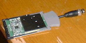
As you can see from the picture of the USB board, they just left one antenna lead empty. The other is connected straight to a small swivel antenna. We will do basically the same thing - leave one PCB anteanna in tact, and replace the other with an external jack. You could probably disconnect both PCB antennas and just use the external antenna, but I wanted to maintain one for everyday use around the house.
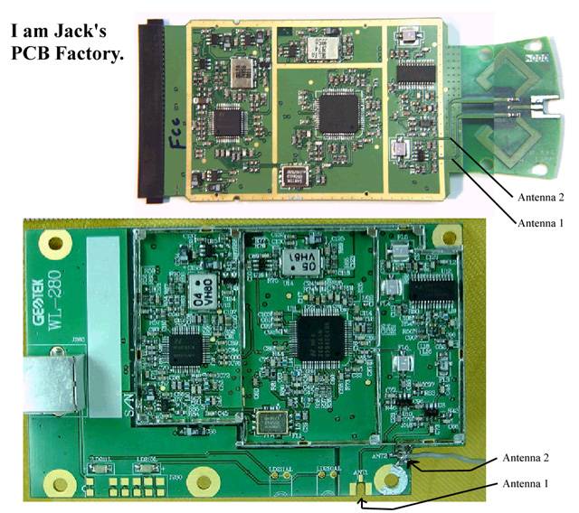
Also, I connected the external antenna to each of the onboard leads, and neither seemed to give any better performance than the other, so I suspect that it doesn't matter which one you use.


1. remove the small capacitor
2. connect antenna lead to ANT3 lead

next...


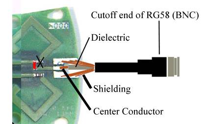
I used an old piece of thinnet (10base2) wire because it is easy to find and no one wants it. Plus it's 50 ohms, which we need. And best of all, it has a free connector on the end. I so cannot afford $10 connectors from digikey. 
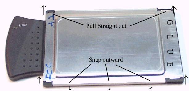
Just solder it right on the card. You'll need to trim the gray plastic case that snaps together to allow it to fit through. Don't trim too much, a little pressure from the enclosure should provide some minor strain relief.

That should do it. You can use another peice of RG58 with BNC connectors to hook up to your antenna. If you put a BNC jack on the antenna, you only need to get one adapter, a pass thru.


A note on opening PCMCIA cards
It's kind of a pain. The metal case is glued to the black plastic connector. There are snaps along the side that you need to pry. There are inserts with catches into the housing that you need to pop out.
Use thin tools and very little force.


Where it says "snap outward", you really only need to pry outward a little bit, then push the small innter tab in the other direction to free it.

Other things about this hardware
The pertinent schematics are on sheet 5 of the USB board stuff here. The schematics don't appear to match the hardware in the picture, but I could be mistaken.

This is a 50 ohm system according to the Intersil docs.

It would be nice to better match a given antenna to this card. Any ideas how?

Any other suggestions or comments would be awesome. email me.


Intersil Prism II Linux Drivers
There are two working drivers for this card. The Linux-wlan drivers and the pcmcia-cs drivers. The pcmcia-cs driver code looks a little ratty, but is really cool because it uses the Linux wireless extentions (why didn't wlan use them?????). With pcmcia-cs you can easily monitor link status and levels in /proc/net/wireless. You can easily configure the card with iwconfig. Its the same stuff the Lucent people get to use.

On the other hand, the wlan drivers have ugly config files instead of iwconfig. There are no tools yet to check the card link status and such that I know of yet (for wlan-ng, that is). They didn't use the wireless extensions (a very nice set of ioctl's and api in include/linux/wireless.h). You also need the pcmcia-cs package just to compile the wvlan driver.

At any rate...
Linux-wlan
pcmcia-cs


Links