The local loop consists of feeder cables which are used to carry telephone traffic from the phone company's central office, which is also called a wire center, to various service areas established throughout the geographic territory served by that particular central office.
In most cases, local loops are copper (conventional twisted pair). Inside the central office, the local loop begins at the Main Distribution Frame (MDF). The MDF is a very large structure where the copper wires which make up a local loop are attached. Hundreds of these wires are bundled together into a single cable bundle several inches thick. This cable runs through the basement of the central office and out into the phone company's conduit system and then into a neighborhood. At some point, the cable will come out of the conduit system into an above-ground cabinet. In this cabinet, each of the individual wires will be attached to a particular location on a small panel. These individual wires are "cross-connected" at this point with wires running into nearby homes and businesses. There were over 24,000 above-ground cabinets and 240 below-ground Controlled Environmental Vaults (CEV) in Illinois Bell territory.
There are also other types of local loops.
Sometime the feeder cables are equipped to act as Subscriber Loop Carrier (SLC) systems. In the case of copper cables, this is accomplished by installing subscriber digital loop carrier systems. Alternatively, fiber optic cables can be used to transmit the digital signals optically. The actual equipment used at the end of the feeder to provide the loop carrier system functionality is typically housed in special above-ground cabinets or in below-ground CEVs. The area served by digital carrier feeder cable is classified as a carrier serving area.
Only about 5% of phone company's loops are subscriber digital loop carriers. The other 95% is still plain old copper. However, much of today's growth is being implemented through the placement of subscriber loop carrier systems.
Select a picture for larger image.
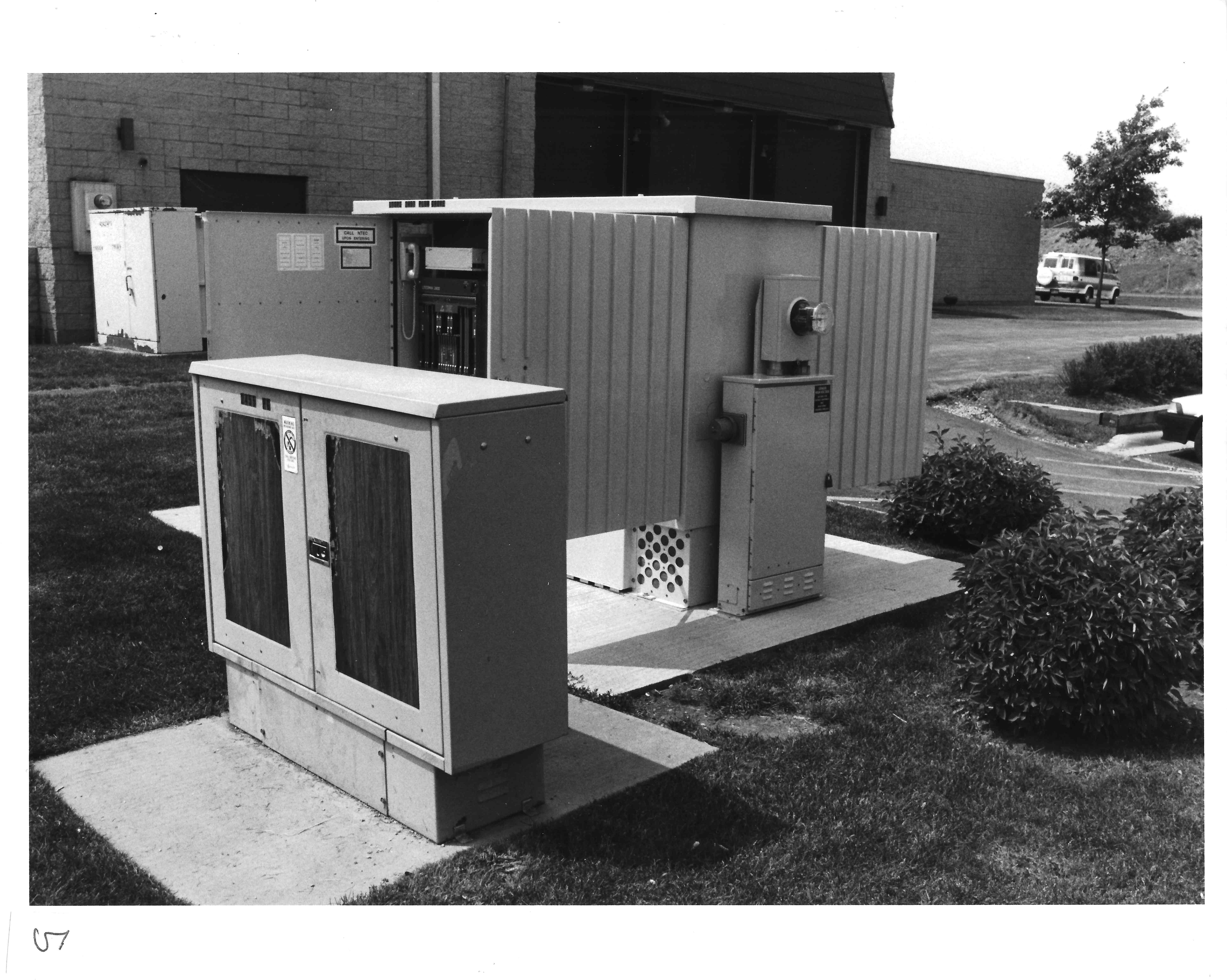
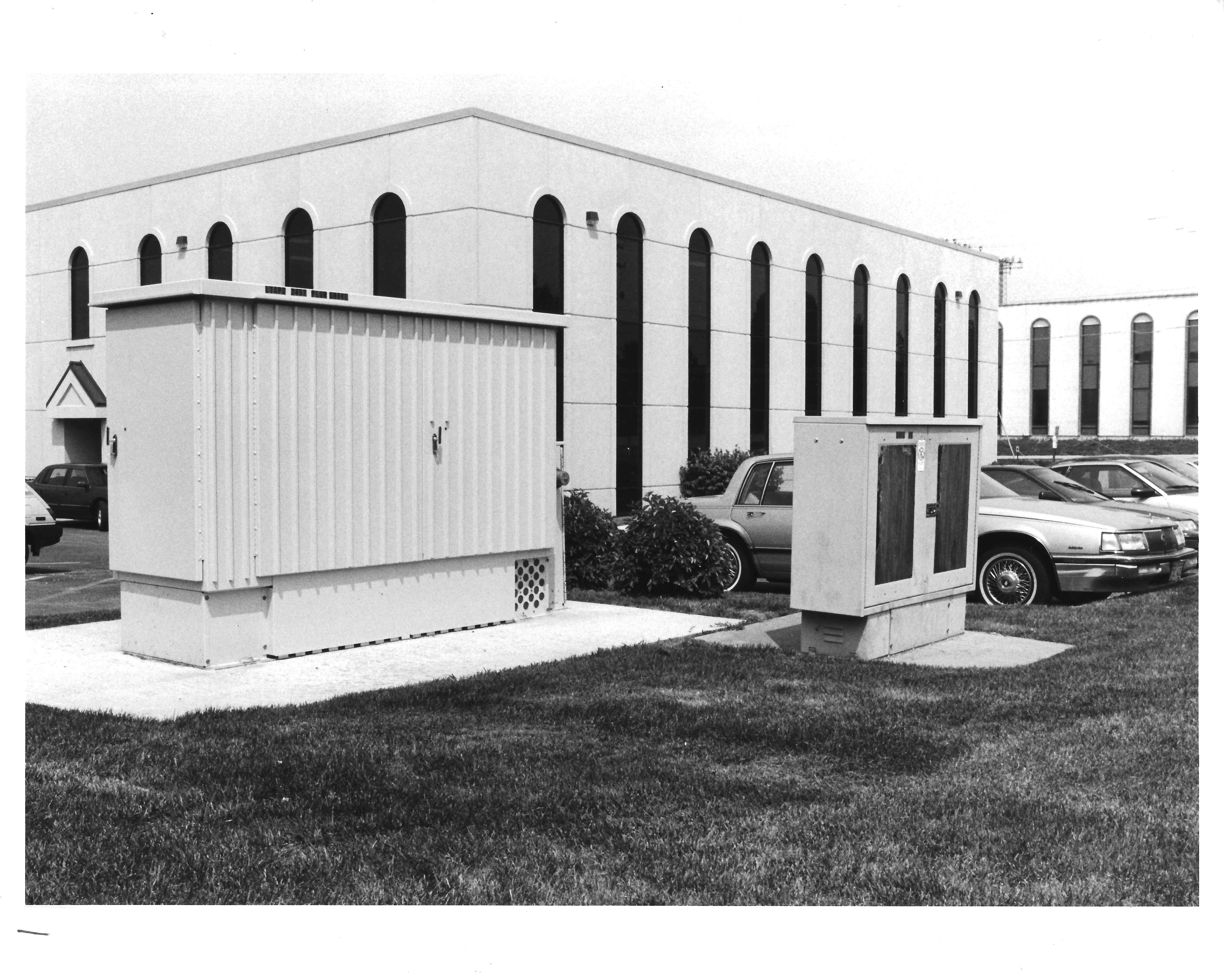 Above-ground cabinet.
This is an external view of a DSC Litespan 2000, model 2020. The smaller cabinet is a conventional cross-connect box and is described later. This cabinet is approximately 3 feet wide, 9 feet long and a little over 6 feet high. It rests on a 10 by 14 foot concrete pad. Prior to pouring the pads, four cable conduits were installed for telephone cable at one end and additional conduits for commercial power were installed at the other end. This particular cabinet is designed to work with fiber optic transmission cables. At maximum capacity, this cabinet is capable of serving 2016 lines. The base is designed to hold up to 40 12-volt batteries to maintain service in case of commercial power failure. These batteries can be recharged using a portable generator if the commercial outage is extensive.
 Inside the cabinet.
This shows the telephone cables entering the splice chamber. The small plastic devices attached to the individual wires are splices which connect the individual loops to the cabinet's internal electrical equipment. Before each line enters the electronic package it passes through protection equipment which safeguards the line from lightning surges and other over voltage situations. Both sides of the cabinet open up to provide access to the loop electronics and protections circuitry.
 Protection circuits.
Surge and over voltage protection circuitry is shown in this photo. The protection circuitry also provides test access and circuit isolation functions.
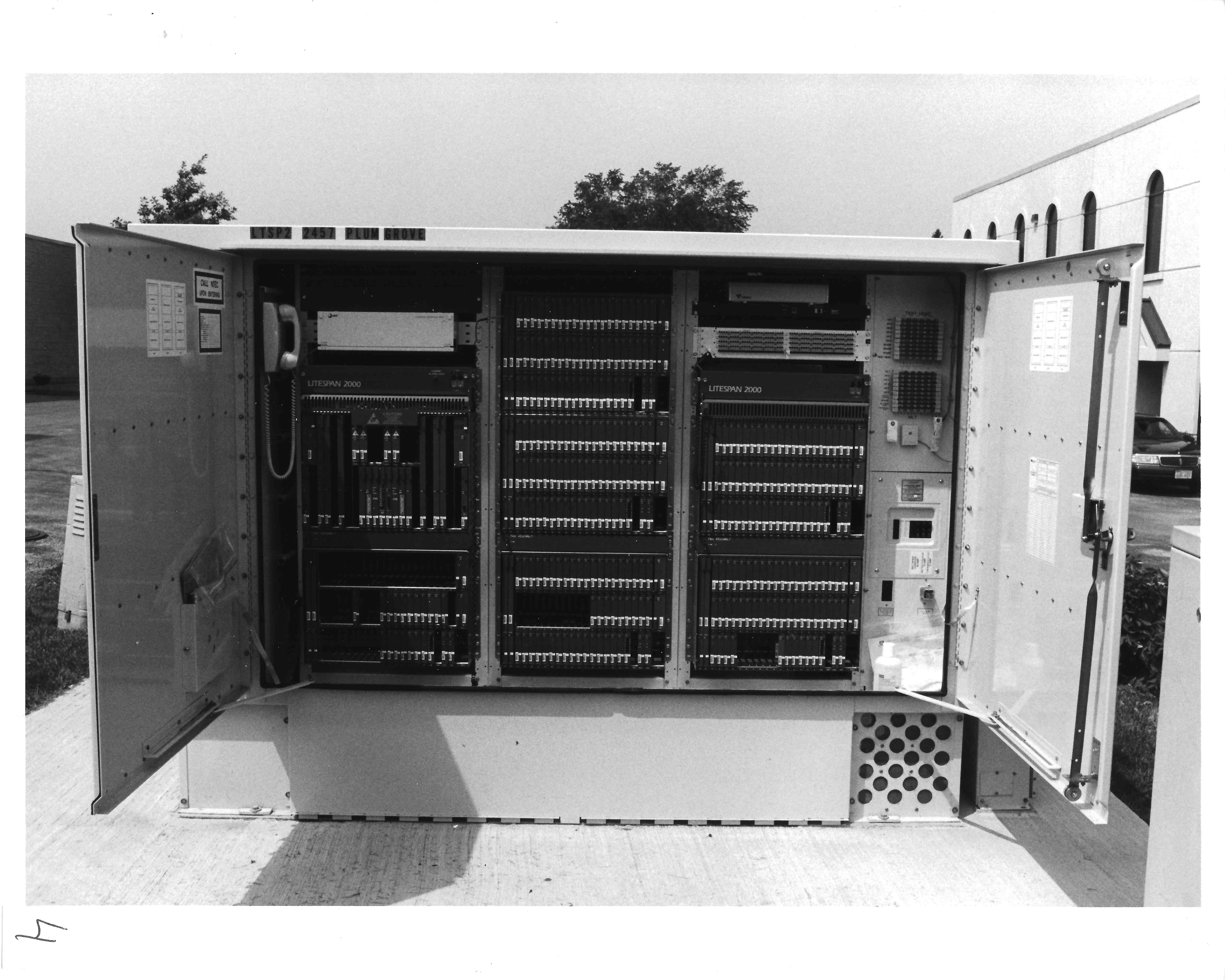 Loop electronics.
Back of the cabinet with the doors open. This shows the actual Litespan 2000 circuit cards.
 Front of cabinet.
This shows the front side of the cabinet housing the commercial power interface and circuitry for converting AC power to the DC power used by the equipment and required to keep the batteries in a charged state. In addition, a telemetering system monitors power systems, access conditions, security, temperature and other vital functions and relays any abnormal conditions back to a monitoring center.
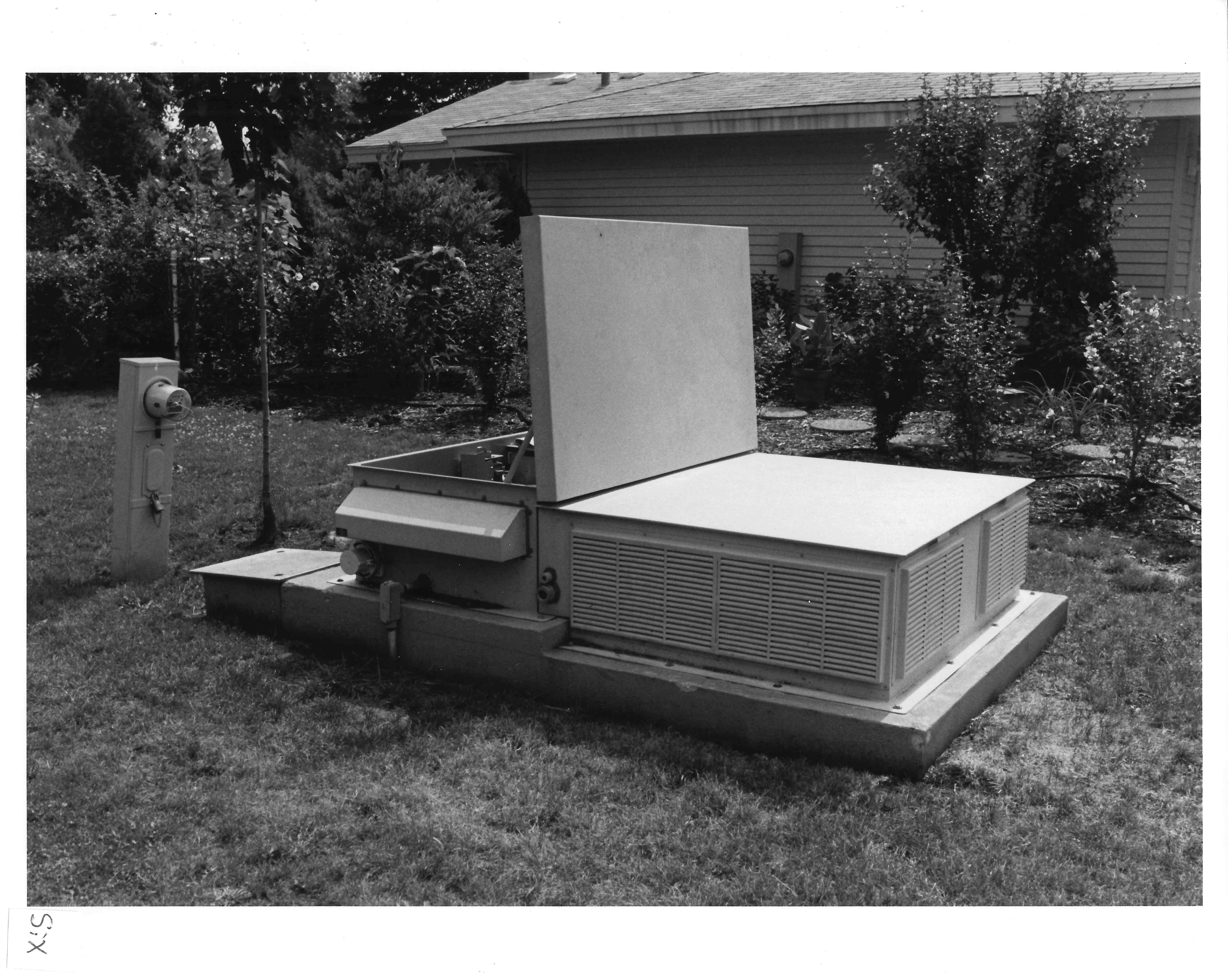 Controlled environmental vault.
This shows the access hatch to a controlled environmental vault. CEVs are concrete enclosures buried below the ground. There are two sizes of CEVs, the smaller one has outside dimensions of 16 feet in length, 6 feet in width and 9 feet in height. A larger version is 24 feet in length with the same height and width dimensions. A 16 foot CEV can be used to serve up to 3,456 lines. The maximum capacity of the 24 foot CEV is 5,760 lines. CEVs are preassembled and shipped to the construction site. Telecommunication equipment is installed at the factory prior to shipment. The top and bottom sections are build separately and they are joined at the site. A crane with a 100 ton lifting capacity is required to lower the preassembled sections into the excavation.
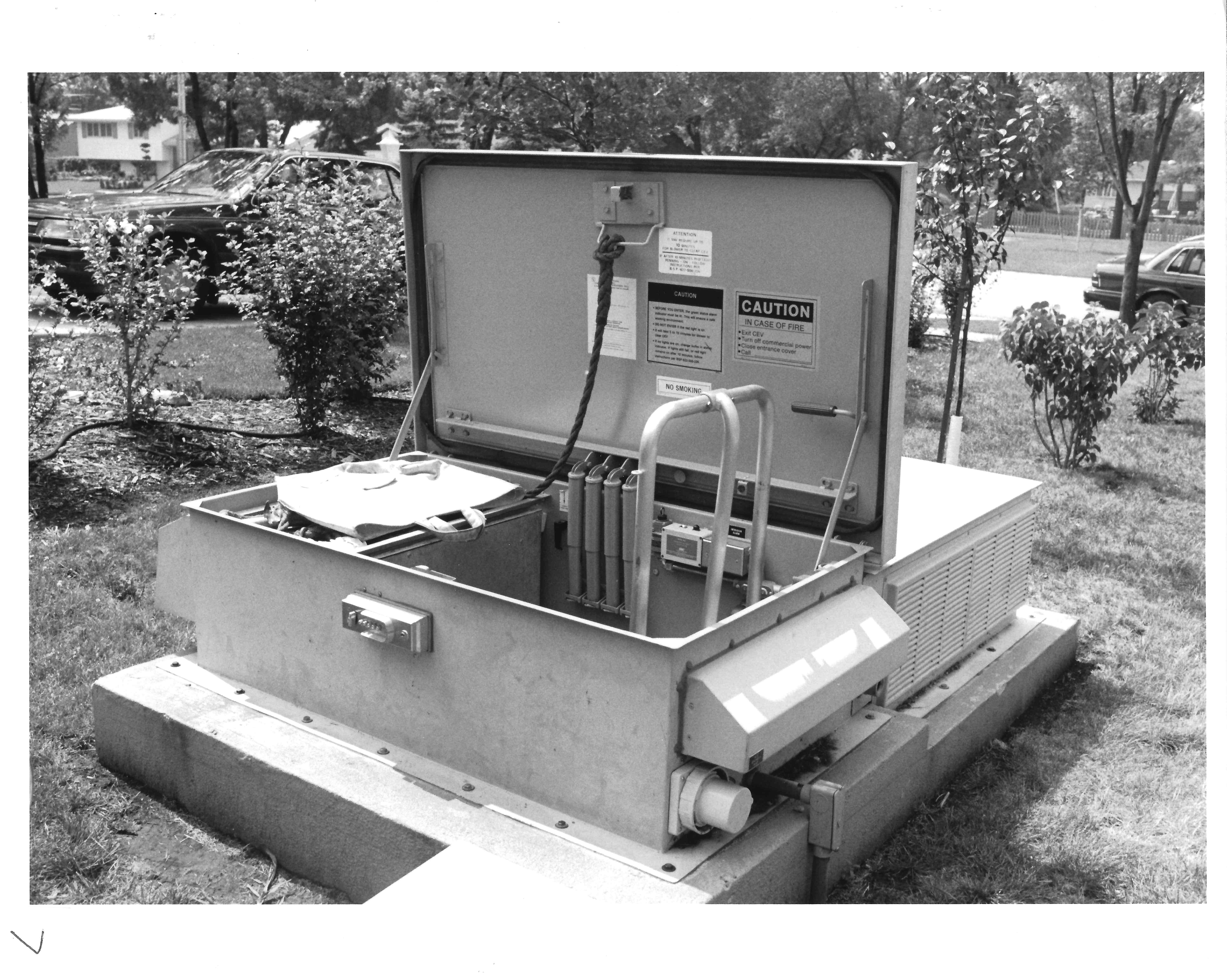 CEV hatch open.
A coded door lock (Simplex) secures the hatch. Opening the access hatch activates an intrusion alarm which results in the monitoring center being notified via telemetering equipment that the hatch has been opened. A view of the status lights indicating when it is safe to descend and the ladder leading down to the interior of the CEV are shown in the picture. Employees must check these indicators before entering. Upon entering the vault, employees must call the monitoring center and provide appropriate identification and indicate the purpose of their entry.
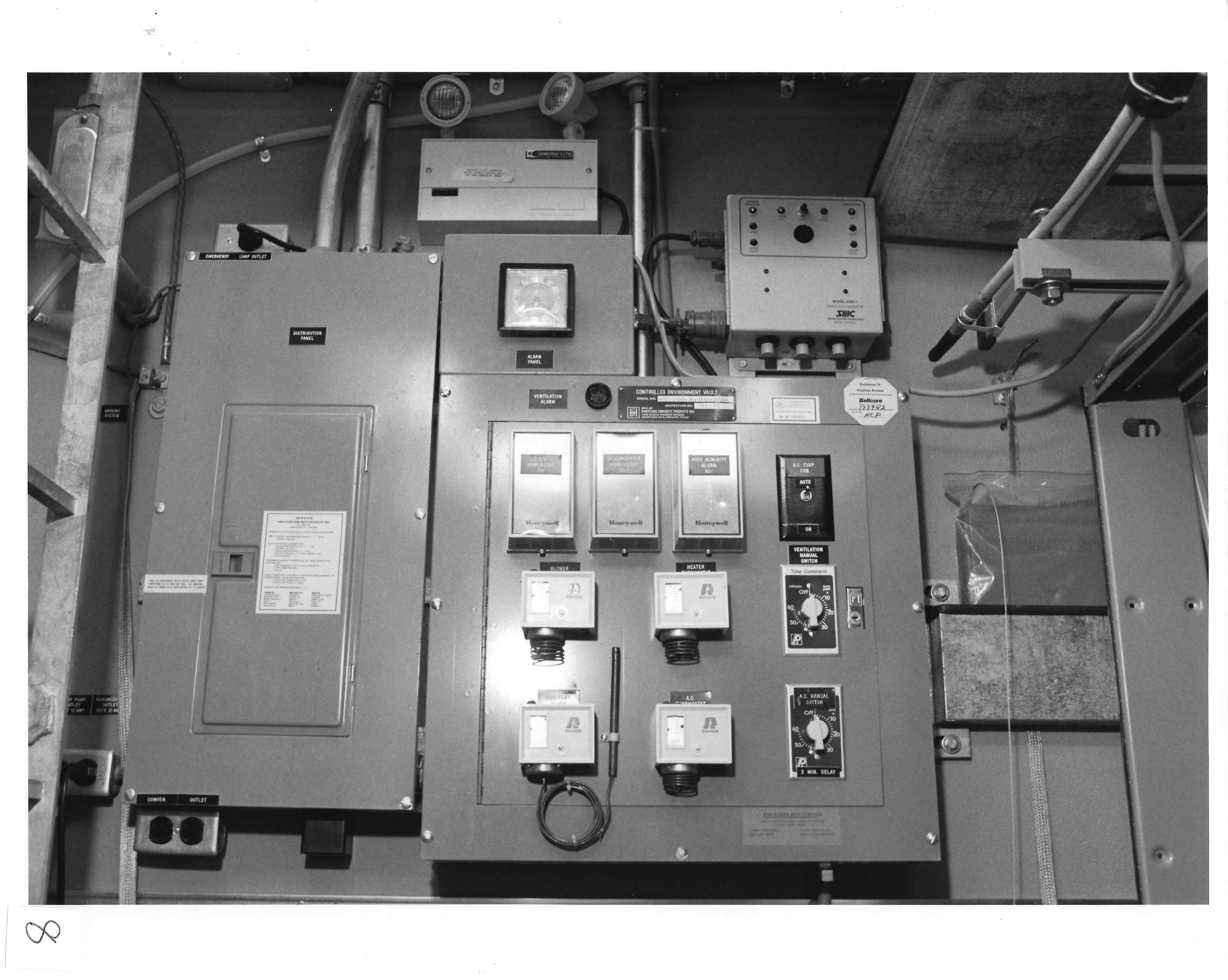 CEV alarm panel.
This alarm panel detects smoke, explosive or toxic gases as well as monitoring temperature, humidity, ventilation, water level and power systems.
 Cables entering the vault.
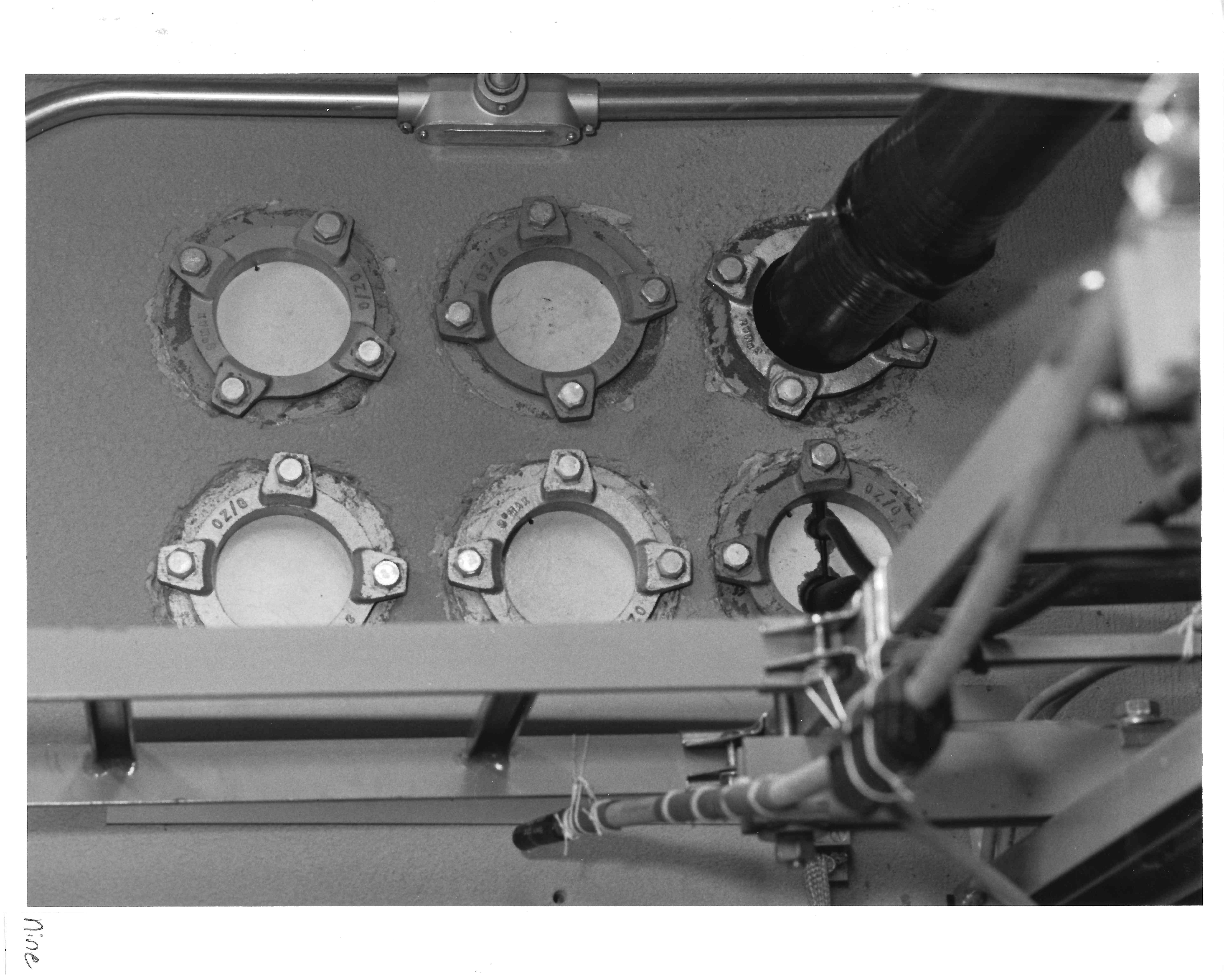
Telecommunications cables enter and leave the vault through conduit placed high on the back wall. This picture shows the six conduits installed in this vault. The vault is relatively new so only two are in use. Even if the vault was fully loaded, there would be at least one space conduit reserved for emergency use. The large black cable emerging from the top right-hand corner is copper wire local distribution cable connecting to homes, businesses, schools and other locations in the neighborhood. The smaller black cable emerging from the lower right-hand conduit contains the fiber optic cable. All the conversations carried on the individual wires contained in the large black cable can be converted to pulses of light and transmitted to the central office over the fiber optic cable.
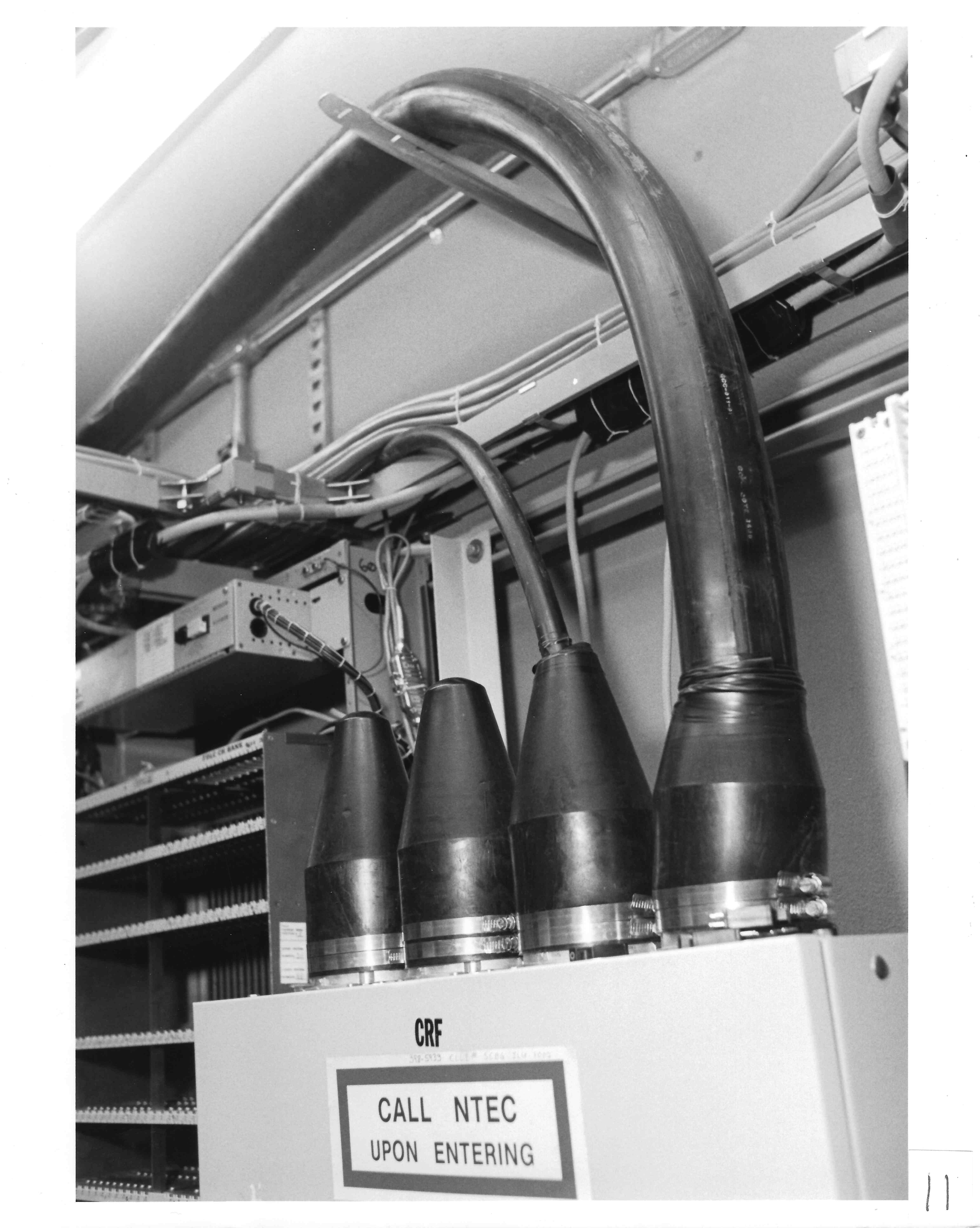
 Splice chamber.
This shows the cable entering the splice chamber. The cover of the splice chamber has been removed for these pictures. This splice chamber is used to connect the copper cables coming into the vault to other equipment located inside the vault.
 Top of splice chamber.
This is the top of the splice chamber. Note that although there are six conduit entrances into the vault there are only four black rubber "boots" on top of the splice chamber. This reflects the fact that conduits are held in reserve for emergency cable pulls in case of a fiber cut and is not expected to used are part of the standard circuit configuration.
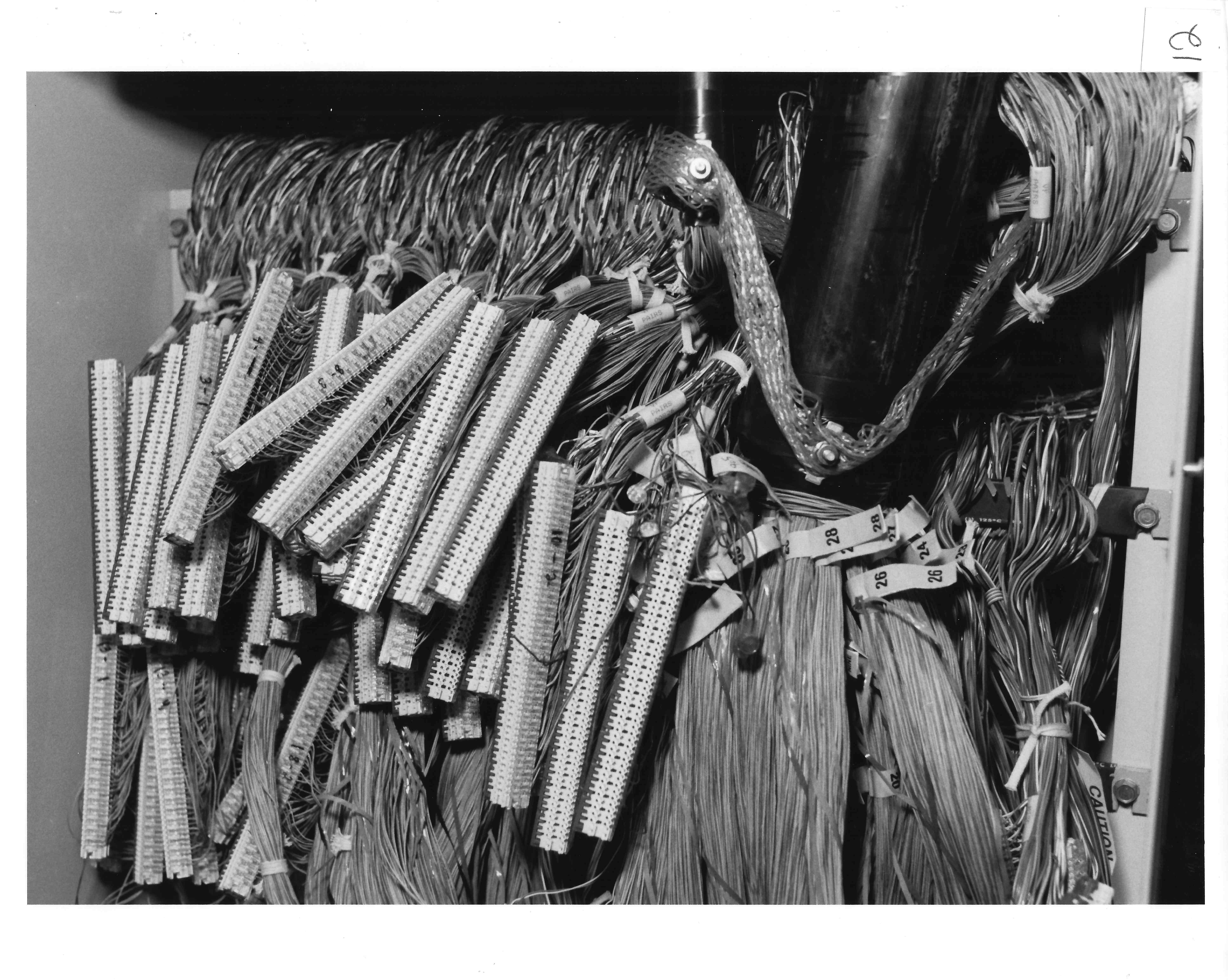 Closeup inside splice chamber.
This is a closer view of the actual spliced connections. Each splice connects 50 pairs together.
 Protection equipment.
The above splices connect the copper wire pairs to protection equipment located next to the splice chamber. This equipment provides the identical function performed by the same equipment in the above-ground cabinet. It serves to safeguard the vault and personnel working on the equipment from lightning surges and other over voltage situations.
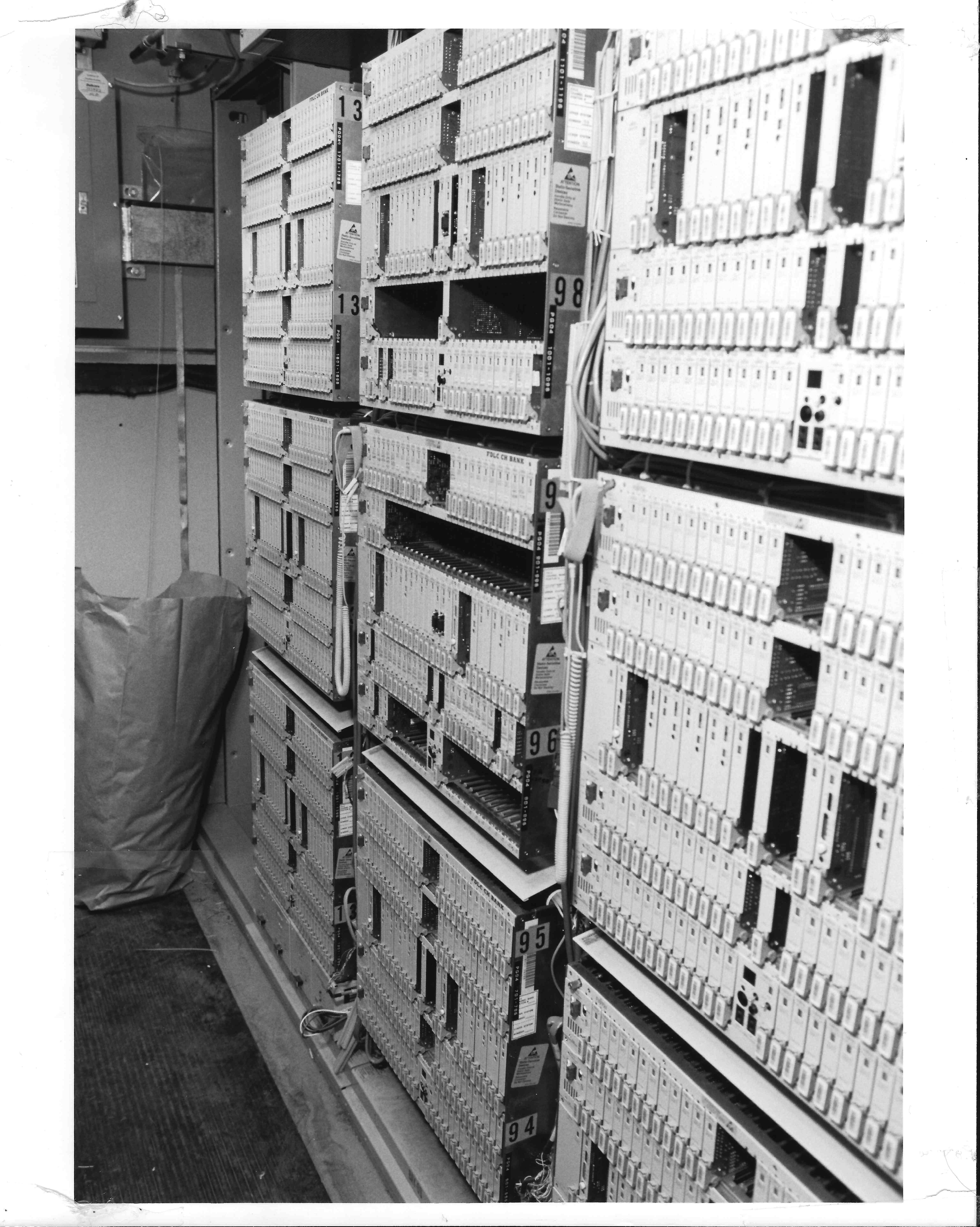 SLC (Subscriber Loop Carrier).
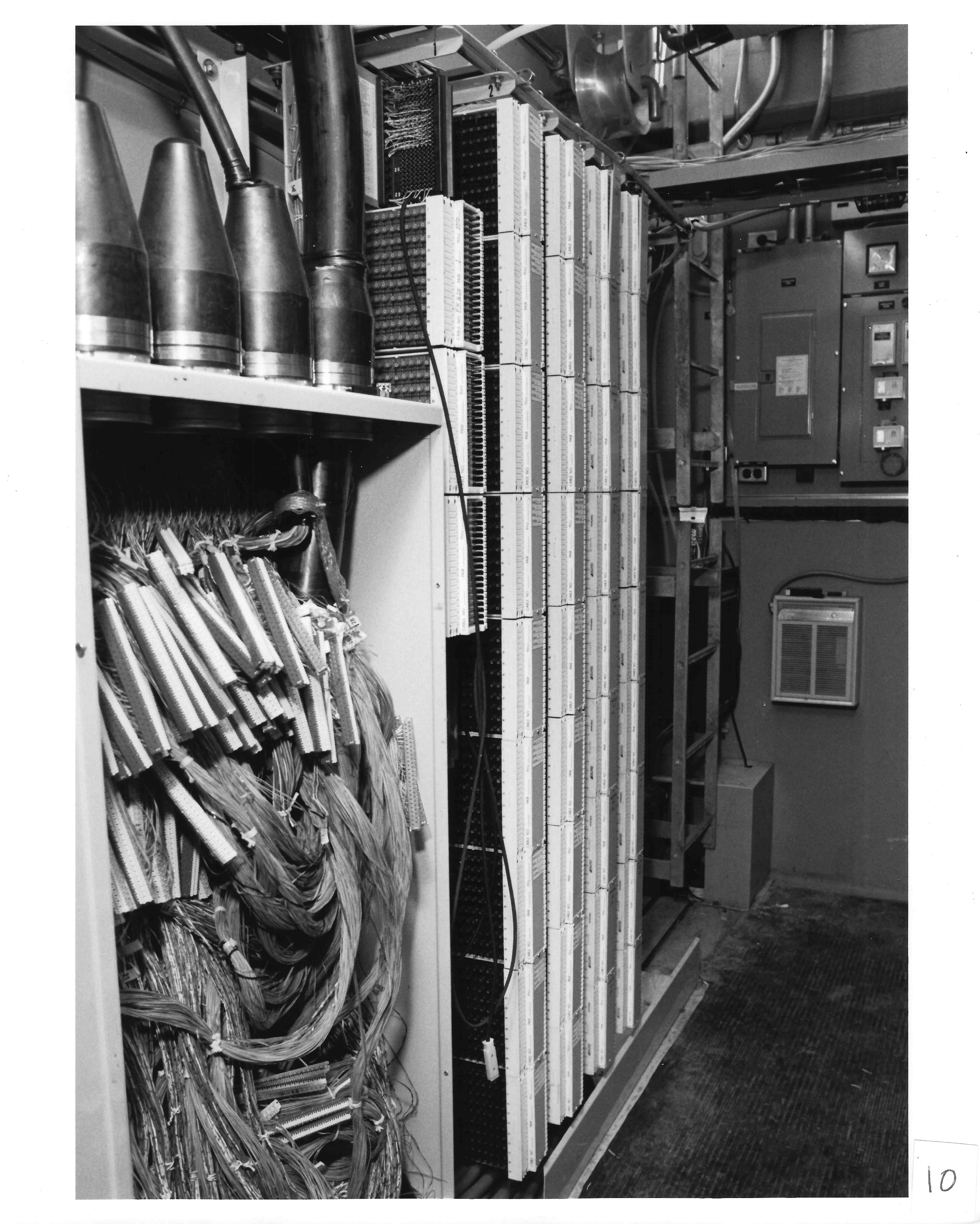
The telephone lines from homes and businesses in the area are eventually connected to this electronic equipment, a subscriber loop carrier system. This equipment converts digital signals coming from the central office into analog signals for delivery to the home. In the other direction, the equipment converts the analog signals to digital signals and combines digital signals from many calls into high speed pulses of light which are sent over fiber optic cables back to the central office.
The Lucent SLC Series 5 is a very popular carrier system.
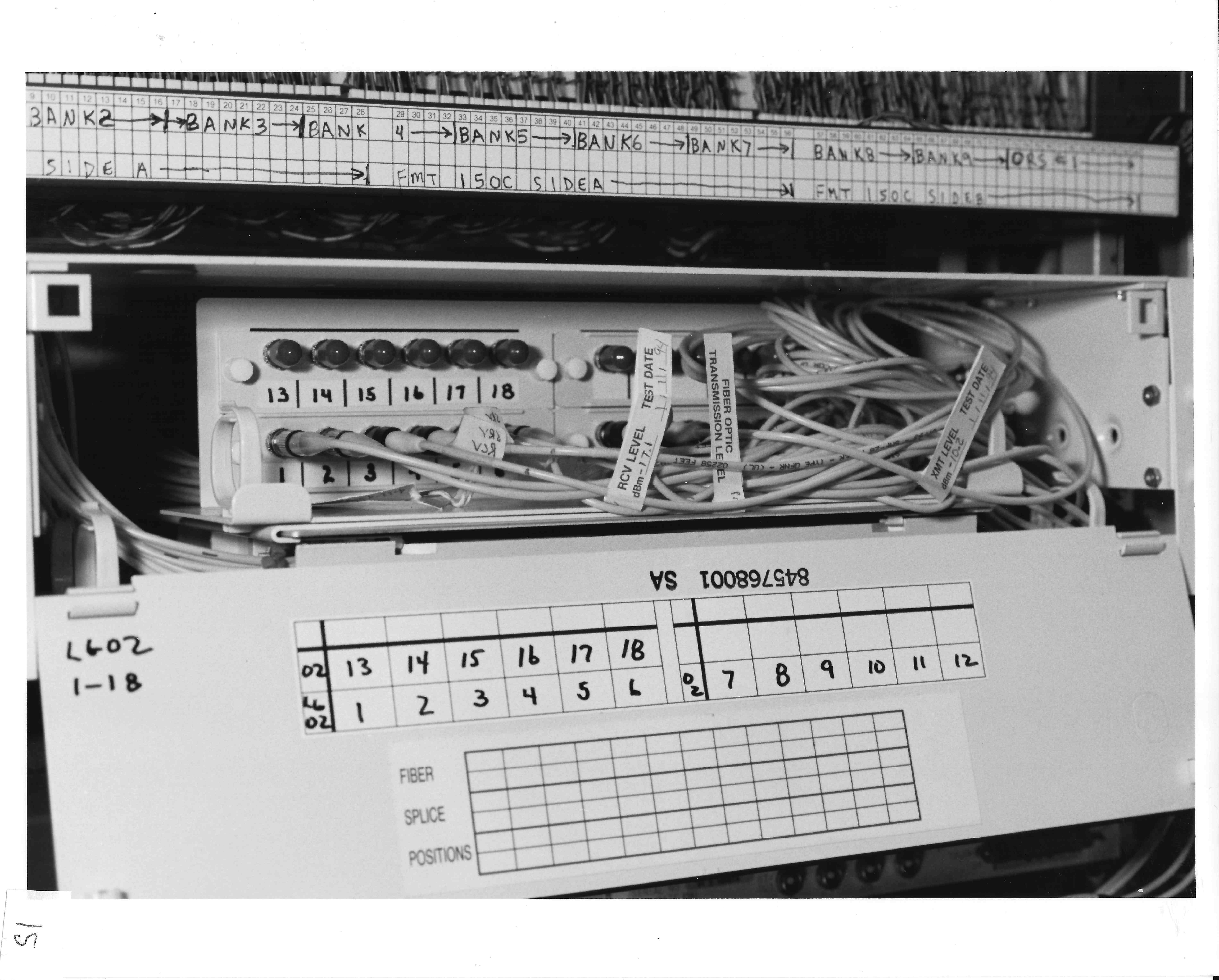 Fiber cross-connect.
This shows the fiber optic cross-connect panel. Individual fibers are cross-connected to the appropriate equipment which converts the light pulses to electrical pulses used by the digital loop carrier systems. A Nortel FMT-150C in this case.
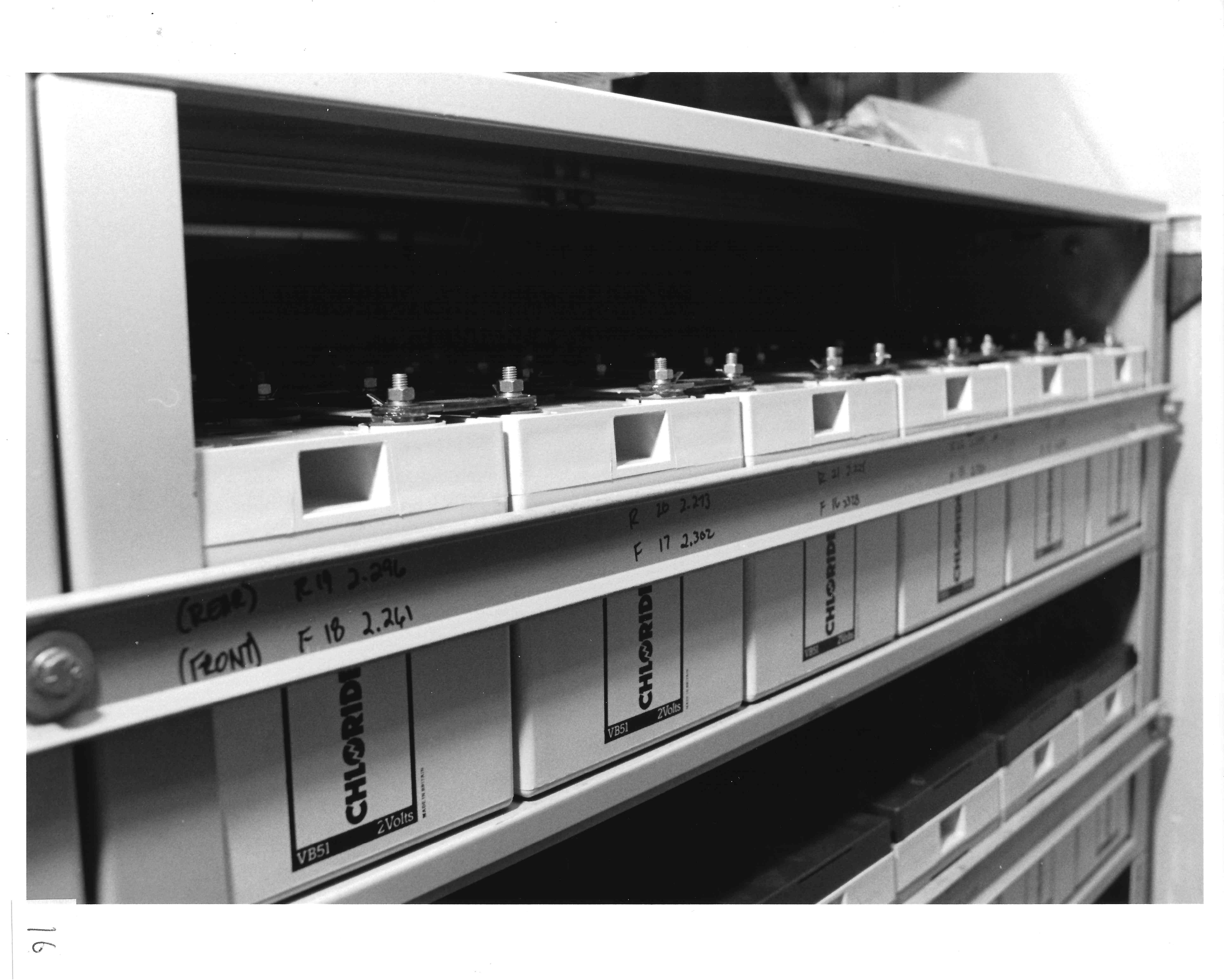 Batteries.
To maintain service in case of commercial power interruption, the CEV also contains banks of batteries to provide stand-by power. If an extended power outage occurs, connections are provided to permit an external generator to be connected to the battery charging equipment.
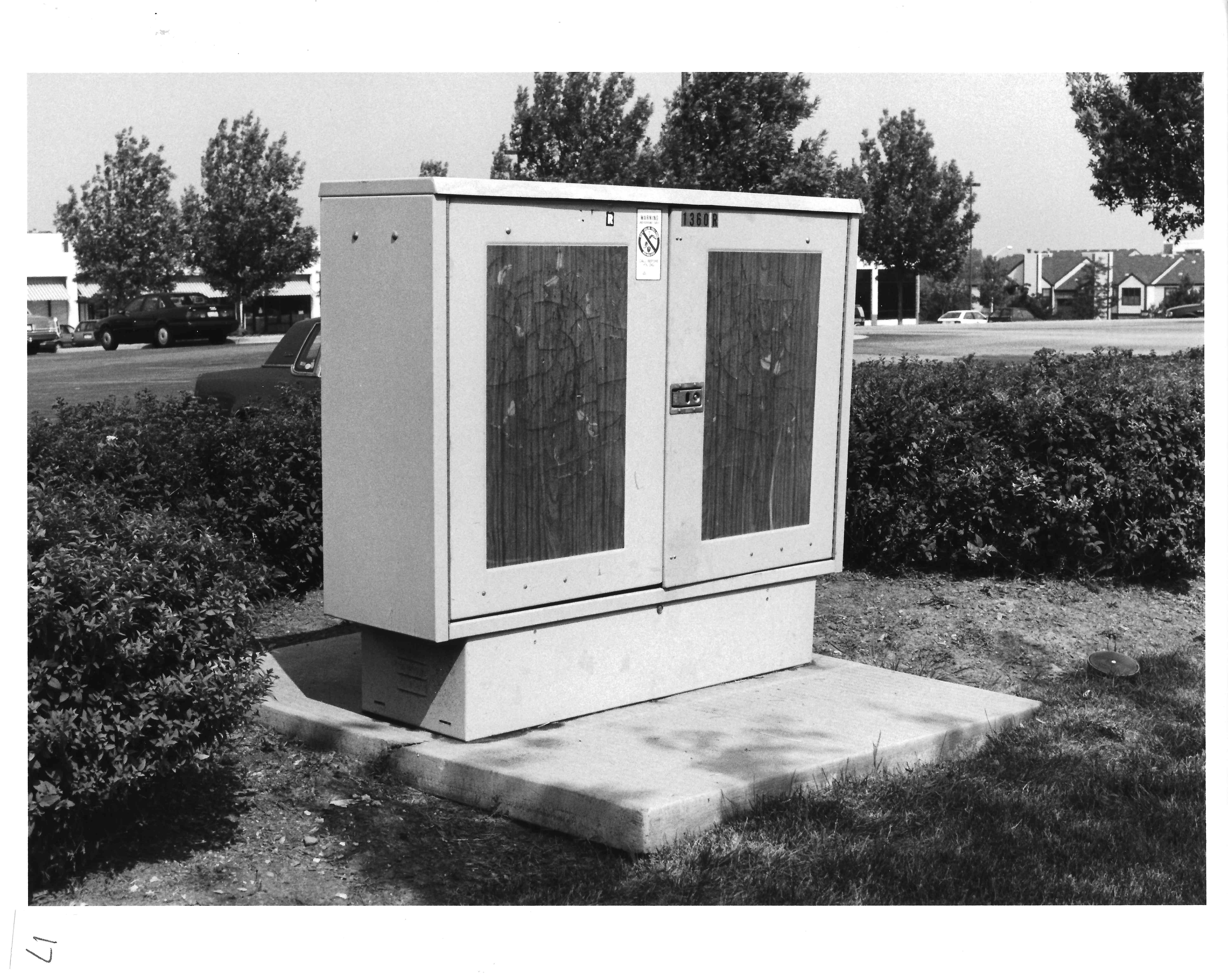 Cross-connect box.
This is a cross-connect box. It is used to cross-connect feeder cables to local distribution cables serving the immediate area. The box's physical dimensions are 17 inches wide, 5 feet long and 4 feet high. Doors on both sides of the cabinet swing open to provide the technicians access. The box is engineered to economically connect the pairs serving the immediate area to the feeder cables coming from the central office or in some cases from a CEV or remote terminal.
Depending on the nature of the area being served, local distribution pairs will exceed feeder pairs by some predetermined ratio. For instance, if the ratio is 1.5:1, then there would be three local distribution pairs for each two feeder pairs. When installing cable within a given community, it is not possible to predict, on a lot-by-lot basis, which customers will be ordering two or more lines. However, based on demographics of a given area, the phone company can estimate the total demand for service. As customers order service the phone company can cross-connect a feeder cable pair coming from the central office to and appropriate local distribution pair serving the end user customer. This system also allows them to more rapidly restore service by switching a customer service from a defective pair to one that is in working condition. Each cross-connect box is designed for a particular type of connector and for the cable feeder to local distribution cable ratio most appropriate for that area.
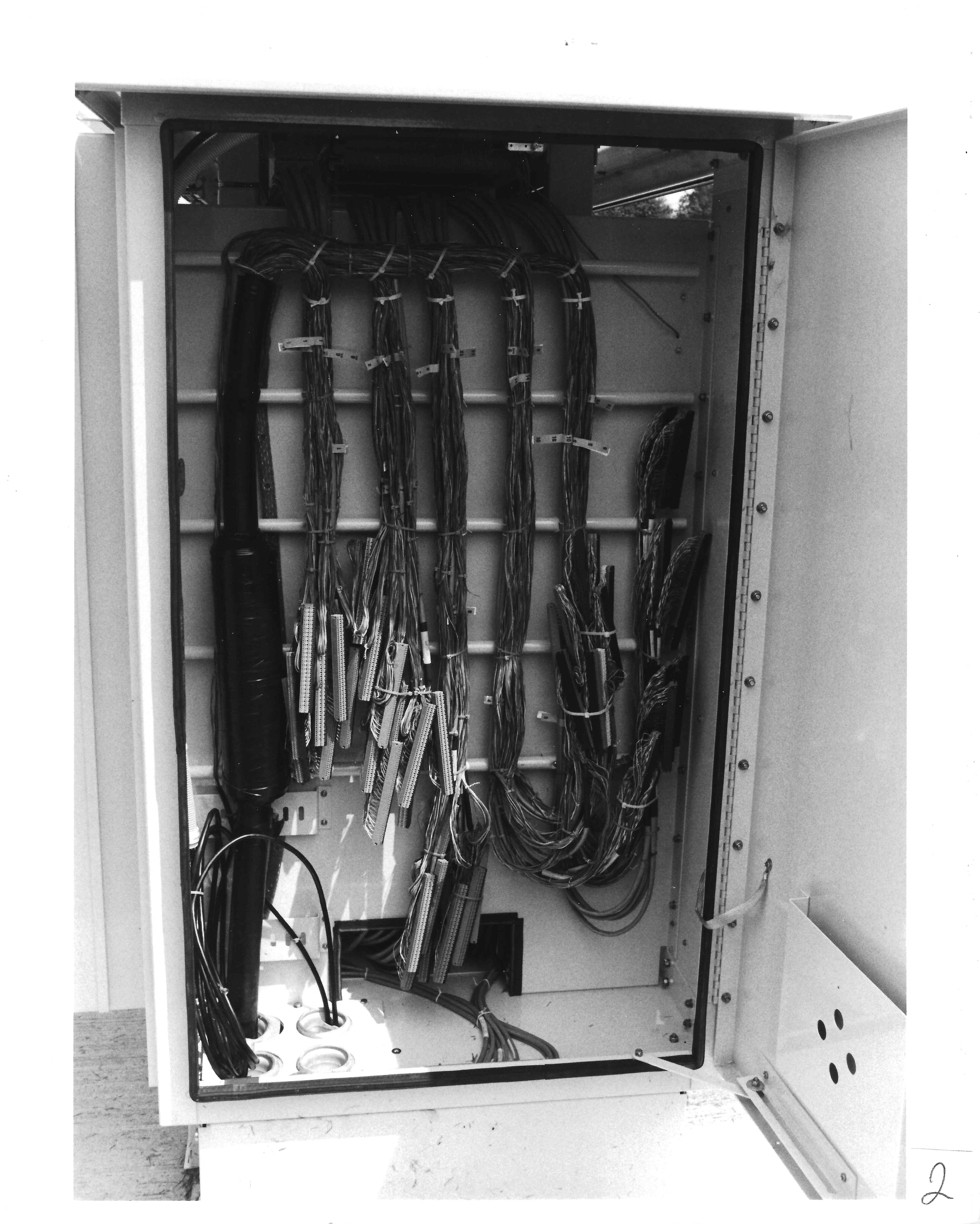
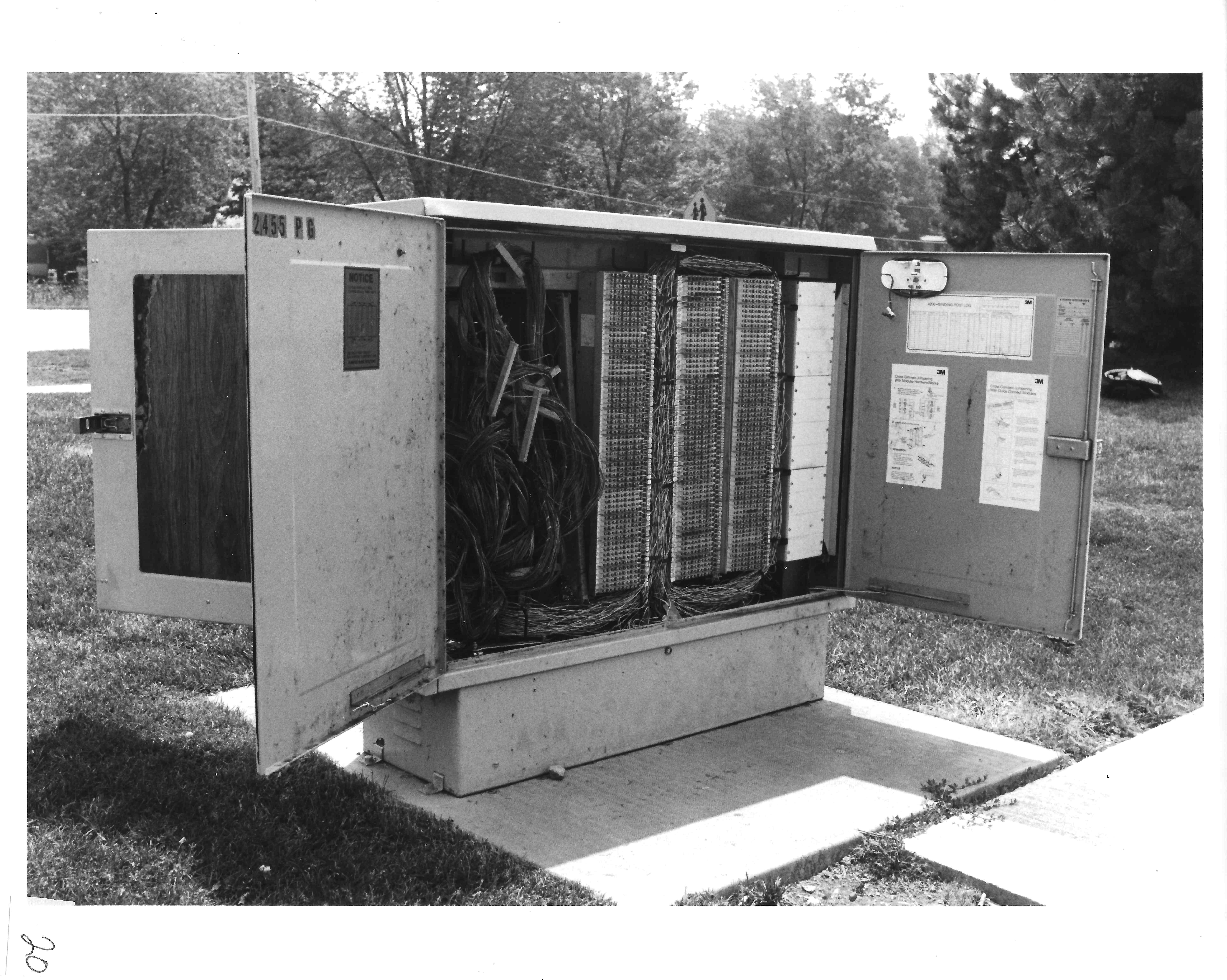
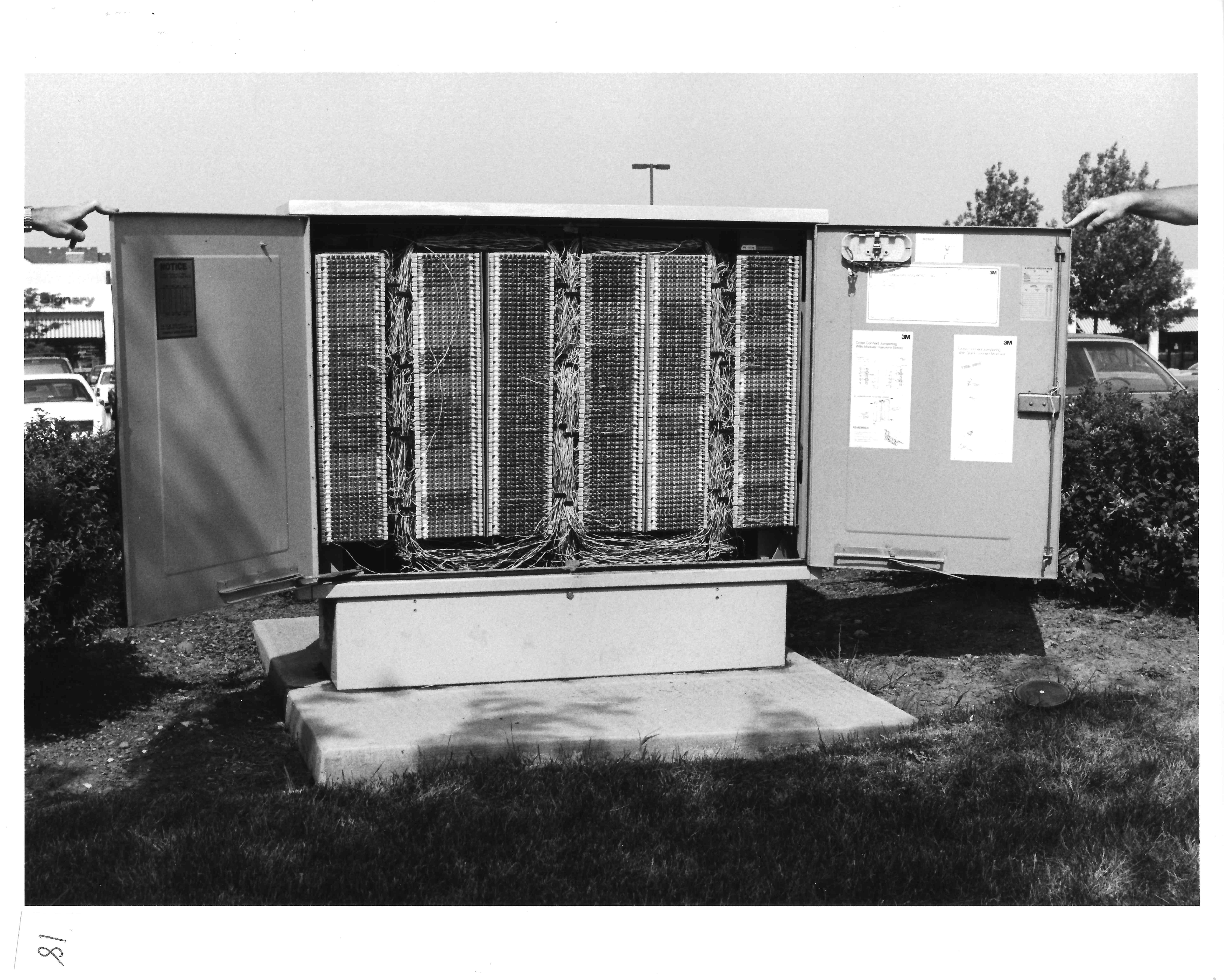 Opened cross-connect box.
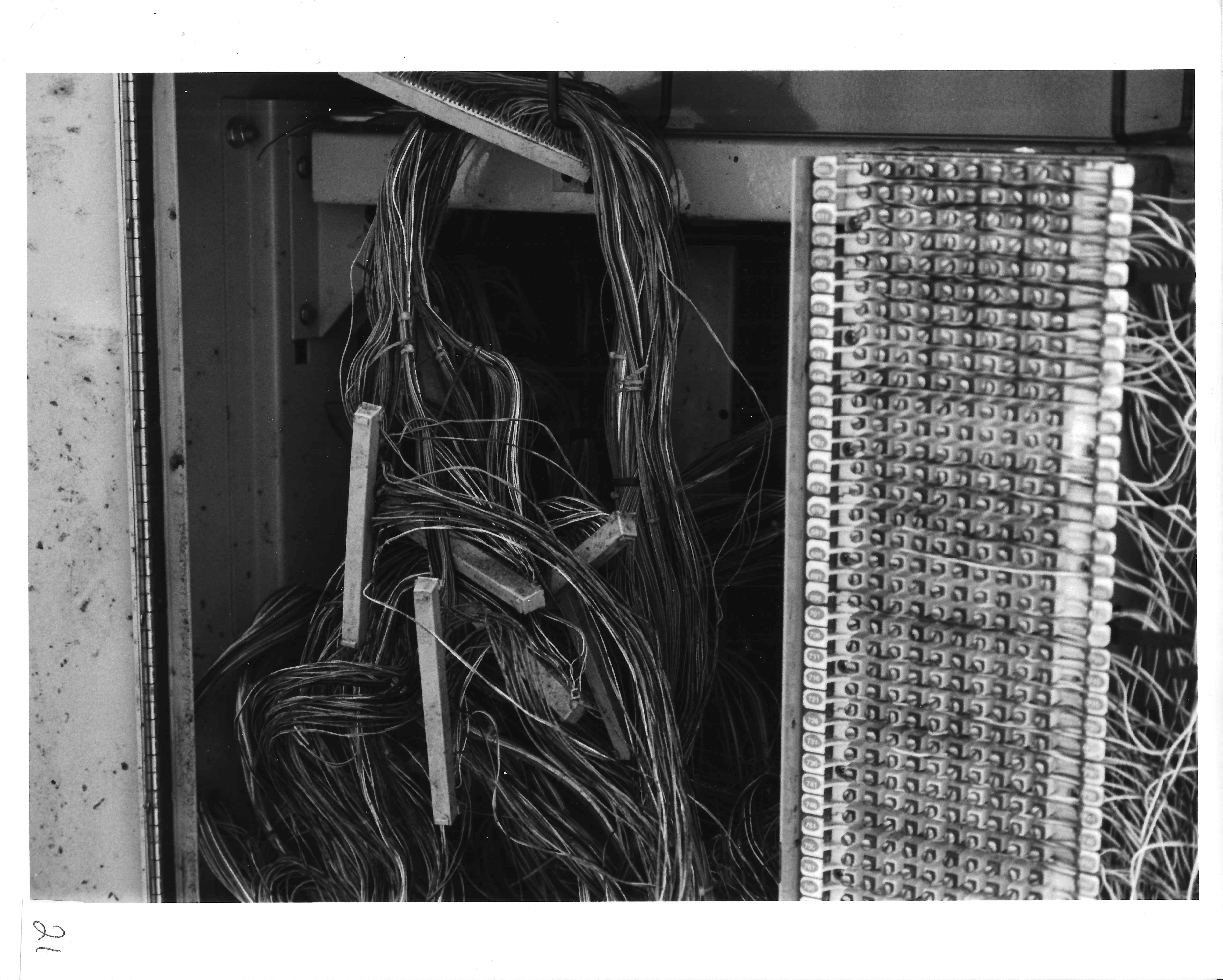
Inside a cross-connect box.
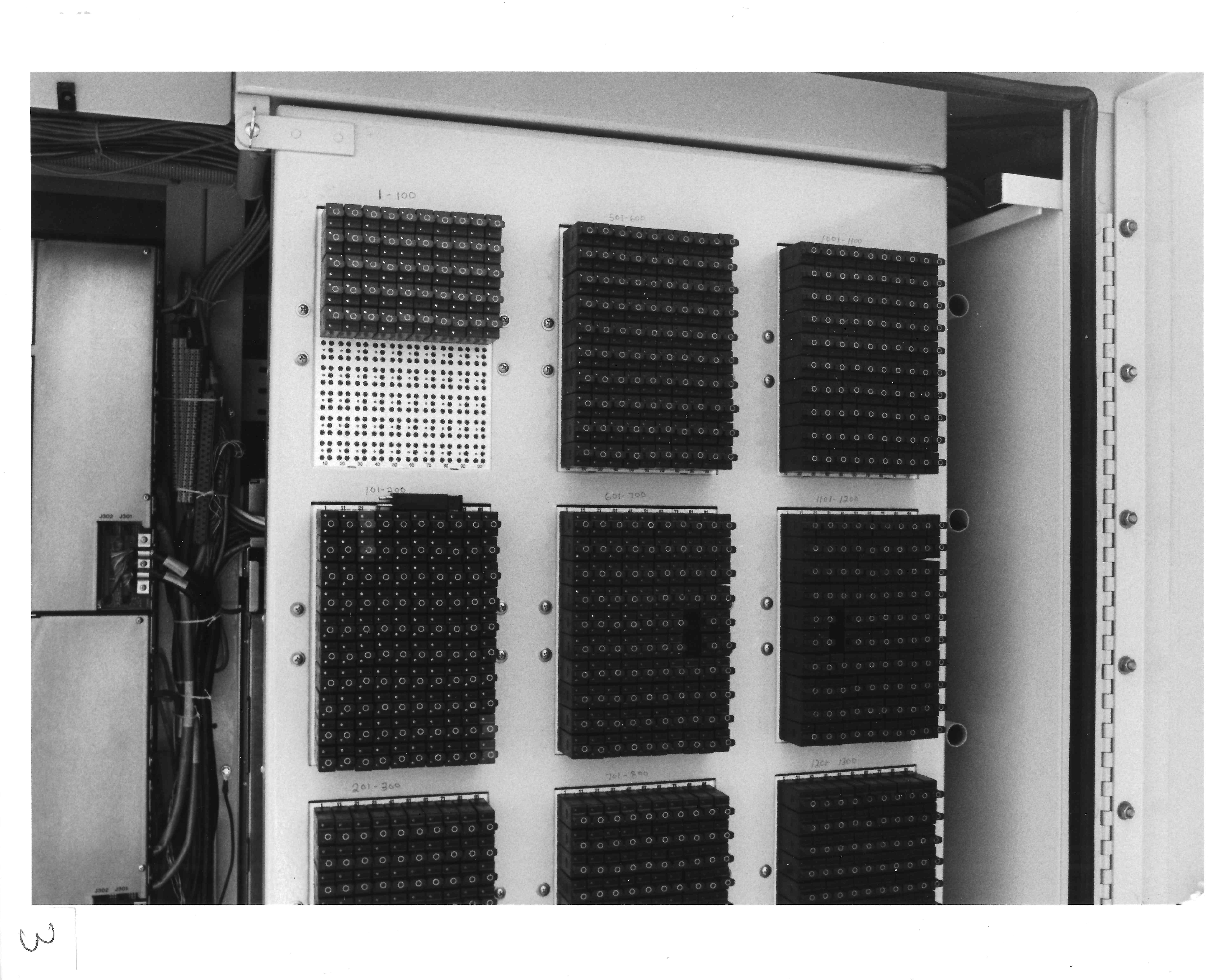
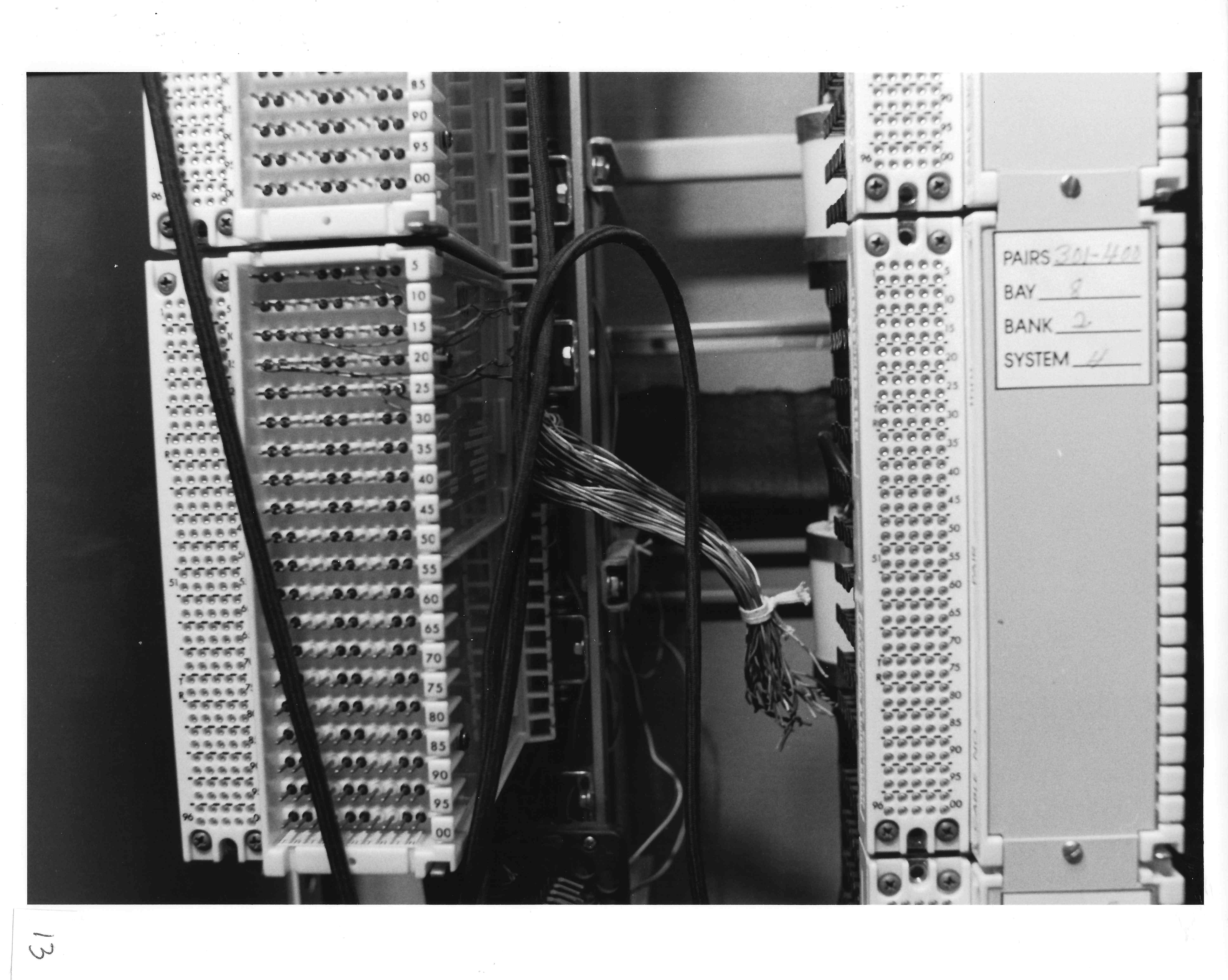
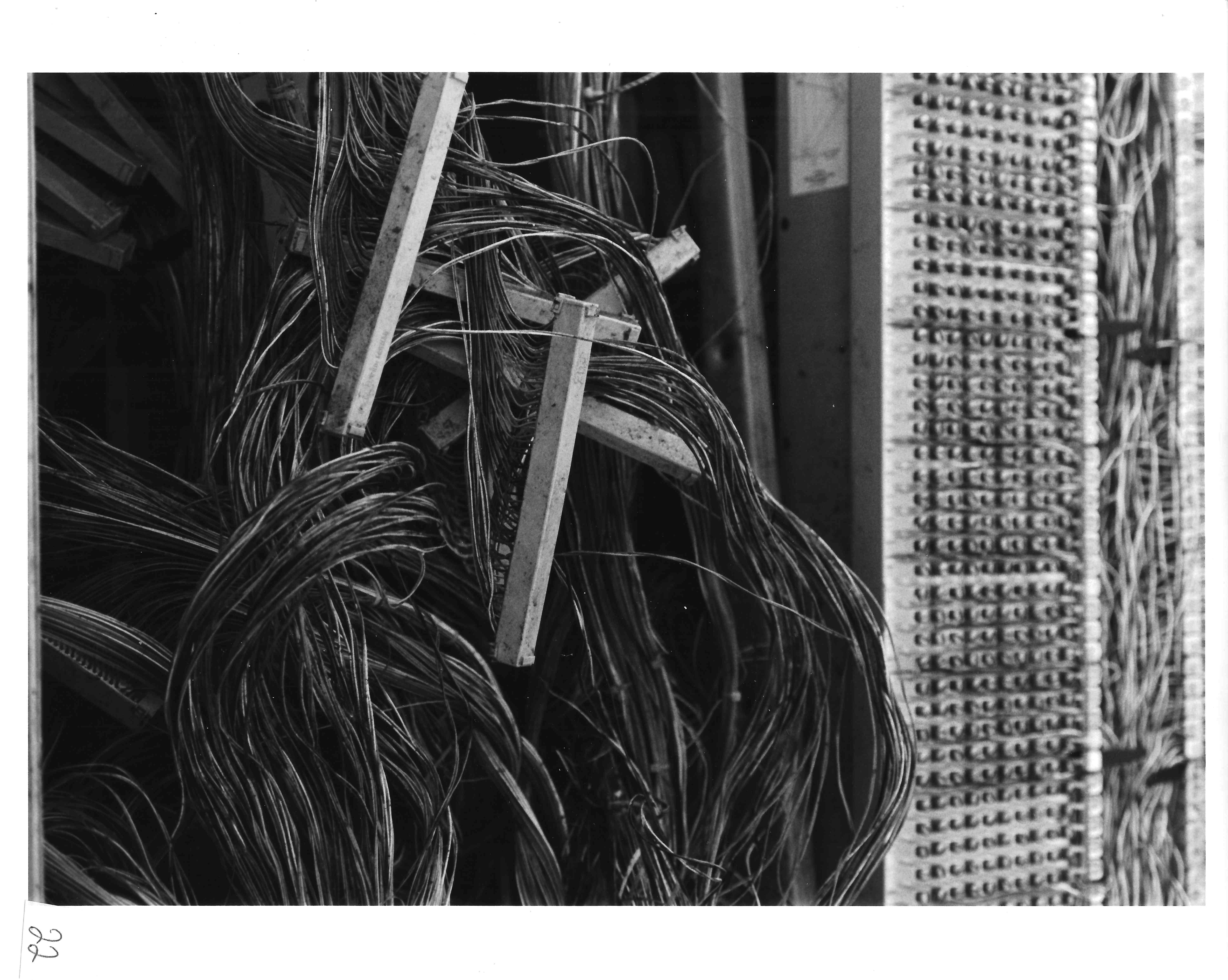
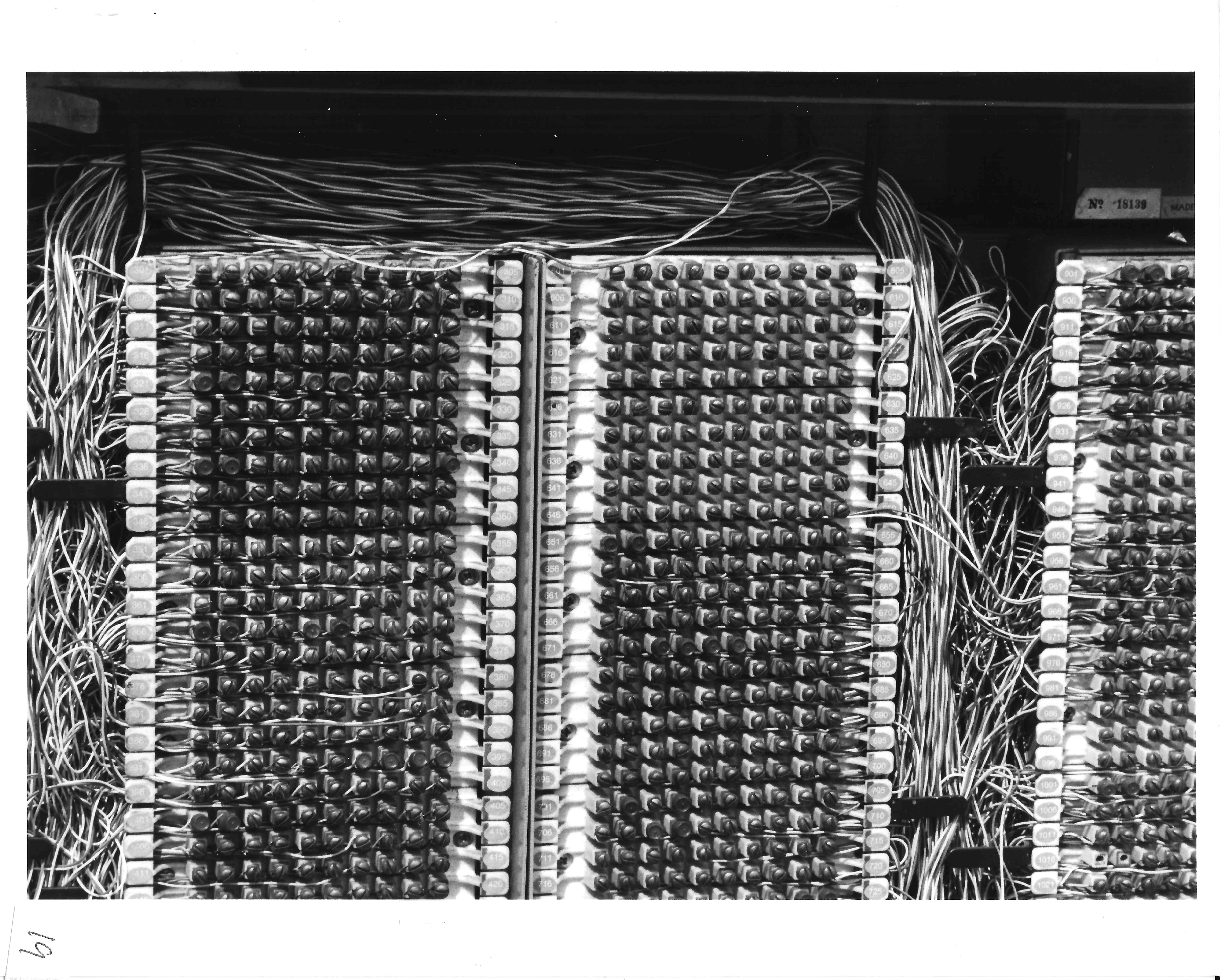 Connection blocks.
Individual wires are used to connect feeder pairs to the appropriate local distribution pair. A closer view of these connection blocks is shown above. If you examine it closely you can see the individual wires connected to the screws. Other cross-connects use "punch-down" terminals.
 Back of cross-connect box.
The back of the cross-connect box.
 Splices in the box.
Located behind the connecting blocks are splices which connect the feeder and distribution cables to their associated connecting block.
 Splices in the box - different angle.
Splices from a different angle. Although obscured by the wiring and splices, the rear of the connecting blocks on the opposite side of the cabinet are located immediately behind the splices. Additional connecting blocks are located to the right of the cable splices.