 .:: Railgun 01 ::. .:: Railgun 01 ::.
|

Introduction:
I found a great explination of what a railgun is and a simple explination of how one functions on Wikipedia and hence quote their great description,
"A railgun, also known as a Gauss gun, is a form of gun that (unlike many others) converts electrical energy into projectile kinetic energy, rather than the more conventional chemical energy from an explosive propellant.
The theory and construction of a railgun are quite simple at first sight, but horribly complex beneath.
An electrical current, when in a magnetic field, experiences a force perpendicular to the direction of the current and the direction of the magnetic field. This is the principle behind the operation of an electric motor, where fixed magnets create a magnetic field, and a coil of wire is carried upon a shaft that is free to rotate. When electricity is applied to the coil of wire a current flows, causing it to experience a force due to the magnetic field; the wires of the coil are arranged such that all the forces on the wires act to make the shaft rotate, and so the motor runs.
A railgun is even simpler than a motor. It consists of two parallel metal rails (thus the name) which are slotted on the inside so that a metal projectile can slide between the rails. At one end, the rails are connected to an electrical power supply. When the projectile is inserted between the rails (from the end connected to the power supply), it completes the circuit. Electrical current runs from the positive terminal of the power supply up the positive rail, across the projectile, and down the negative rail back to the power supply again.
This flow of current makes the railgun act like an electromagnet, creating a powerful magnetic field in the region of the rails up to the position of the projectile. But since the rails and projectile are carrying an electrical current through this magnetic field, they experience a force; and it so happens that when you run through the maths, the force is trying to push the rails and projectile outwards. Since the rails are firmly mounted they cannot be pushed apart, but the projectile is able to slide up the rails away from the end with the power supply.
If you happen to do this with a very large power supply, providing a million amperes or so of current, then the force on the projectile will be tremendous, and by the time it leaves the ends of the rails it can be travelling at many kilometres per second.
The complexity in railgun design comes from:
1. The need for strong conductive materials to build the rails and projectiles from; the rails need to survive the violence of an accelerating projectile, and heating due to the large currents involved and friction. The force exerted on the rails consists of a recoil force - equal and opposite to the force propelling the projectile, but along the length of the rails (which is their strongest axis) - and a sideways force caused by the rails being pushed by the magnetic field, just as the projectile is. The rails need to survive this without bending, and be very securely mounted.
1. Power supply design. The power supply must be able to deliver a large current for a tiny amount of time, so capacitors and compulsators are both being pursued; most other power supplies are designed to provide constant power levels for long periods, which is a very different design requirement.
1. Electromechanical design. What is the optimum distance between the rails, the optimum size of the rails, and the optimum shape for the projectile? The shape of the conductors influences the shape of the magnetic field. Ideally, the magnetic field should be as strong as possible in the region of the projectile in order to get the most acceleration. But anything that makes the conductive path longer increases its resistance, and so less current flows. Computer simulation and physical experimentation are being used to try to find optima.
Table of contents [showhide]
1 Railguns as weapons
2 Railguns in science fiction
3 Peaceful uses of railguns
4 Further Reading
4.1 Theory
4.2 Practice
Railguns as weapons
Railguns only fire bullets, not shells. Shells depend on their arrival at the target being more violent than their launching, so they can be detonated by impact without detonating in the barrel of the gun. However, being fired from an anti-tank railgun can be more violent than hitting a tank (the projectile accelerates to maximum velocity in the space of a metre or two, but when it hits the tank it punches straight through and decelerates for several metres), so the detonating mechanism for a shell would have to be fairly complex (and thus expensive, and prone to failure in dangerous ways). The railgun is still an effective weapon as the raw kinetic energy of a railgun projectile will not only punch through armour plating with impunity, it will spray vaporised metal carried on a sizeable shock wave which incinerates the interior of the target (and any occupants) - see KE-penetrator
One could construct a low-velocity railgun that fired shells, but there seems to be little interest in doing so to date; existing chemical propellant systems have that niche quite securely filled, although it is perhaps likely that future railgun artillery would also have a low-velocity shell firing mode for indirect fire and delivering chemical or biological payloads.
The United States military is funding railgun experiments. At the University of Texas' Centre for Electromechanics, military railguns capable of delivering tungsten armour piercing bullets with kinetic energies of nine million joules have been developed. [1] Nine million joules is enough energy to deliver a kilogram of projectile at three kilometres per second - which will tear a tank to pieces in a single shot.
Due to the very high muzzle velocity that can be attained with railguns, there is interest in using them to shoot down high-speed missiles.
Naval forces are interested in railgun research, too. Current ship guns sit on top of a large room called a magazine, which is full of shells for the gun to fire. If a shell from a hostile ship should happen to penetrate into the armoury and explode, it is quite likely to cause all of the shells in the magazine to detonate, usually destroying the ship. However if the ship is instead equipped with railguns, all it needs to store to feed the gun are the tungsten bullets, which are much more compact than shells - and the electricity can be supplied from the ship's engines, perhaps buffered in capacitors. These things will explode much less violently than a room full of shells if hit.
Railguns in science fiction
Railguns have started to appear in sci-fi and become a mainstream idea. However, they have been portrayed somewhat inaccurately.
In the film Eraser, the lead character gets hold of a device like a chunky rifle that is said to be a man-portable railgun. It is shown firing bullets through great numbers of walls and so on, and it makes a blue trail in the air. The popular computer game Quake II features a very similar device.
However, man-portable railguns will not be revolutionary weapons; if power supply technology ever lets us make a railgun supply small enough to be carried then rail-handguns will probably only be able to fire projectiles at speeds not much higher than currently achieved with chemical propellants. The simple reason is that the destructive power of a handgun or long gun is limited as much by recoil as anything else; we can quite happily build a handgun that fires 20mm cannon shells, but you couldn't fire it without having your hand broken.
One possible route to explore is a portable railgun that fires very small bullets. The recoil of a weapon is caused by the momentum of the escaping projectile yet the damage done by the projectile is more related to its kinetic energy. The momentum of the projectile is its mass times its velocity, but the kinetic energy is one half of the mass times the velocity squared. So a very small, very fast, projectile could deliver a moderate recoil, but be carrying enough kinetic energy to vaporise upon impact and burn a large hole in armour and flesh alike. However, such a weapon would not fire through walls very well; the projectile would vaporise upon contact with the first wall. See needlegun.
Peaceful uses of railguns
There is interest in using railguns as mass drivers for space exploration and mining. They would be useful for launching bulk ores into space, particularly from low-gravity bodies such as moons and asteroids; electrically powered from solar panels, they would not require any consumables such as rocket fuels.
Also, railguns may be used to initiate fusion reactions, by firing pellets of fusible material at each other. The impact would create immense temperatures and pressures, allowing nuclear fusion to occur. However current railguns are not yet sufficient to achieve the energies required."
|
The purpose of my project is to construct an amateur railgun improving upon existing amateur railgun designs. Some key factors I will focus on are rail corrosion, projectile type, pulse shape, muzzle flash reduction and device size.
Injection system - No injection system will be used for this railgun design. The initial vaporization of the back of the projectile will cause high pressure to be present in the chamber behind the projectile. This will keep the projectile moving along the rails without welding and will increase efficiency by recycling energy from the capacitors which would normally be lost. In contrast, most other railguns produce pressure in front of the projectile which slows the armature down.
Power Source - Compulsators are the way to go when a high power railgun is to be constructed however my budget is limited and an alternate method must be chosen. There are not many other options when it comes to a railgun power supply and capacitors are the inexpensive way to go. Luckily I was able to obtain a sponsorship from Cornell Dubilier (CDE) of 10 450V 6,300uF (6.4kJ total) electrolytic pulse rated (25kA peak) capacitors. Using electrolytic vs oil filled allows for much greater energy density and will allow the railgun chassis to be relatively small.
Projectile - My projectile will consist of a dielectric such as delrin, which is a type of plastic, with a thin layer of conductive material on the back. The railgun will use a plasma armature to push the projectile forward and will also use the pressure from the armature vaporization which will occur behind the projectile.
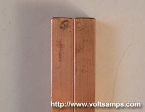
Rails - The rails will consist of two parallel copper alloy 110 bars. The bars will be electrically spaced so that arcing will not occur at the intended maximum voltage of 4.5kV. I had initially planned on using tungsten alloy rods, due to their very high melting point, as the rail contact area, however the price was out of my budget and rail erosion will have to be reduced via other methods. Using a plasma armature will prevent the depositing of projectile material on the rails. The rails will be small, cheap, and modular; requiring minimal machining.
Muzzle - Rail guns have been known to spray a shower of sparks in the direction of aim as peices of molten rail and projectile are forced out by gas pressure and the glowing projectile itself. This makes optical speed readings difficult. Most machine guns today have muzzle flash suppresors for reducing the muzzle flash from lengths of upto 4 feet down to about 10 inches. The idea is to redirect the gasses to the sides as the projectile leaves the barrel until there is not enough pressure to cast a giant stream of fire. Using dielectric projectiles also solves the problem of my projectile glowing in flight.
Progress:
Because of the large total number of images and comments compiled during the construction phase I posted all the construction details on a separate page which can be accessed HERE.
Shot 01:
Velocity: >24 m/s
Capacitor Energy: 5 kJ
Projectile Energy: >0.26 J
Efficiency: >0.0052%
Comments: Because the projectile had an inelastic collision with the pendulum, only a lower bound reading could be made. The projectile bounced off of the pendulum taking with it the remaining momentum. The reason the projectile did not penetrate the apple is credited to the bellow freezing temperatures currently in New York. The apple hung overnight and froze solid before the test shot. The second shot will use a softer substance in order to achieve an inelastic collision.
Variables:
Mprojectile = 0.9 gm
Mpendulum = 213 gm
Lpendulum = 61 cm
Delta X = 2.5 cm
Delta Y = (61 cm) - (cos(sin-1((2.5 cm) / (61 cm))) * (61 cm)) = 0.053 cm
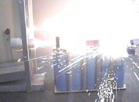
Videos:

 railgun-01.mpg (5.22MB) railgun-01.mpg (5.22MB)
| Cammera 01 | Cammera 02 |
| Frame 01 | 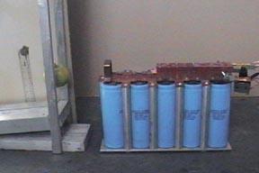 | 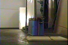 |
| Frame 02 | 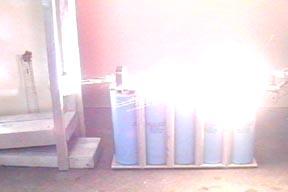 | 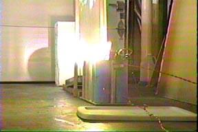 |
| Frame 03 | 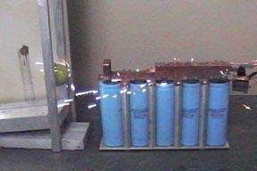 |  |
| Frame 04 | 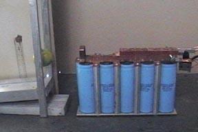 | 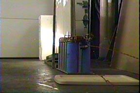 |
Images:

Rail errosion from the plasma armature. Thanks to the plasma armature, the damage to the rails was very minimal and the rails are ready for the next shot.
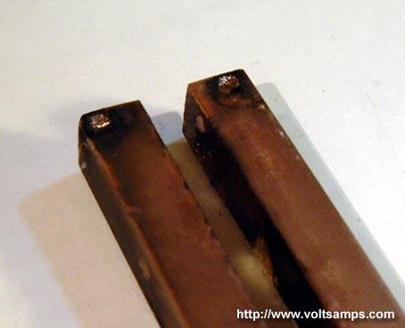
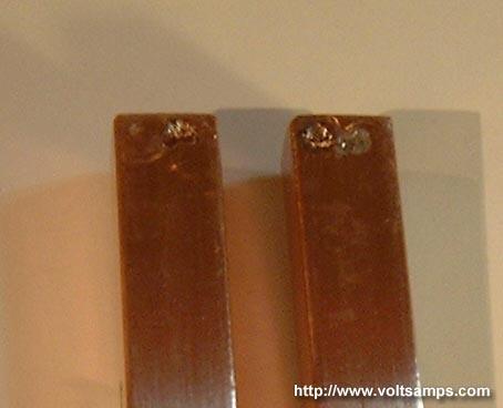
The spot weld marks from the rail clamps/terminals.
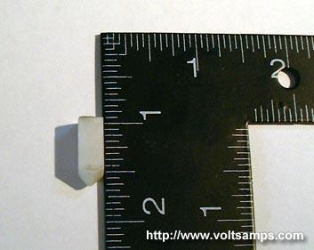
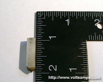
0.9 gram Delrin projectile.
Shot 02:
Velocity: 30 m/s
Capacitor Energy: 5 kJ
Projectile Energy: 1.04 J
Efficiency: 0.0208%
Comments: The second shot was very exciting because it would be the shot which told me exactly the railgun output. My ballistic pendulum setup now used a PVC container filled with gelatin which would guarantee an inelastic collision. The video shows the projectile lodging into the pendulum. You will also see a plastic spacer flying out of the projectile. Apparently, the spacer, which fills the gap behind the projectile, has compressed from the foil vaporization and shot out after the projectile. My mercury contactor which triggered shot 01 had internally failed and I was forced to manually trigger the railgun setup. Armed with welding goggles, ear plugs and a long stick I fired the railgun, which was a pretty frightening experience. After both videos were captured I was able to calculate a rough velocity, kinetic energy and efficiency using a ruler as a distance reference, a video editing program, and then an image editing program to make pixel-accurate distance measurements. Looking over the videos I noticed that there was much energy loss due to sparking and gasket leaks which isnt a big deal on this railgun prototype, however tighter machining tolerances will improve efficiency by a huge factor.
Variables:
Mprojectile = 2.3 gm
Mpendulum = 304 gm
Lpendulum = 64 cm
Delta X = 5.7 cm
Delta Y = (64 cm) - (cos(sin-1((5.7 cm) / (64 cm))) * (64 cm)) = 0.258 cm
Videos:
railgun-02.mpg (4.94MB)
| Cammera 01 | Cammera 02 |
| Frame 01 | 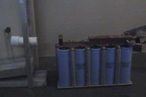 |  |
| Frame 02 | 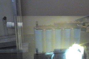 | 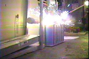 |
| Frame 03 | 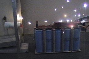 | 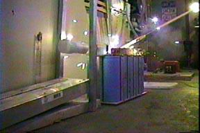 |
| Frame 04 | 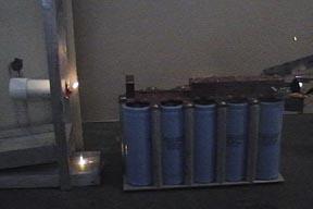 | 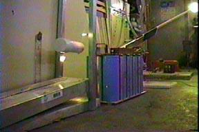 |
| Frame 05 | 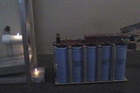 | 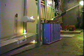 |
Images:
2.3 gram Delrin, steel core/tip projectile. This projectile is sharper than the previous and has a steel core for a higher mass.
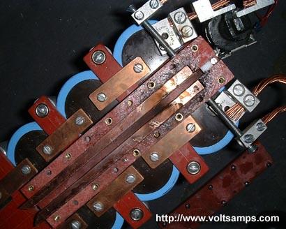
This is the top view of the rail enclosure after the shot. You can see signs of gasket leakage where the fiber glass enclosure is blackened.
This is the damage done to the rails after the second shot. The rails have not yet been cleaned.
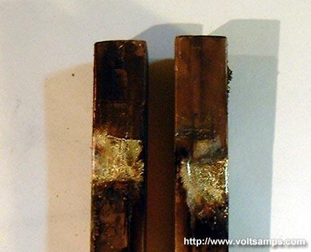
This is the damage done to the terminal clamp portion of the rails before the rails were cleaned.
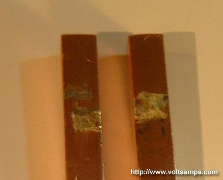
After cleaning the rails (not using steel wool or sand paper) you can see that the damage isn't at all as bad as it seemed, and the rails can be used over and over again. In a field version of this railgun the rails can be quickly and easily cleaned with some kind of steel wool and cloth material that can be pulled through the barrel.
This second shot shows that using graphite to improve terminal coupling with the rails wasn't a good idea as it caused more damage to the rails than the first shot. Graphite has somewhat of a high resistance and possibly vaporized during the current pulse.
Conclusion:
I wish I could do more experimentation and research in order to provide more detailed data and a more optimal design however I am sponsored for only the capacitors and the rest comes out of my own pocket. I believe that I can make many conclusions based on the shots fired, the data and visual observation despite the fact that my time and resources were heavily limited. As far as rail erosion it is clear that plasma armature causes much less damage to the rails than a conductive projectile. I was able to utilize both Lorenz force and thermal expansion forces to accelerate a projectile from a dead stop to relatively high speeds. By avoiding the use of an injector I lowered my railgun efficiency however was able to make scientifically accurate measurements and calculations. One factor which I believe would increase the efficiency by a large amount is tighter machining tolerances. When the channel was machined for the projectile to slide through, a clearance was added so that the projectile would not get stuck down its path through the rails; however this allowed the plasma to shoot past the projectile and also allowed the pressure to seep around the edges of the projectile. You can see evidence of this in the projectile photo from shot 02; there are scratch marks and aluminum particles fused to the projectile walls which are a clear indicator. Another factor that would increase efficiency was the gasket quality between the top portion of the rail stack and the bottom half. From the frame-by-frame shots you can clearly see gasket leaks which would also allow pressure to escape. Tighter machining tolerances should alone yield efficiencies that are more than 10 times that of shot 02. The rail length and projectile mass also play a major role and must be optimized. Railguns have great potential and have many military applications, but seem somewhat impractical at low energy levels unless used for research such as this one. Overall, I learned a lot from this project and got a better feel for working with extremely high power levels, and learned lots about machining. I am not looking into future railgun research (at these reletively low energy levels) because it isnt practical or useful for any application at this scale, except for maybe a glittery light show.
|
 |
|


 IP LOGGED: