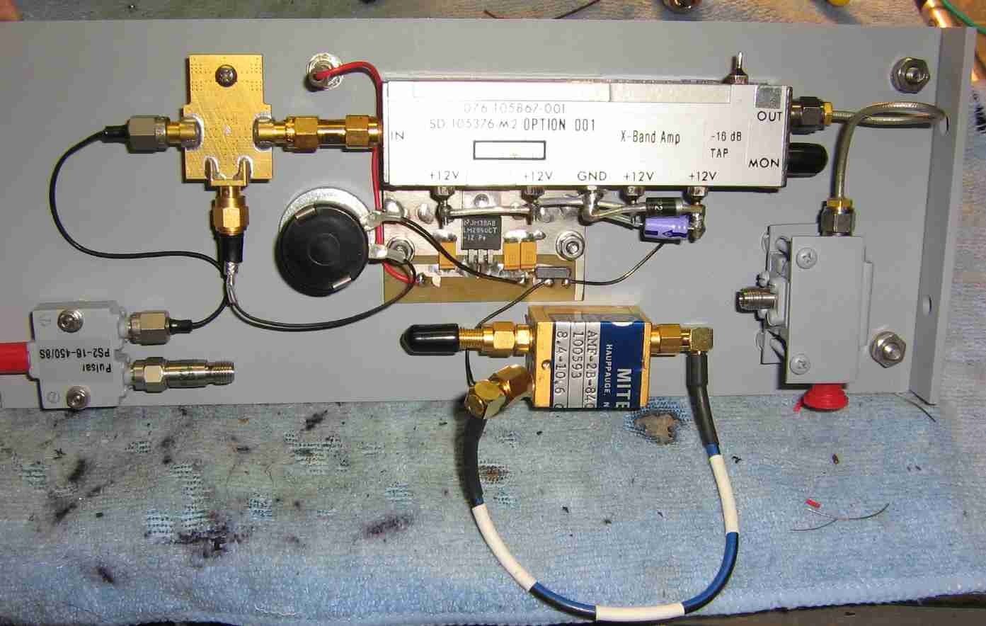
General overview of the X-band RF power amplifier and output circulator stage for the interferometer.
A Pulsar PS2-16-450/8S 2-way, 0° RF splitter is on the lower-left.
This splits the output of the 8.37 GHz transmitter oscillator into two paths. One path is further amplified and radiated, the other is sent to a mixer to form the REFERENCE 70 MHz IF signal.
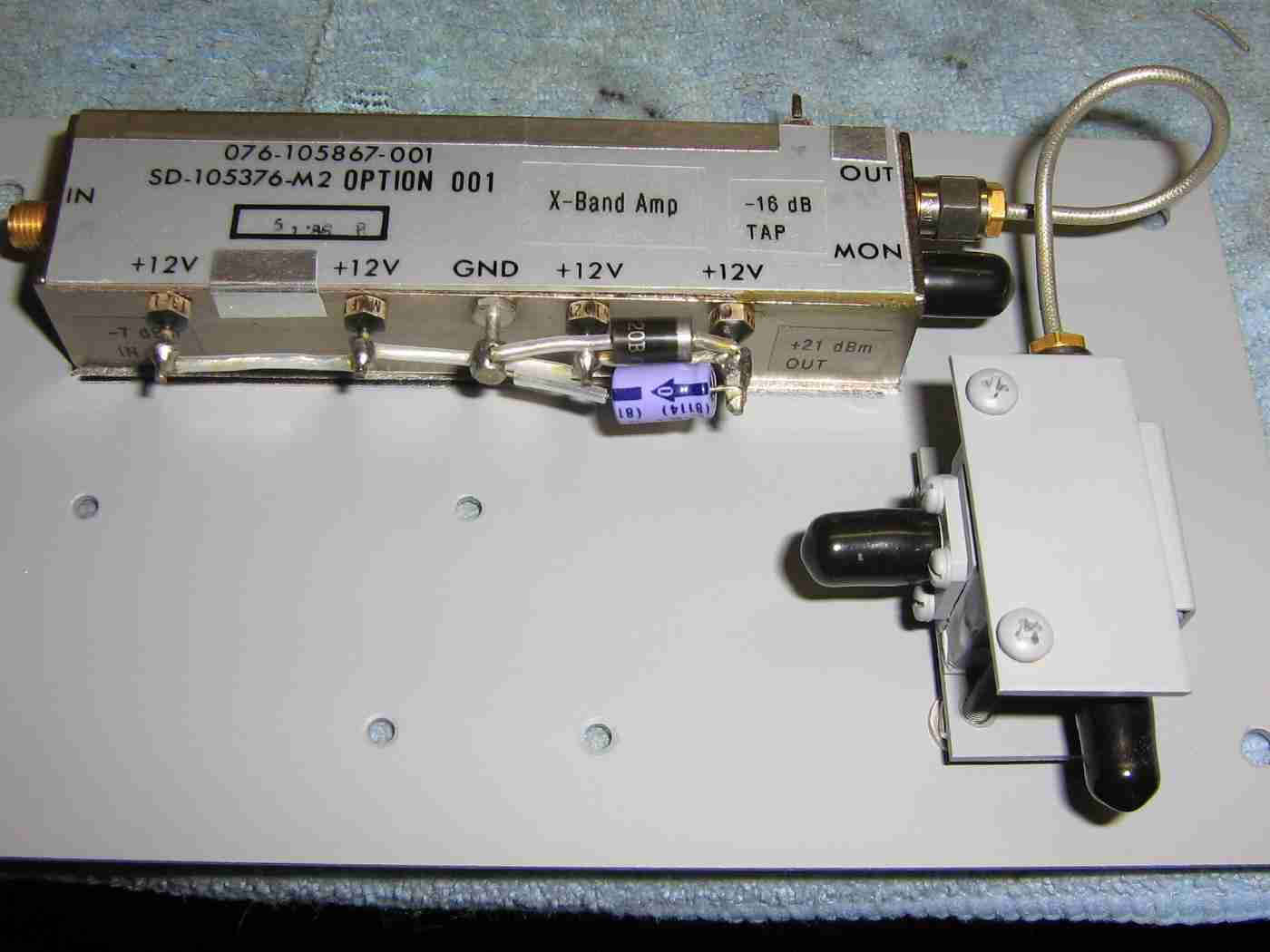
Overview of the X-band RF power amplifier section.
It is labeled SD-105376-M2 and was made by Harris/Farinon. It was most likely a pre-driver stage for a higher power amplifier. The RF output power is around +20 dBm for a 0 dBm input signal. It requires +12 VDC at around 500 mA.
There is a "MON" tap which provides a -16 dBc tap for monitoring the output RF signal.
On the output of the RF power amplifier is a standard X-band 3-port ferrite circulator. RF input (from the power amplifier) is on the circulator's port 1. The antenna connection will be on port 2, and port 3 goes to the receive stage.
When using higher RF carrier power, it is best to use separate transmit and receive antennas for maximum isolation between the two stages.
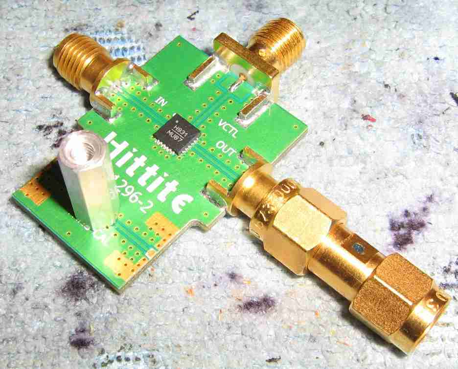
On the input to the RF power amplifier is a phase shifter.
This is optional, but is useful to nullify any phase difference introduced in the other RF stages.
Shown is an evaluation board for a Hittite HMC931 X-band analog phase shifter. This phase shifter is essentially "passive," requiring only a 0-12 VDC tuning voltage to control the phase shift. RF input to the phase shifter should be under +10 dBm to prevent compression artifacts or phase distortions.
The Hittite HMC931 has only three connections; RF input, RF output, and the voltage control.
A 1000 pF capacitor should be added on the evaluation board from the voltage control line to ground.
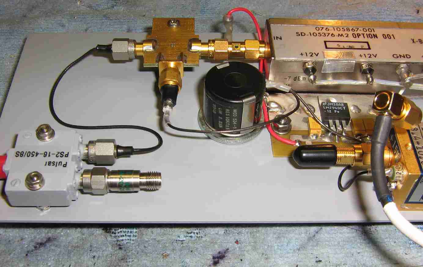
Overview of the installation of the phase shifter.
A LM2940-12 low-dropout voltage regulator provides a clean source of +12 VDC for the RF power amplifier, the phase shifter control, and the receive pre-amplifier.
The 10 kohm multiturn potentiometer is for the phase shifter's control voltage. A 0 to 10V voltage control gives an approximate 0 to 360° phase shift.

Overview of the optional low-noise receive pre-amplifier.
It's a Miteq AMF-2B-840106-45 and provides around 20 dB of gain over 8.4 to 10.6 GHz.
It's designed to work at +15 VDC, but it appears to work fine at +12 VDC.
A similar X-band receive pre-amplifier project was described in GBPPR 'Zine, Issue #79 using a HughesNet/DirecPC NJR2117FJ satellite block downconverter.
Low-quality receive pre-amplifiers can be driven into compression, distorting or increasing the noise on the received signal.

Overview of the 8.3 GHz local oscillator source and mixer stages.
The 8.3 GHz local oscillator source on the right is a Delphi Components DI083-03 "brick" oscillator.
This oscillator uses an internal 100 MHz crystal reference source and provides a very clean RF output signal at around +17 dBm. It runs at +15 VDC and draws a little over 1 amp.
There is an optional isolator on the output of the brick oscillator so it always "sees" a 50 ohm load.
The local oscillator is split into two paths using another Pulsar PS2-16-450/8S 2-way, 0° RF splitter. Try to keep the RF paths of the two local oscillator sources equal in length.
The two RF mixers are REMEC Magnum MC76PR-3. These mixers are not designed for operation at this frequency range, but quality microwave mixers are difficult to find and very expensive.
The specifications for the REMEC Magnum MC76PR-3 mixers are:
  RF: 13.8 - 14.7 GHz
  LO: 11.8 - 14.0 GHz at +13 dBm
  IF: DC - 2 GHz

Alternate view of the 8.3 GHz local oscillator source and mixer stages.
The two panel-mount SMA connectors on the lower-left are for the REFERENCE and SIGNAL outputs for the AD8302 phase detector.
An external 70 MHz IF amplifier can be used on the SIGNAL output.
The output from the AD8302 phase detector can be displayed on a common oscilloscope for testing purposes. The AD8302 outputs 10 mV per degree of phase difference between the two input signals.
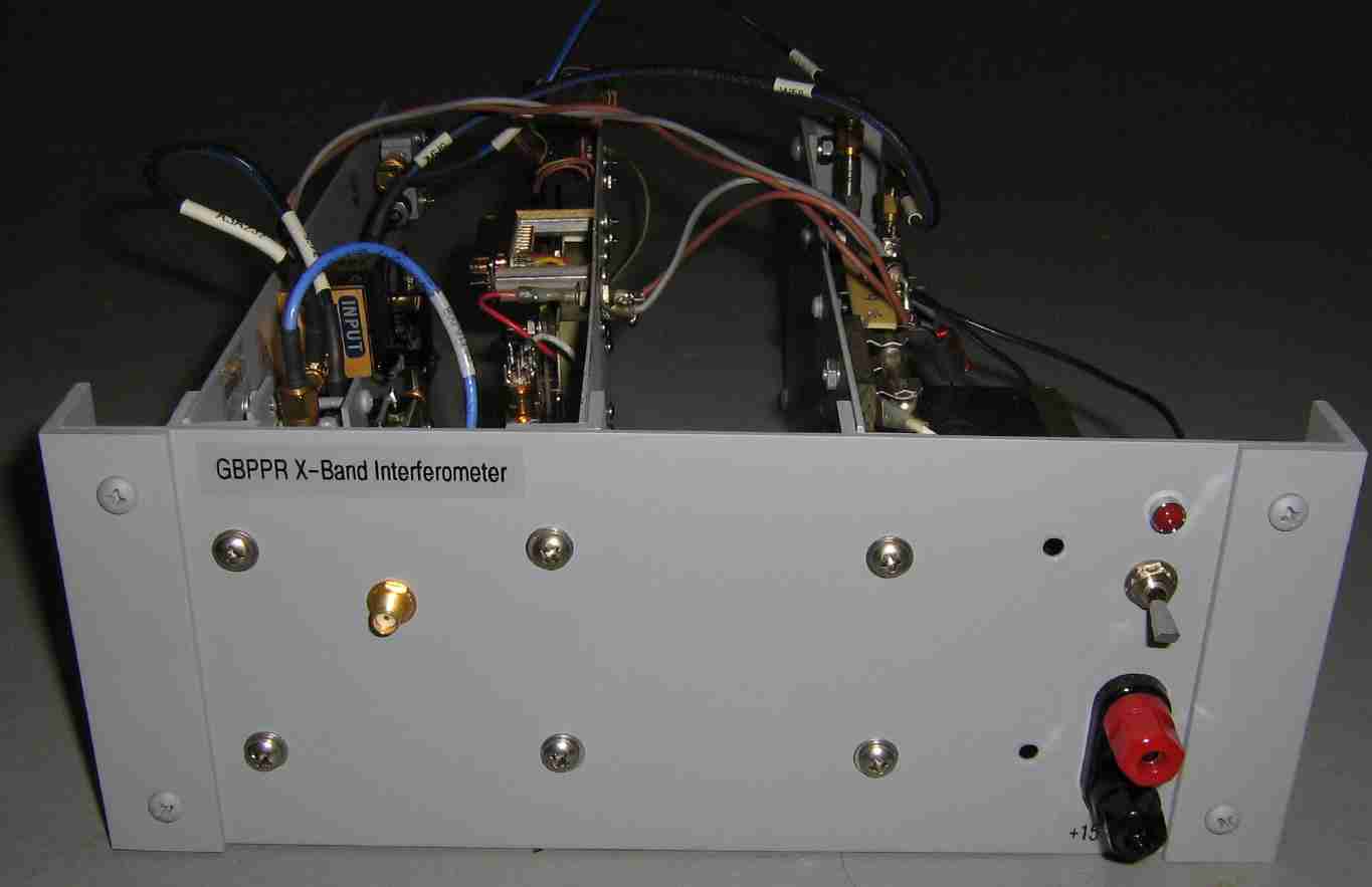
Front-panel overview of the experimental GBPPR X-band interferometer.
The banana jacks on the lower-right are for the +15 VDC power input.
The SMA jack on the left is for the antenna connection.

Alternate view.
The Stellex YIG project described eariler provides the 8.37 GHz transmitter oscillator source.
The panels are made from K&S Metals aluminum sheet stock (#257).

Alternate view.
A SPST power switch, 2 amp fuse, and protection diode were added on the +15 VDC input.
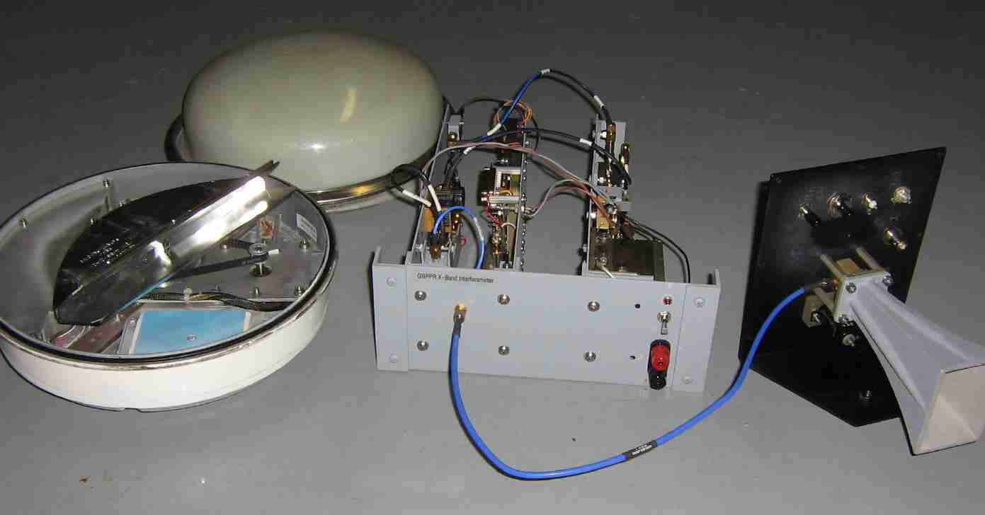
Example antenna systems overview.
For fixed targets, a standard X-band horn antenna can be used.
For counter-UAV applications, the rotating antenna assembly from a Qualcomm OmniTRACS unit will be utilized. This is still experimental and will be discussed further in upcoming projects.