Piezo contact probe.
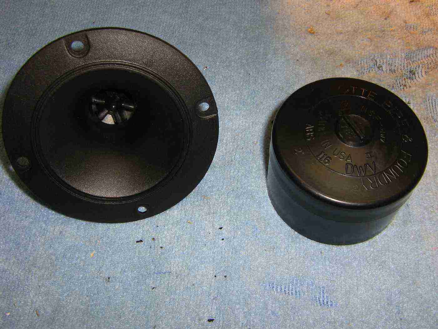
A common piezo horn tweeter is shown on the left and a 2-inch ABS plastic cap is shown on the right.
The piezo horn tweeter will be mounted inside the 2-inch cap to act as a handle. This is optional, but recommended.
Piezo horn tweeters can be used as a "poor man's contact microphone" by placing them against the target wall or item to be monitored.
They can then be "fixed" in place using common rubber cement, rope caulk, or removable putty adhesive like Elmer's Poster Tack.
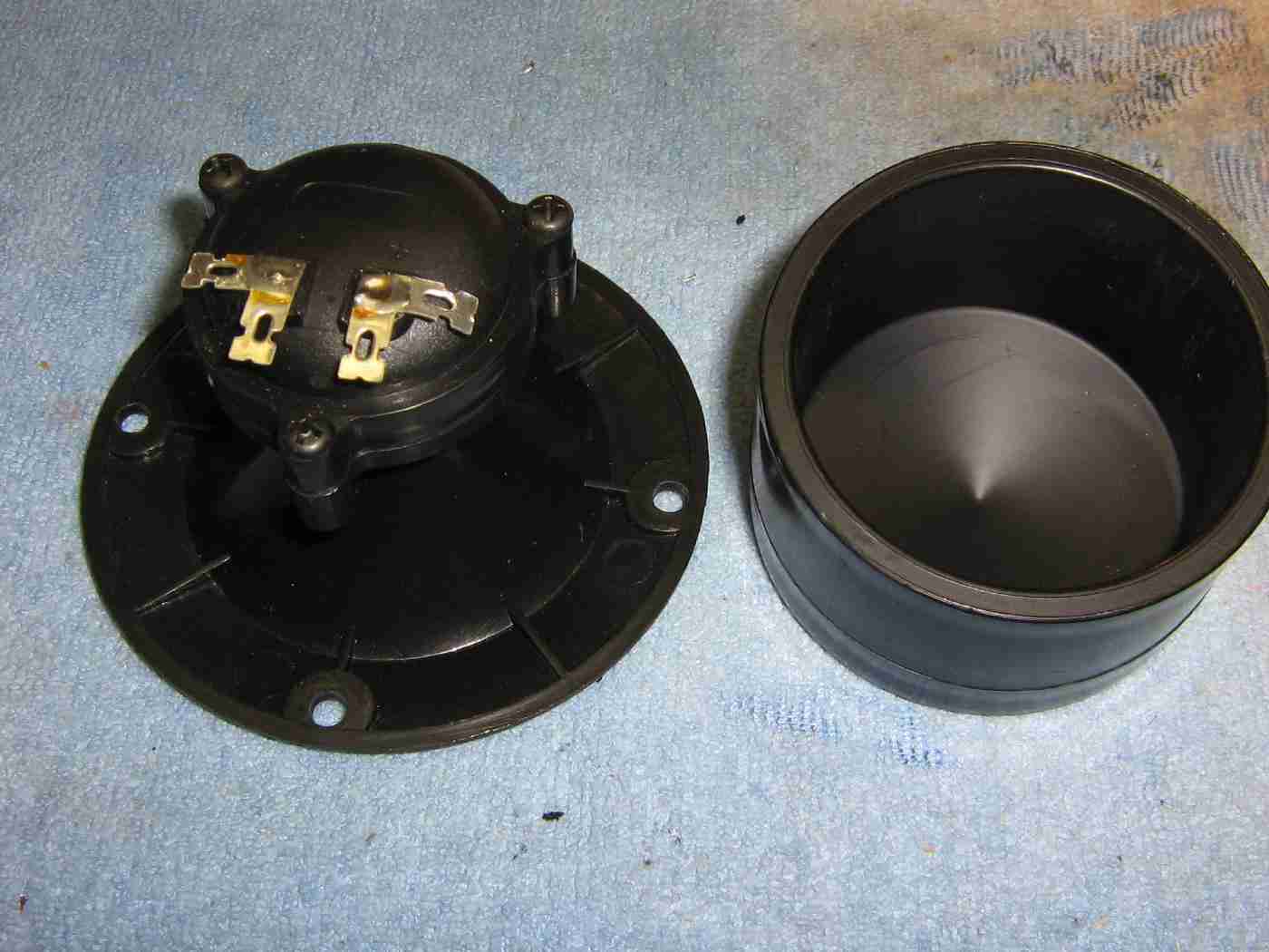
Rear view of the piezo horn tweeter showing the contacts.
The tweeters are polarized, so the "+" terminal will go the input of the amplifier circuit and the "-" terminal will be a common ground.
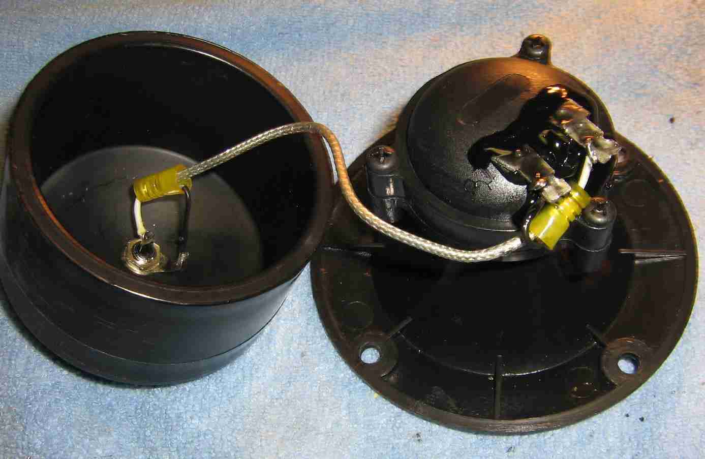
Add a RCA phono jack to the back of the 2-inch cap.
Use shielded wire to connect the RCA jack to the piezo horn tweeter.
A few dabs of liquid electrical tape on the terminals will secure the connection.
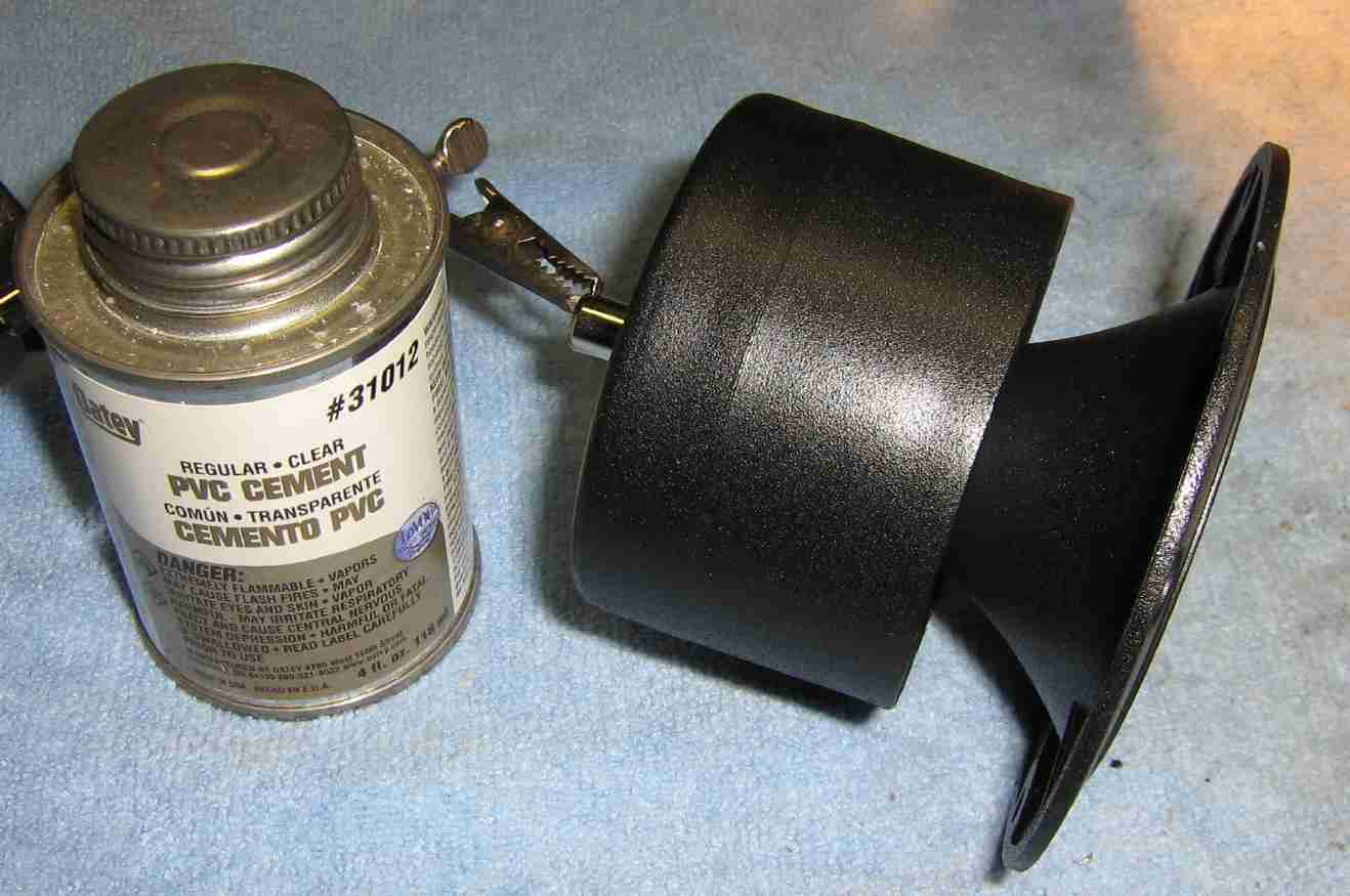
Slide the piezo horn tweeter into the 2-inch cap and secure using PVC cement.
This will then connect to the J2 Input on the piezo contact microphone amplifier circuit.
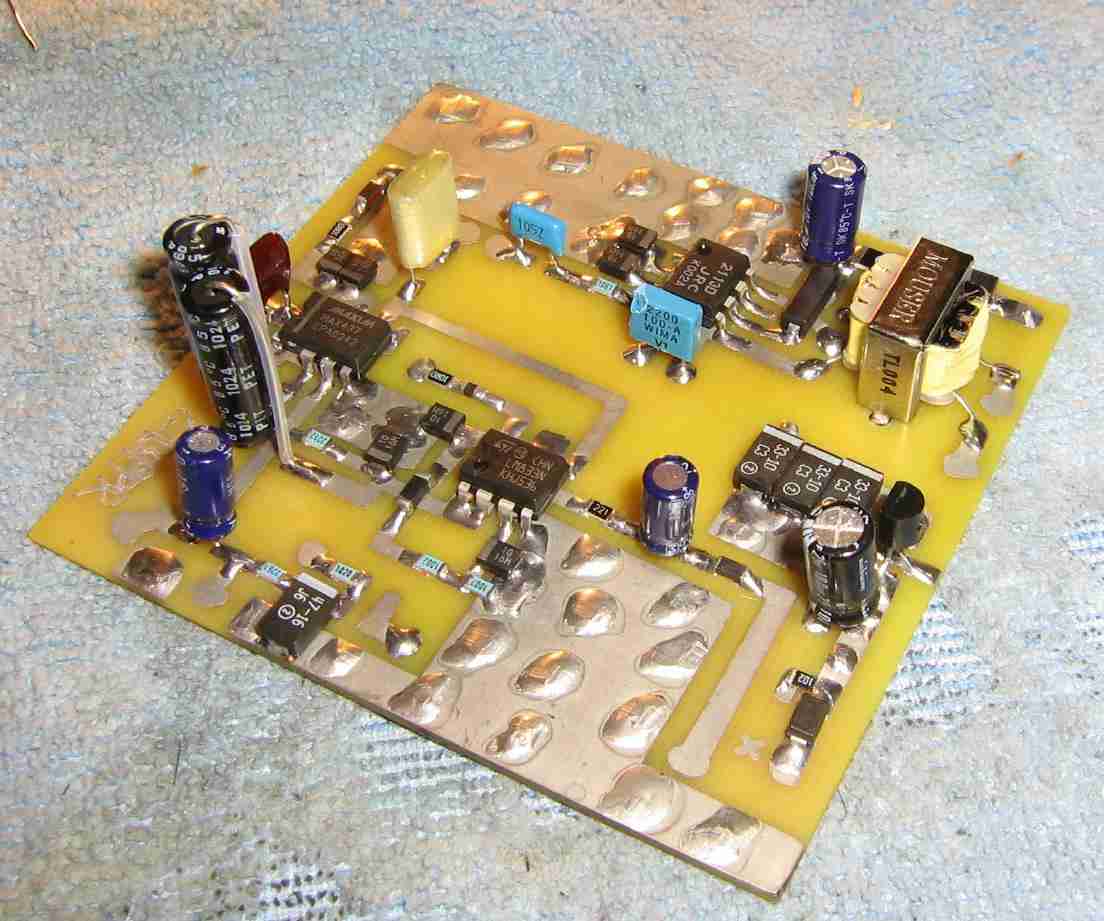
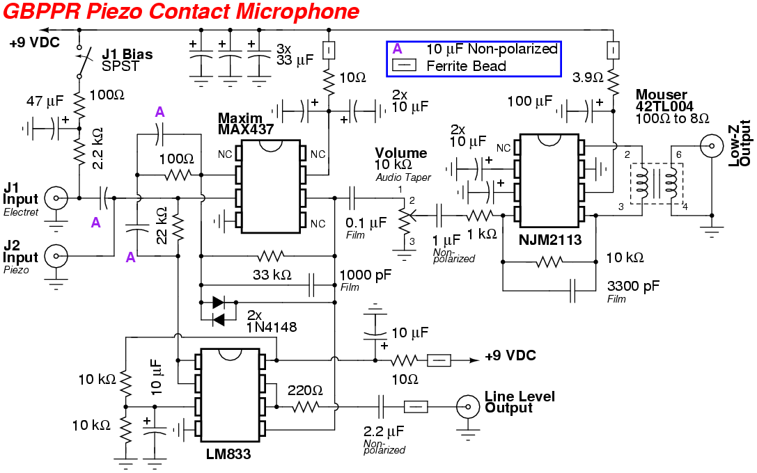
Overview of the GBPPR Piezo Contact Microphone circuit.
The Maxium MAX437 op-amp is on the middle-left. The MAX437's feedback network is configured to roll-off anything below 160 Hz and above 4800 Hz.
One of the op-amps in the LM833 is used as an active split-rail bias for added stability, the other is used as a buffer for the Line Level output.
The JRC NJM2113 low-noise audio power amplifier and Mouser 42TL004 isolation transformer are on the upper-right.
Maxim doesn't make the MAX437 op-amp anymore, but you can find them from time-to-time on eBay. The OP37 is still being manufactured by several sources and is a drop-in replacement.
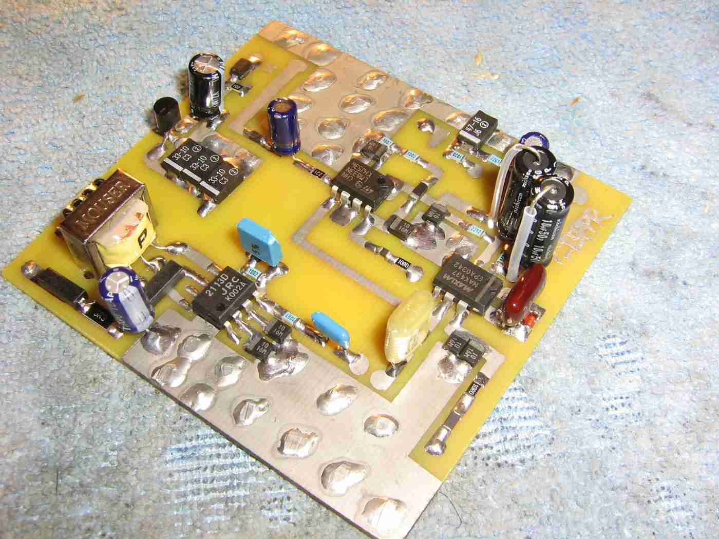
Alternate view.
The circuit has a DC bias select switch (J1 Bias) in case an electret microphone is used. The DC bias is only applied to the 1/8-inch J1 Input jack. The J2 Input jack is DC coupled directly to the MAX437 op-amp for maximum low-frequency response.
A standard electret microphone element can be used as a contact microphone by removing the felt pad on the front of the micrphone and then placing it against the item to be monitored.
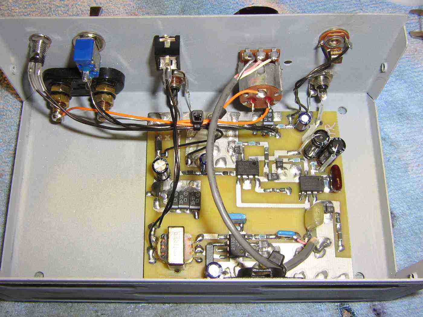
Mounting the circuit board inside an old printer switch case.
+12 VDC power input is via the banana jacks on the left.
The Lo-Z Output (headphone) and Line Level output jacks are next to the banana jacks.
The 10 kohm volume potentiometer with an integrated power switch is next to that.
The contact microphone input jacks are on the right. The top jack is a standard 1/8-inch jack and the bottom one is a RCA phono jack.
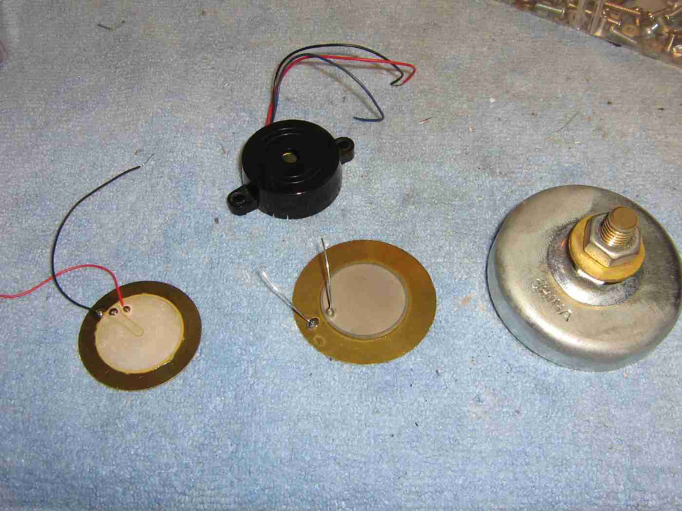
Example of some piezoelectric elements from old buzzers.
These will be adapted into makeshift contact microphones.
A mini-magnetic ground block will be used to mount one of the piezoelectric elements to make a handy magnetic-mount contact microphone for safe cracking.
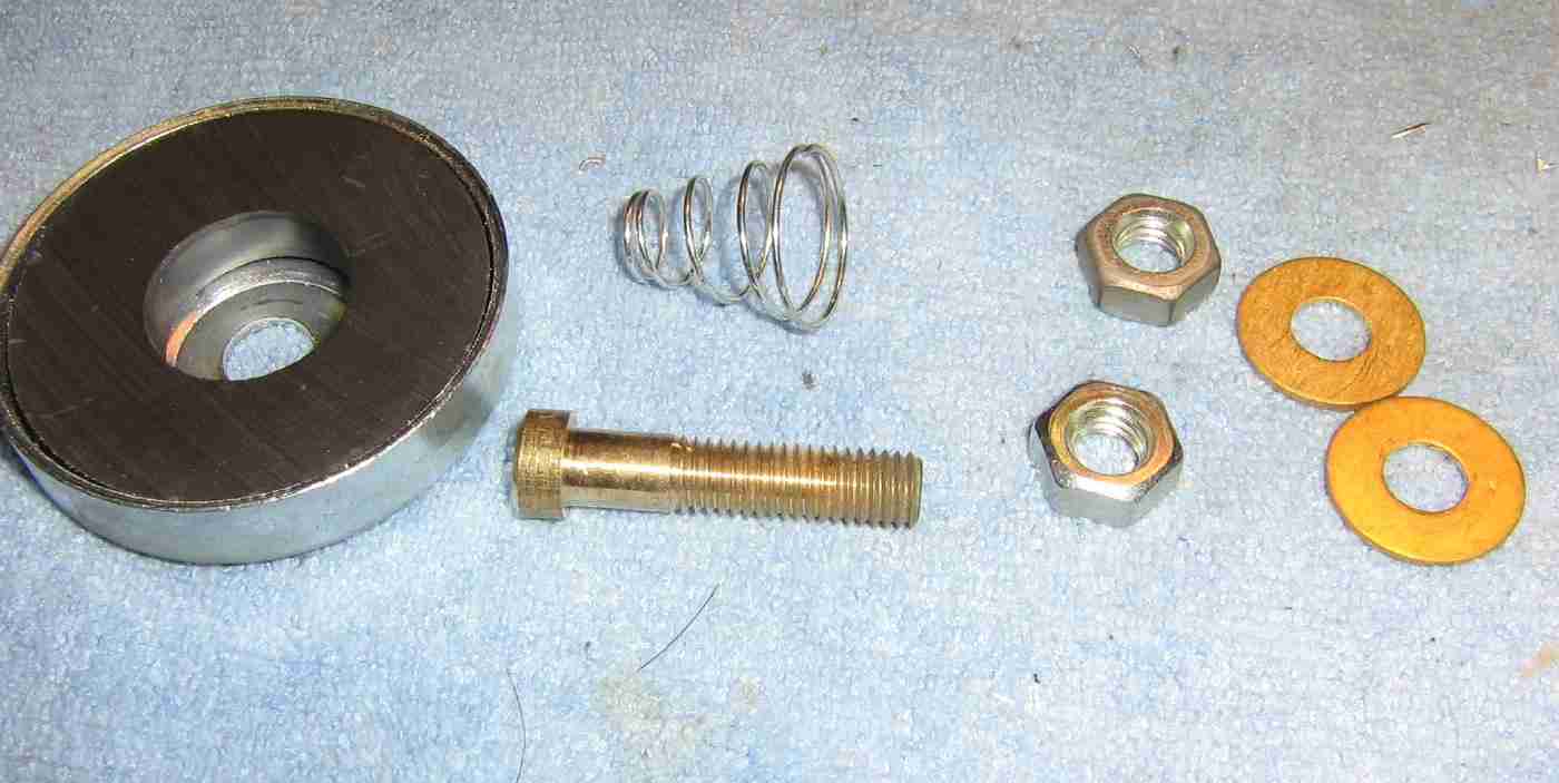
Overview showing the pieces of the magnetic ground block including the main spring-assisted brass stud.
You should polish the "head" of the brass stud using some 1000 grit sandpaper.
You may want to purchase several magnetic ground block so you have spare components to experiment with.
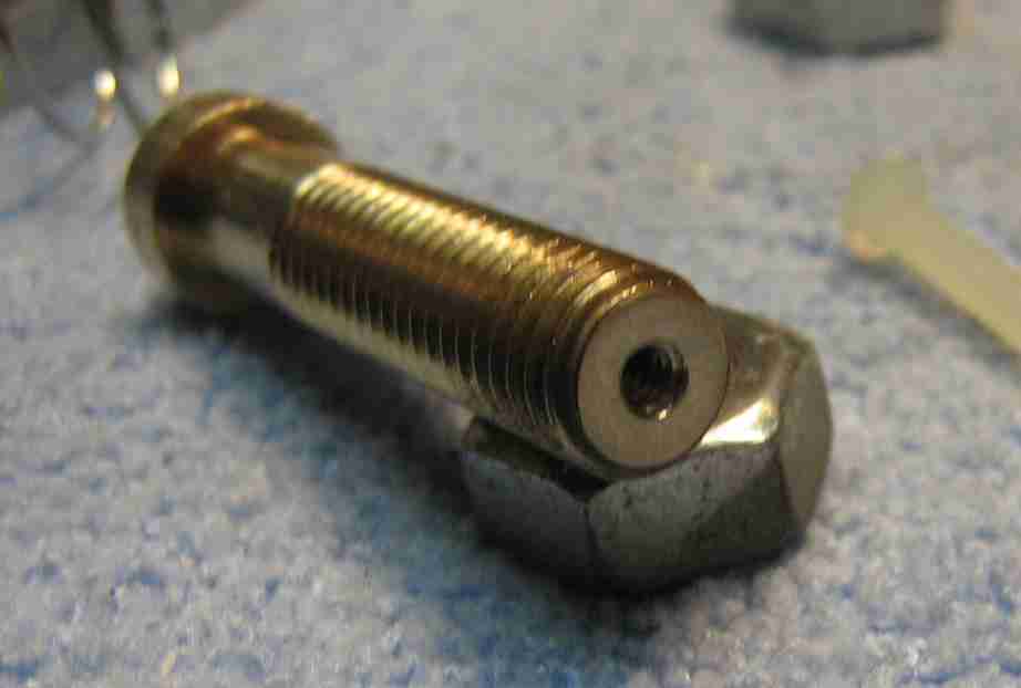
Very carefully drill and tap a #4-40 screw hole in the center of the "threaded end" of the magnetic ground block's brass stud.
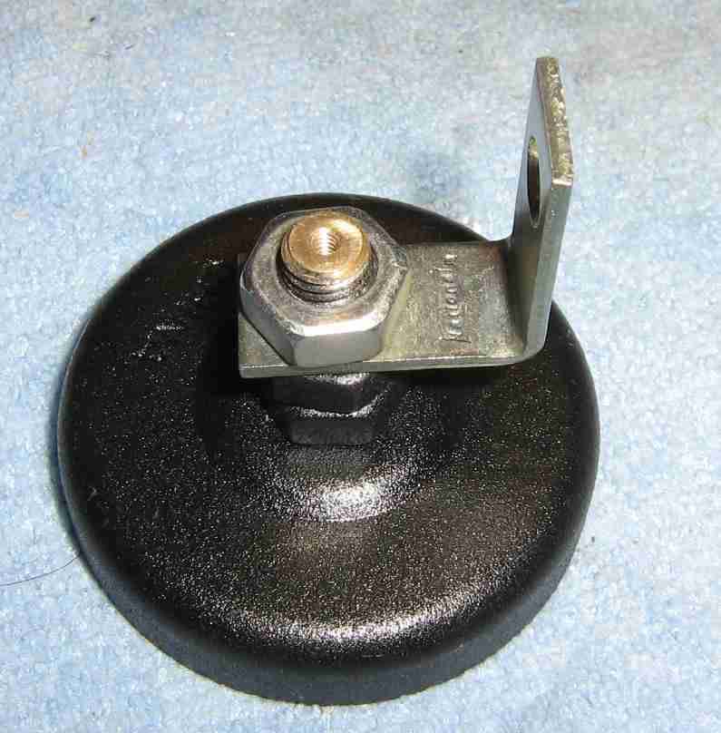
Mount a small L-bracket to the threaded brass stud of the magnetic ground block, as shown above.
This will be used to hold a RCA phono jack for the output of the contact microphone.
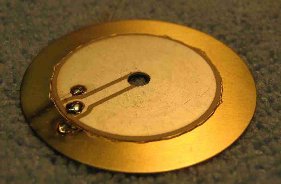
Drill or punch a 1/8-inch hole in the center of a piezoelectric buzzer element.
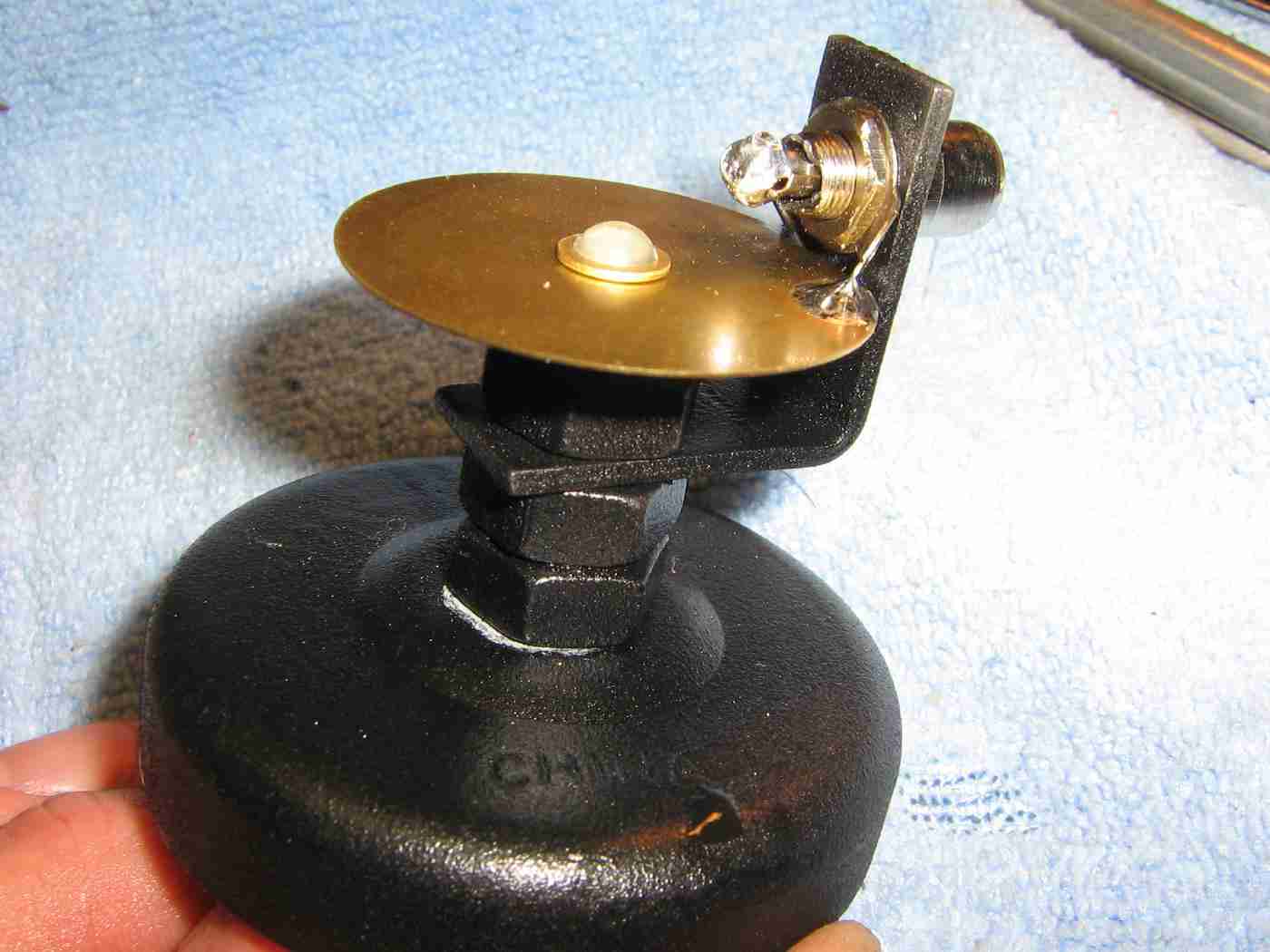
Completed magnetic-mount contact microphone.
Mount the piezoelectric buzzer element to the top of the magnetic ground block's brass stud using two #4 nylon isolation washers (on the top and bottom of the element) and a #4 nylon bolt.
The #4 nylon hardware will electrically isolate the piezoelectric element from the brass stud.
Mount a RCA phono jack in the hole in the L-bracket.
The ground tab on the RCA jack goes to the exposed brass outer-ring on the piezoelectric element.
The center tab on the RCA jack goes to little solder blob on the piezoelectric element material itself.
Any vibrations are now passed via the brass stud directly to the piezoelectric element.
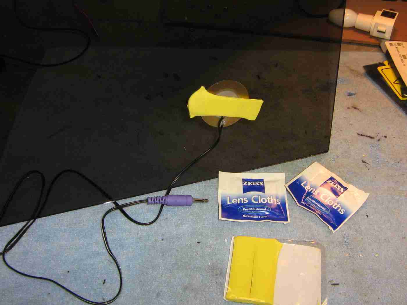
For "through a window" applications, attach the piezoelectric element directly to the target window using Elmer's Poster Tack reusable putty adhesive.
Prepare the window surface with a lens cloth.