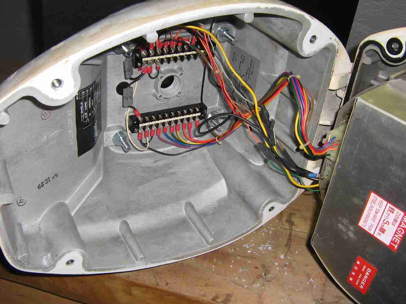
Furuno Model FR-360 Mark II scanner unit wiring as I receive it.
Note several wires not properly connected, so use these initial pictures for reference only!
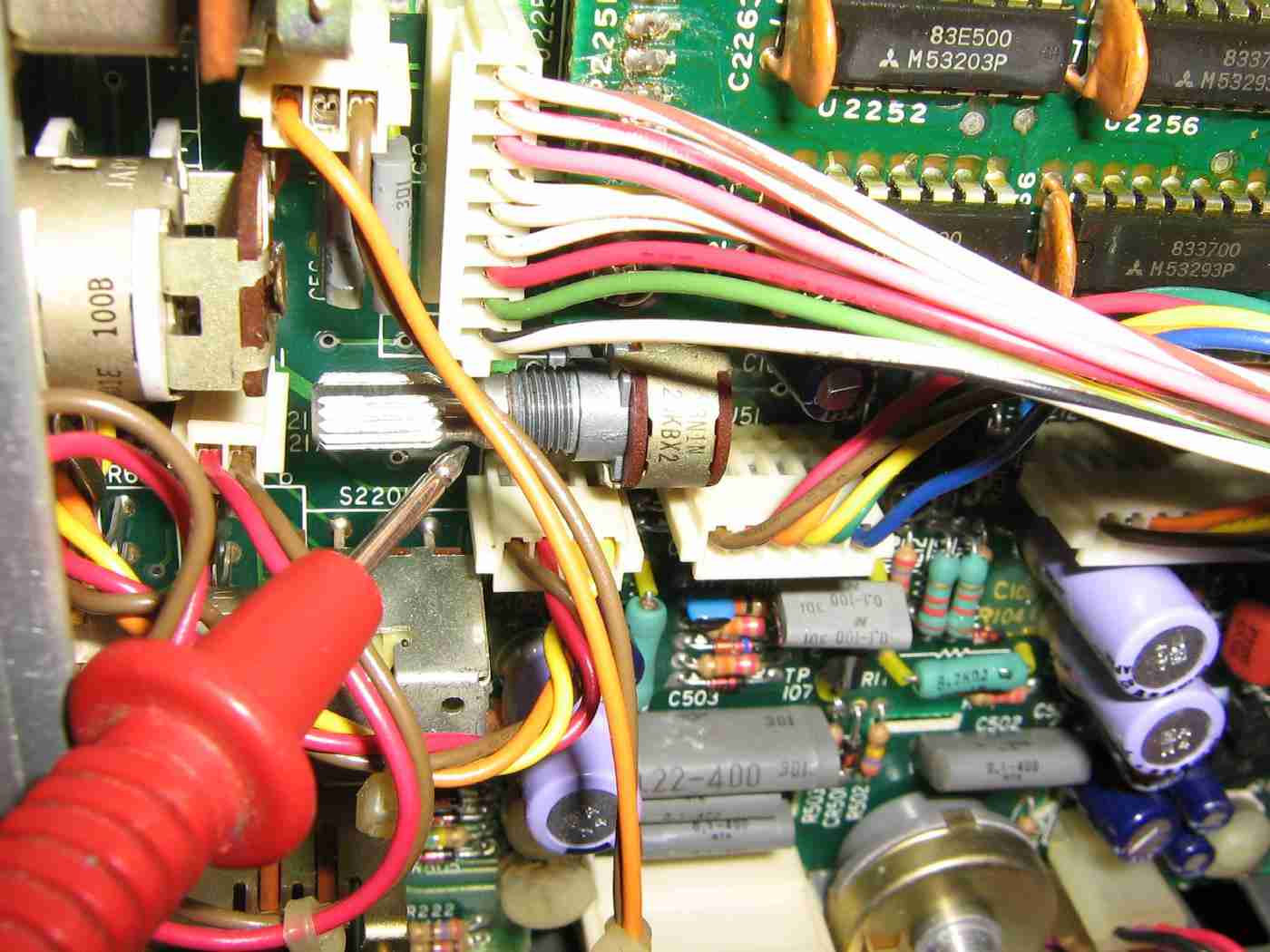
The system shares a common ground with the signal cable's shield. There are a few ground "jumper" wires, which makes the cabling look messy.
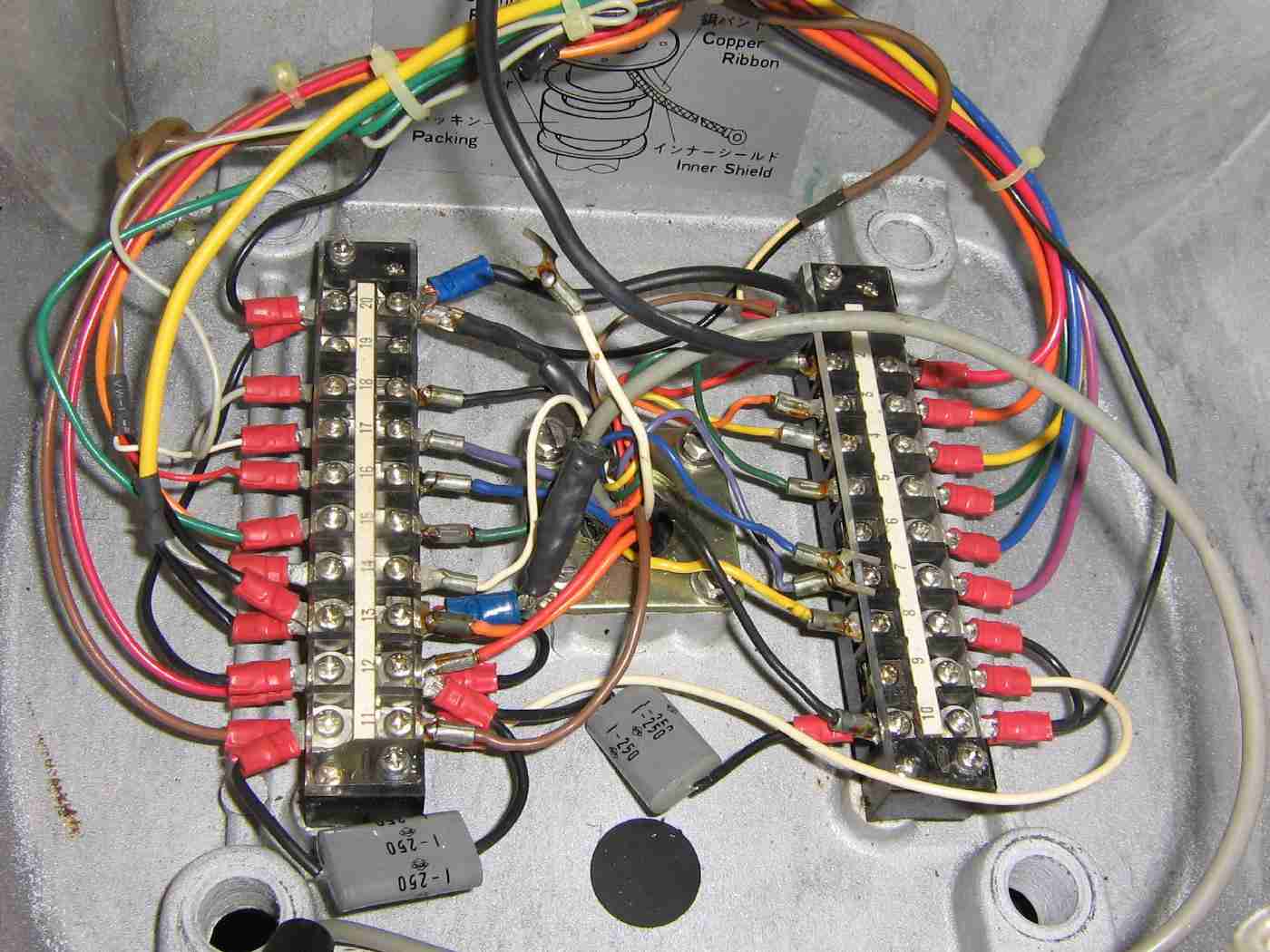
Pin 1 on the terminal block is on the upper-right. Pin 10 is on the lower-right. Pin 11 is on the lower-left. Pin 20 is on the upper-left. Pin 19 was unused.
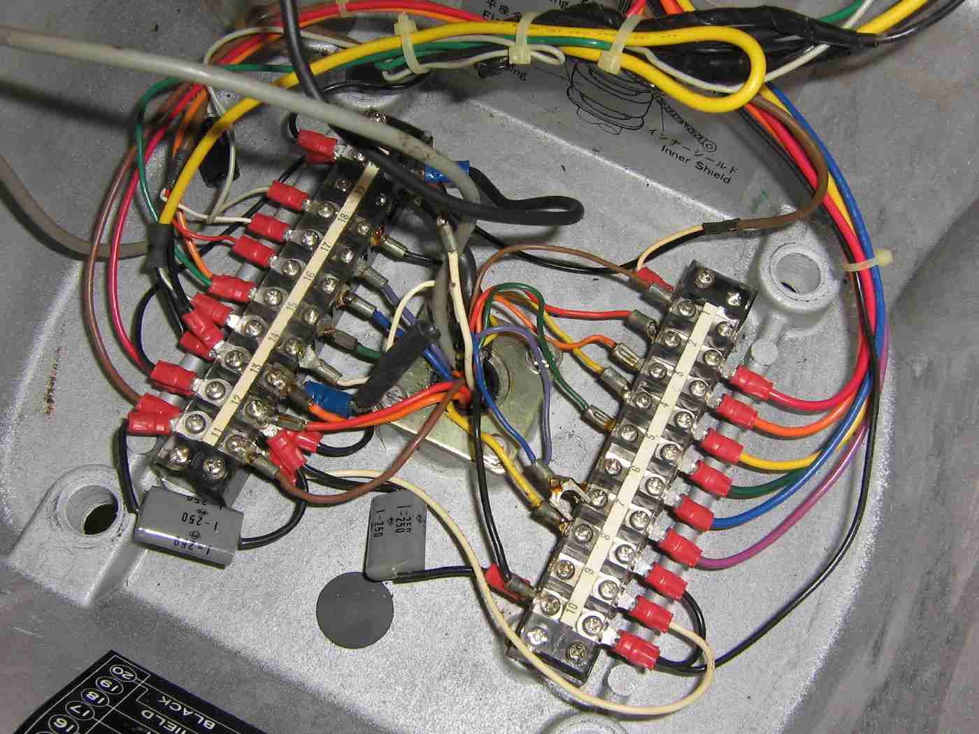
Alternate view.
There are two 1 µF/250V non-polarized capacitors to ground (those gray things) across the magnetron's heater (filament) connections.
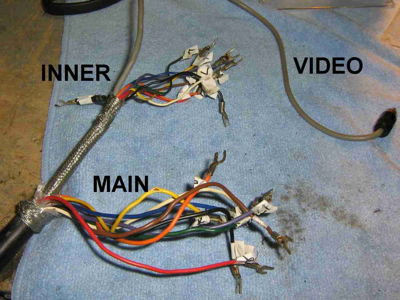
The signal cable come up through the bottom of the scanner unit. The signal cable contains two wire bundles and a coaxial cable with a RCA plug for the video signal. The two cable bundles share a common ground via the shield.
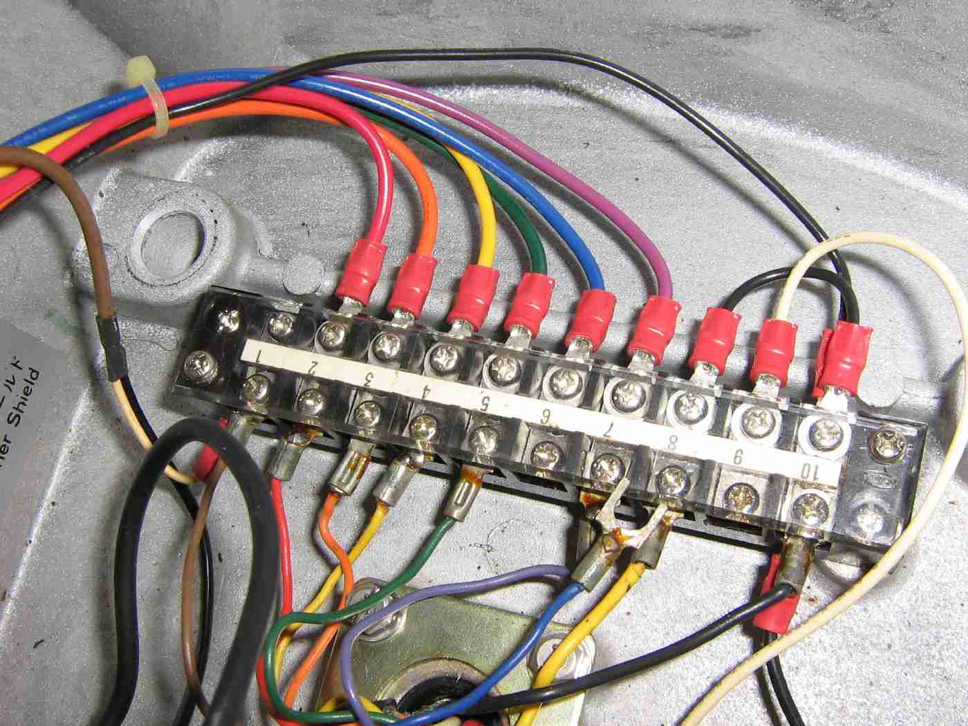
Terminal block pins 1 through 10.
Incoming signals from the signal cable are on the bottom connections of the terminal block.
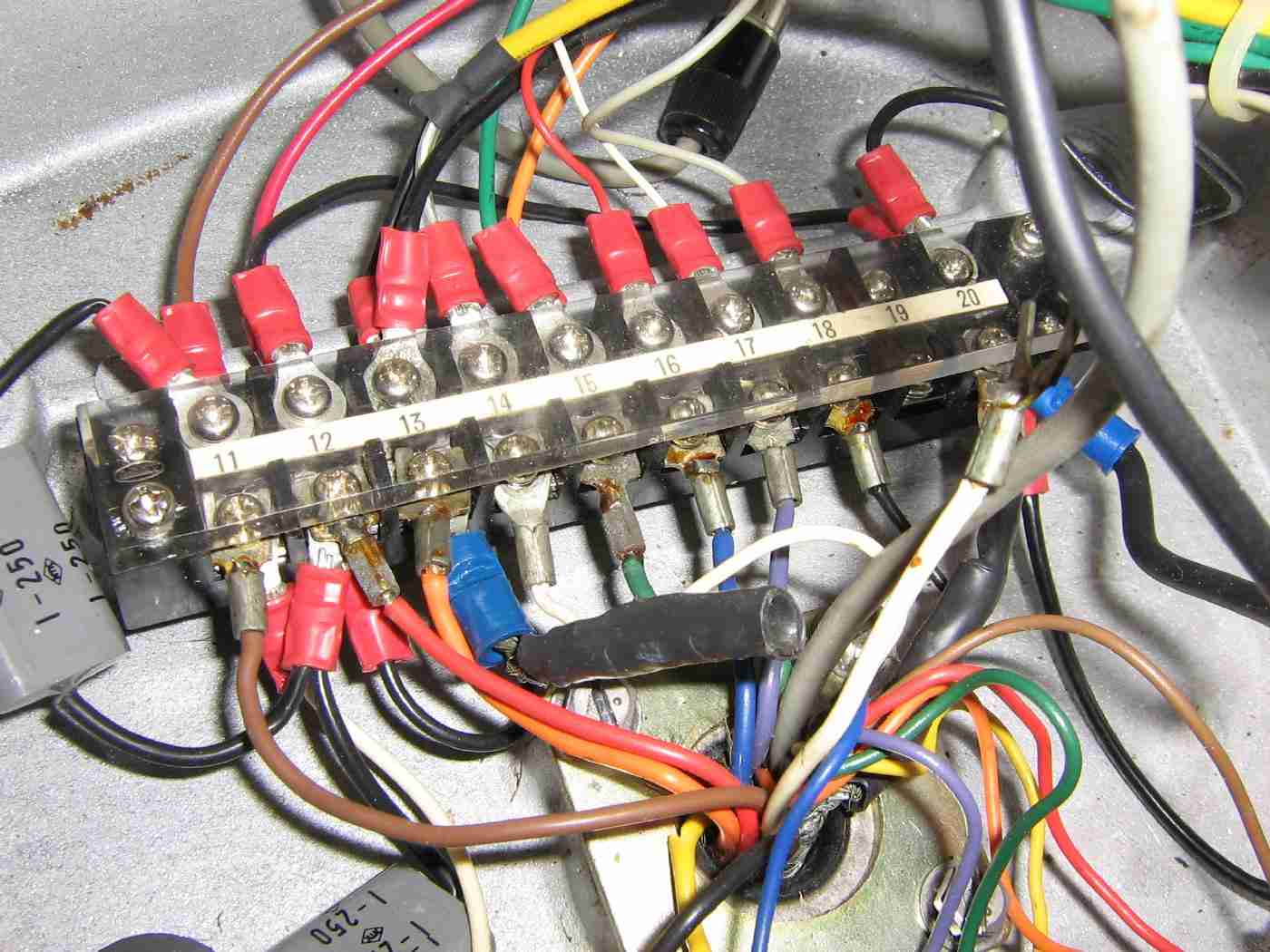
Terminal block pins 11 through 20.
Pins 12, 13, and 20 are a common ground.
Incoming signals from the signal cable are on the bottom connections of the terminal block.
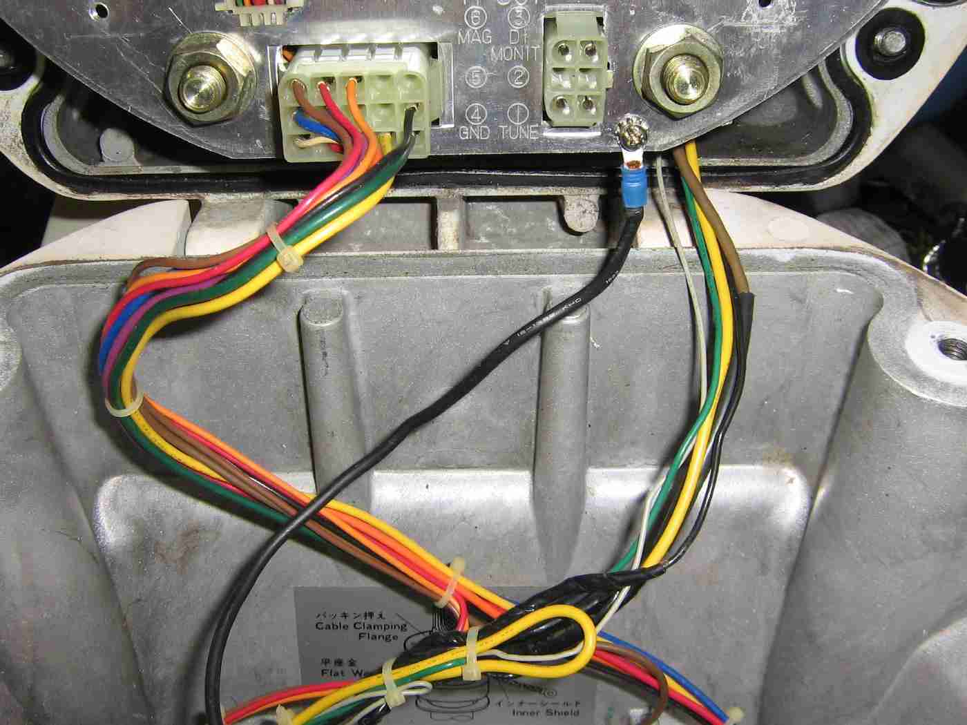
Wire connections to the cover of the scanner unit.
The large black wire is a common ground which connects to pin 20 on the terminal block.
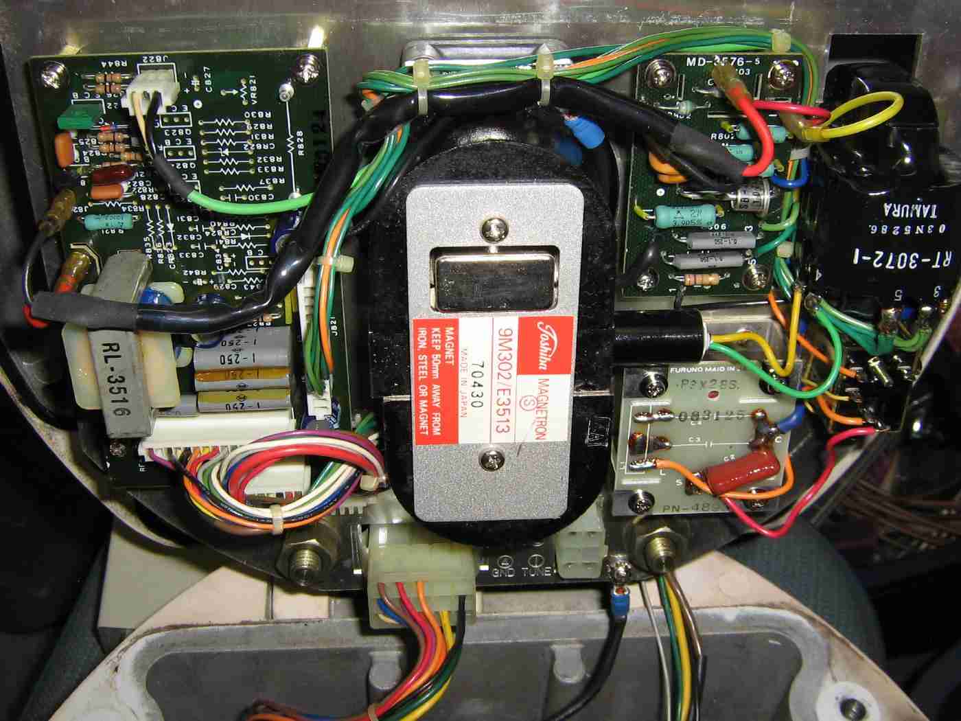
View of the Toshiba 9M302/E3513 X-band pulse magnetron.
This magnetron's output frequency is around 9.41 GHz. It uses a standard WR-90 flange and is connected to port 1 on the output circulator.
The Pulse-Forming Network (PFN) is on circuit board to the lower-right. The relay switches between long and short pulses.
The pulse transformer is off to the far-right, labeled RT-3072-1. This converts the +300 VDC on the PFN into an approximate -3.7 kV pulse for the magnetron.
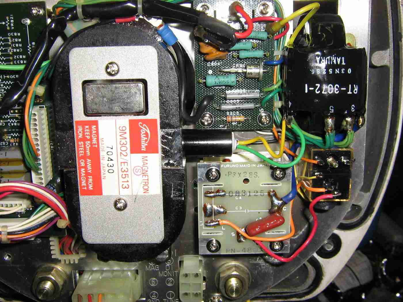
Closeup picture of the pulse magnetron, pulse-forming network, and the pulse transformer.
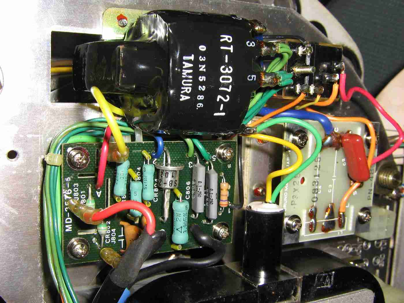
Alternate view of the pulse-forming network and the pulse transformer.
The GREEN wire on the magnetron is for the heater (filament) and the YELLOW wire is heater and cathode.
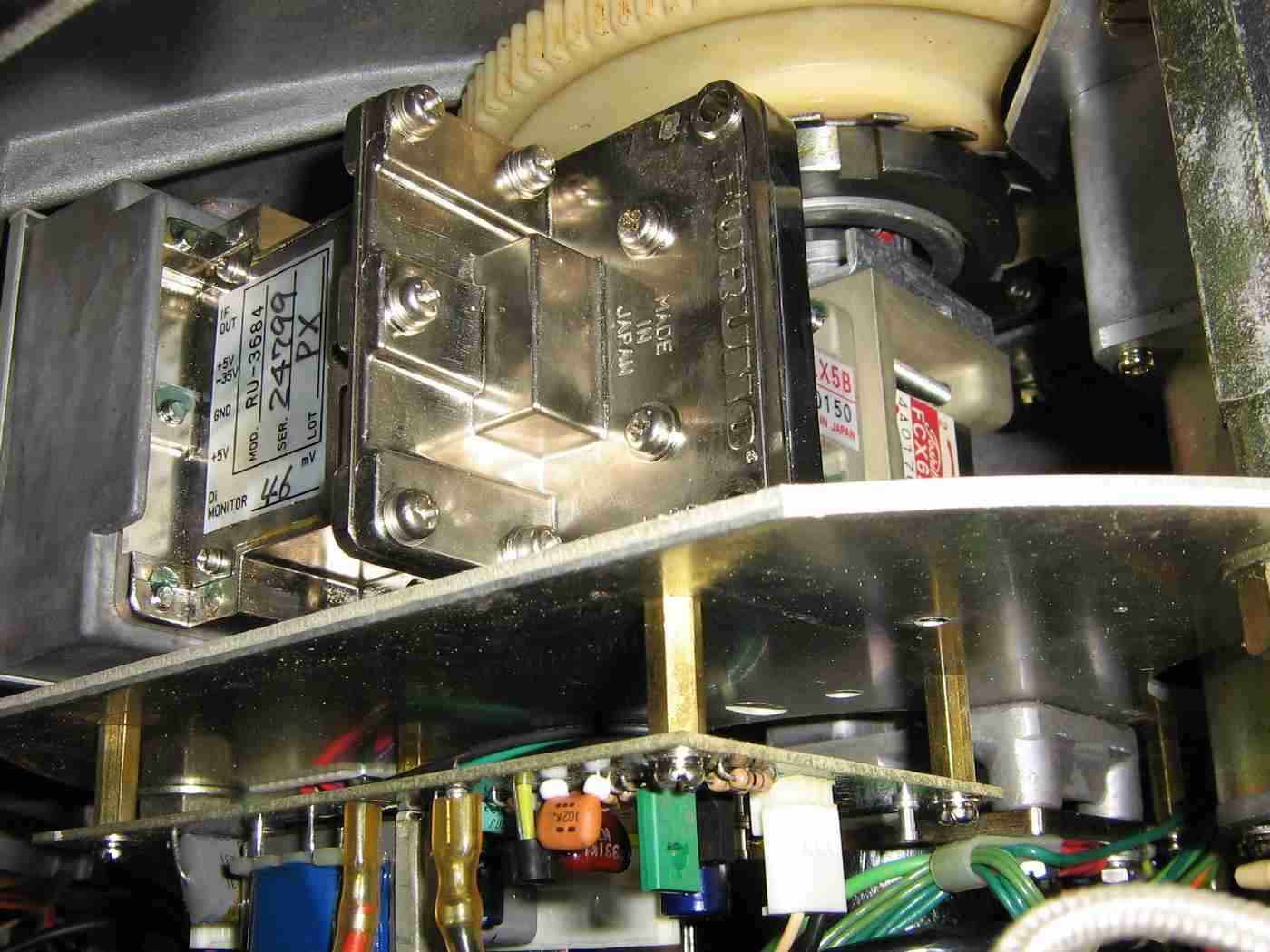
View of the local oscillator and mixer assembly, labeled RU-3684.
I don't have a schematic for this module, but it contains a variable local oscillator to produce a final IF frequency of around 40 MHz. This module has a +5 VDC to +35 VDC tuning voltage to compensate for slight frequency changes to the magnetron as it ages.
This local oscillator module has a "monitor" output, but I'm not sure what that is used for.
A passive diode limiter, labeled S-LX5B(S), precedes this module to protect it from being damaged by the high power magnetron pulses which get past the output circulator.
The output circulator is labeled FCX-62. Its port 3 goes to the receive circuits and port 2 is connected to the main antenna output.
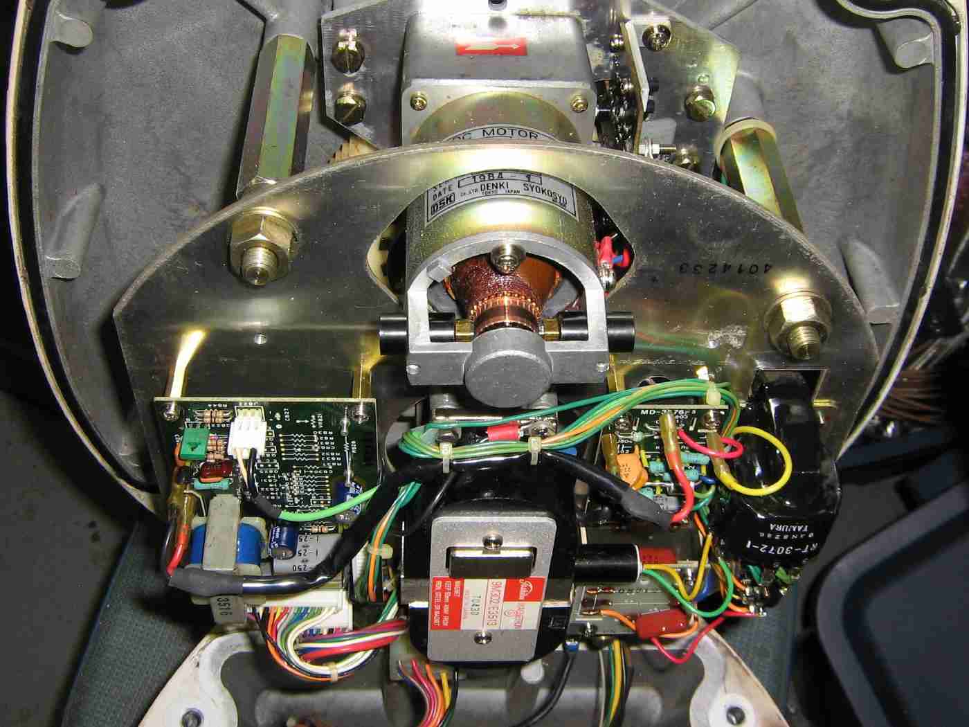
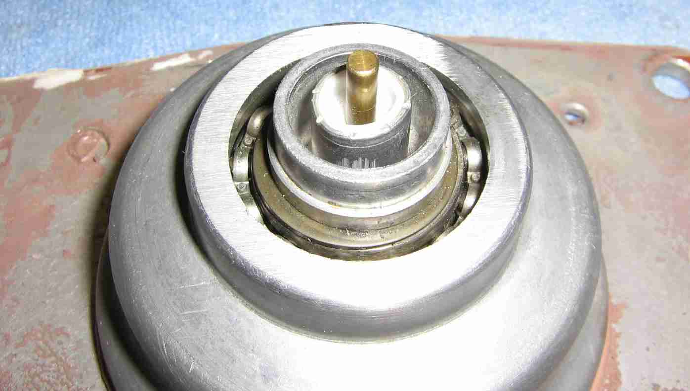
Overview of the antenna mount rotation motor.
This motor operates off +/- 12 VDC (a total of 24 volts) and spins at around 24 rpm.
An optocoupler provides a bearing pulse signal to step the display rotation motor and a magnetic reed switch provides the heading flash signal.
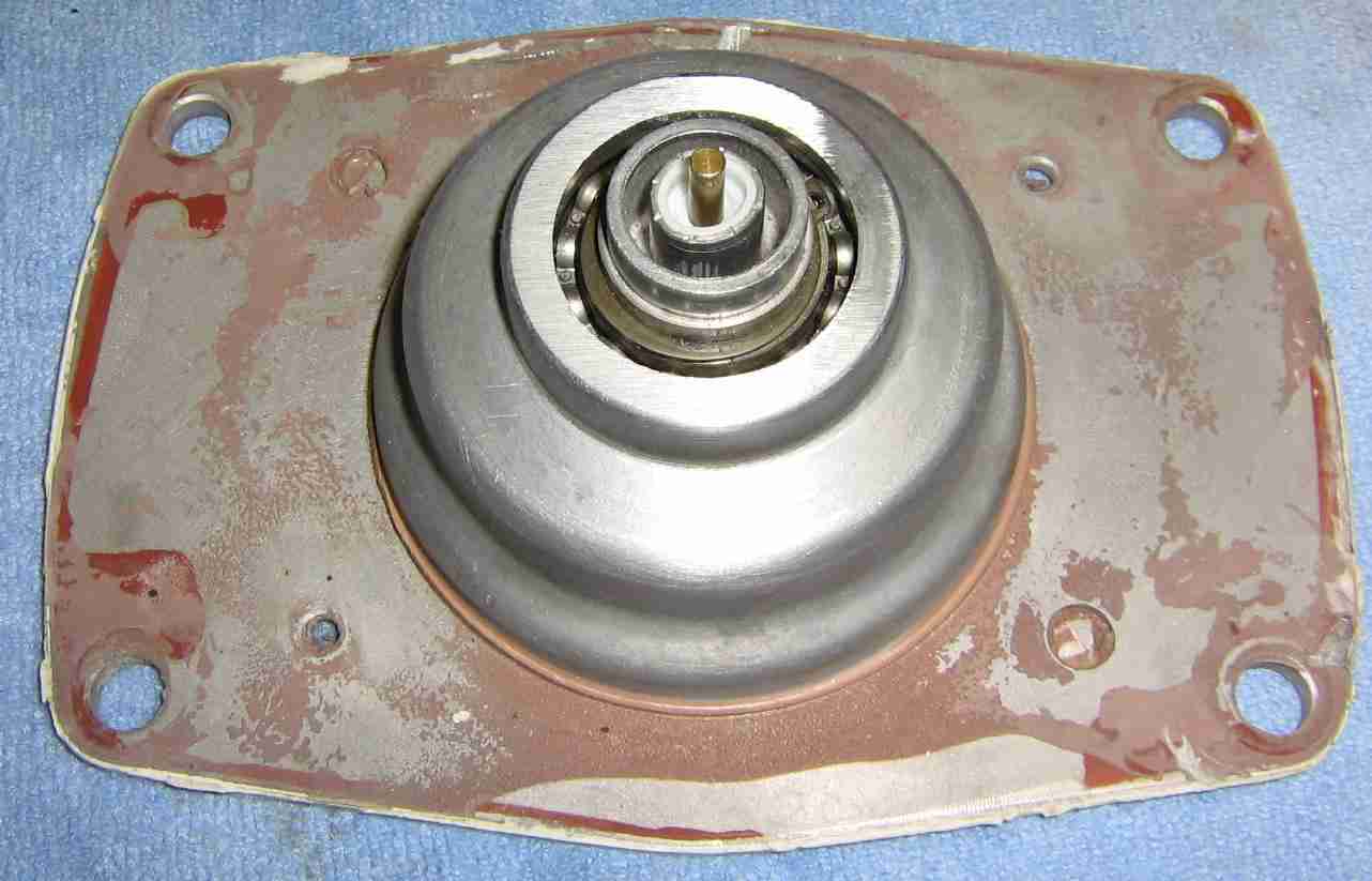
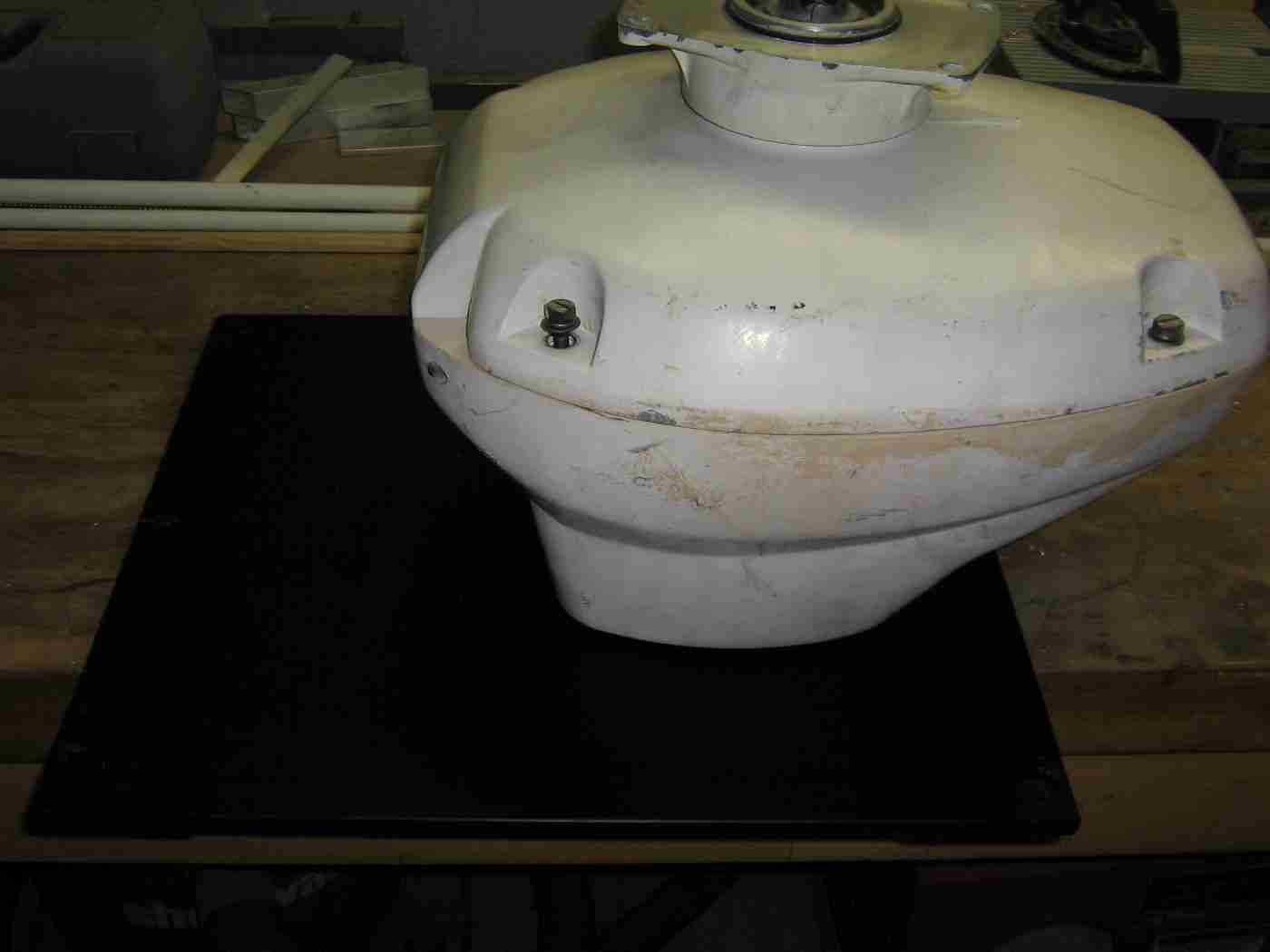
Antenna mounting plate from the stock Furuno antenna system.
The brass probe is a 1/4 wavelength antenna and will stay stationary as the mounting plate rotates around it.
The antenna as I received it was smashed, so I ripped it apart before taking a picture of it, but this is the only part you'll need from the stock antenna.
Closeup of the brass antenna probe.
The tube surrounding this probe is about 0.5-inches in diameter.
The brass probe is essentially a center conductor in a piece of hardline coax.
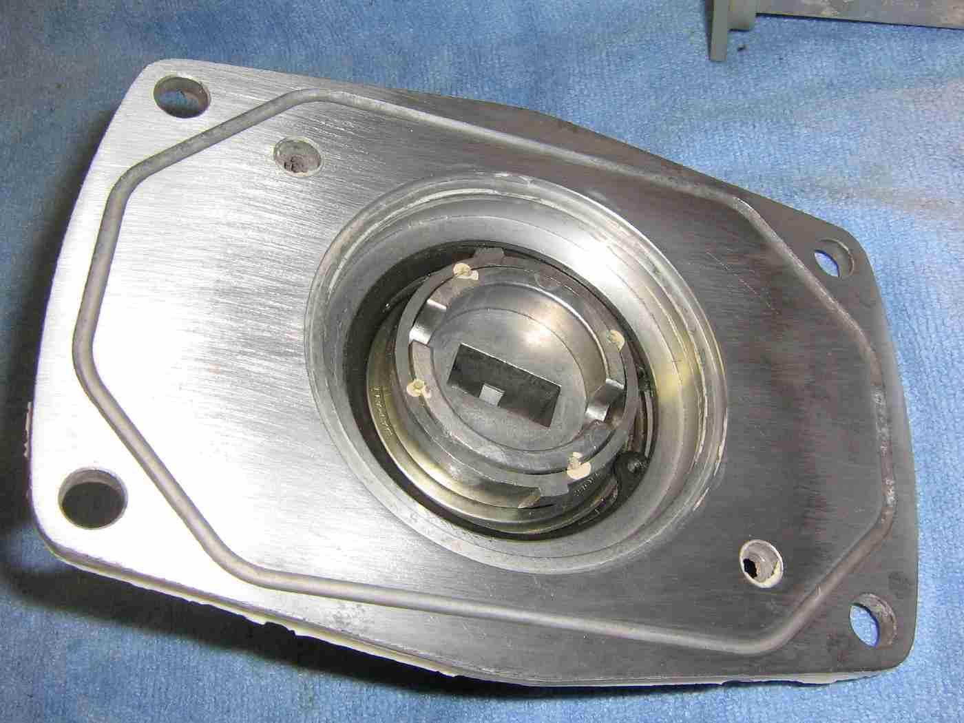
Bottom of the rotating antenna plate.
The WR-90 flanges interlock and will stay stationary while the plate rotates around it.
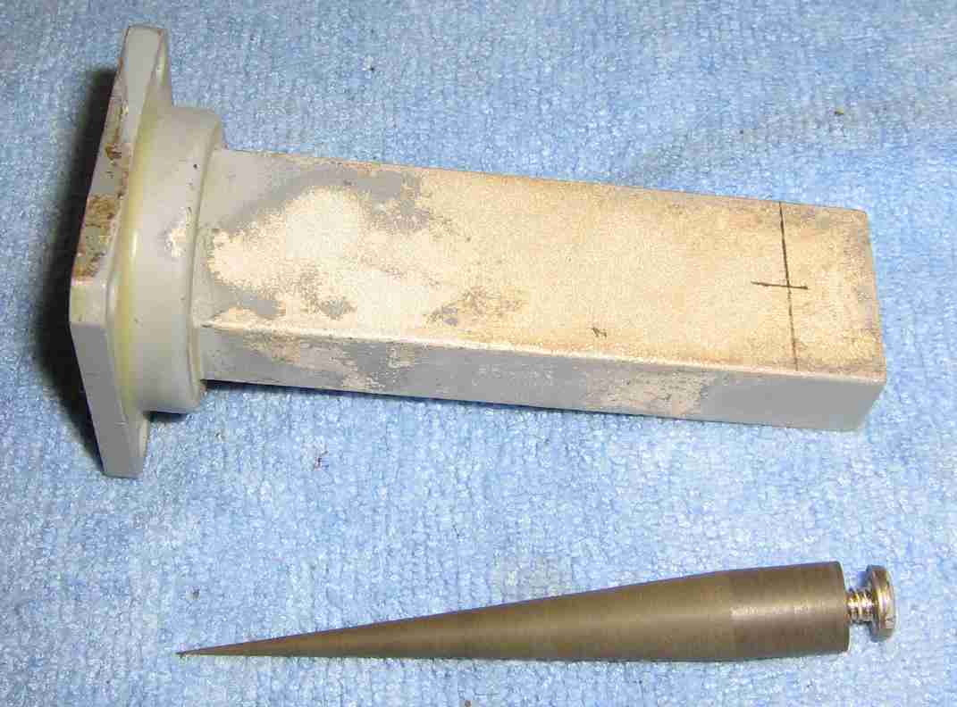
A surplus Waveline Type 564 2 watt, 50 ohm termination load with a WR-90 flange.
We'll use this to couple the output from the 1/4 wavelength brass probe antenna into something more usable.
The ferrite load will need to be removed.
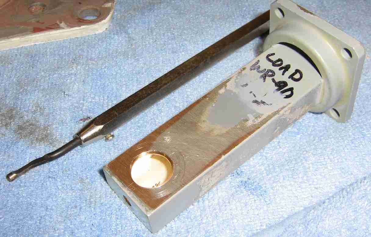
Drilling the coupling hole for the 1/4 wavelength brass probe.
Drill a 1/2-inch diameter hole 11 millimeters from the closed end of the waveguide.
Because this waveguide will need to rotate around the 1/4 wavelength brass probe, and the little flange which surrounds it, slightly widen the drilled hole using a deburring tool.
You want the waveguide to spin freely around that round flange but still be fairly RF tight.

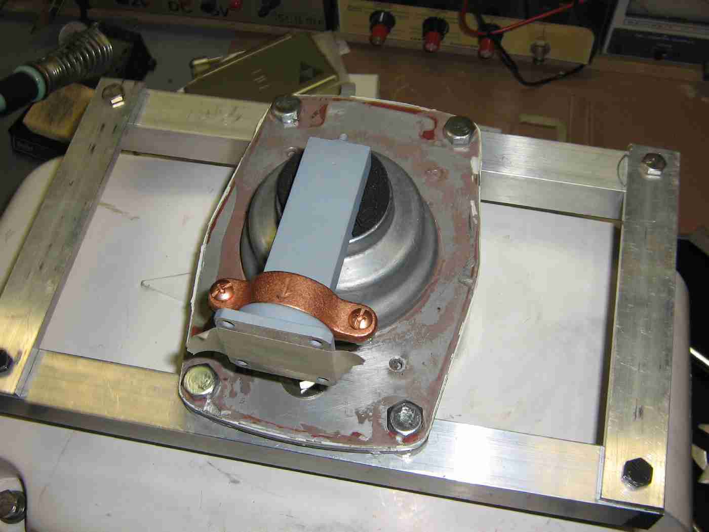
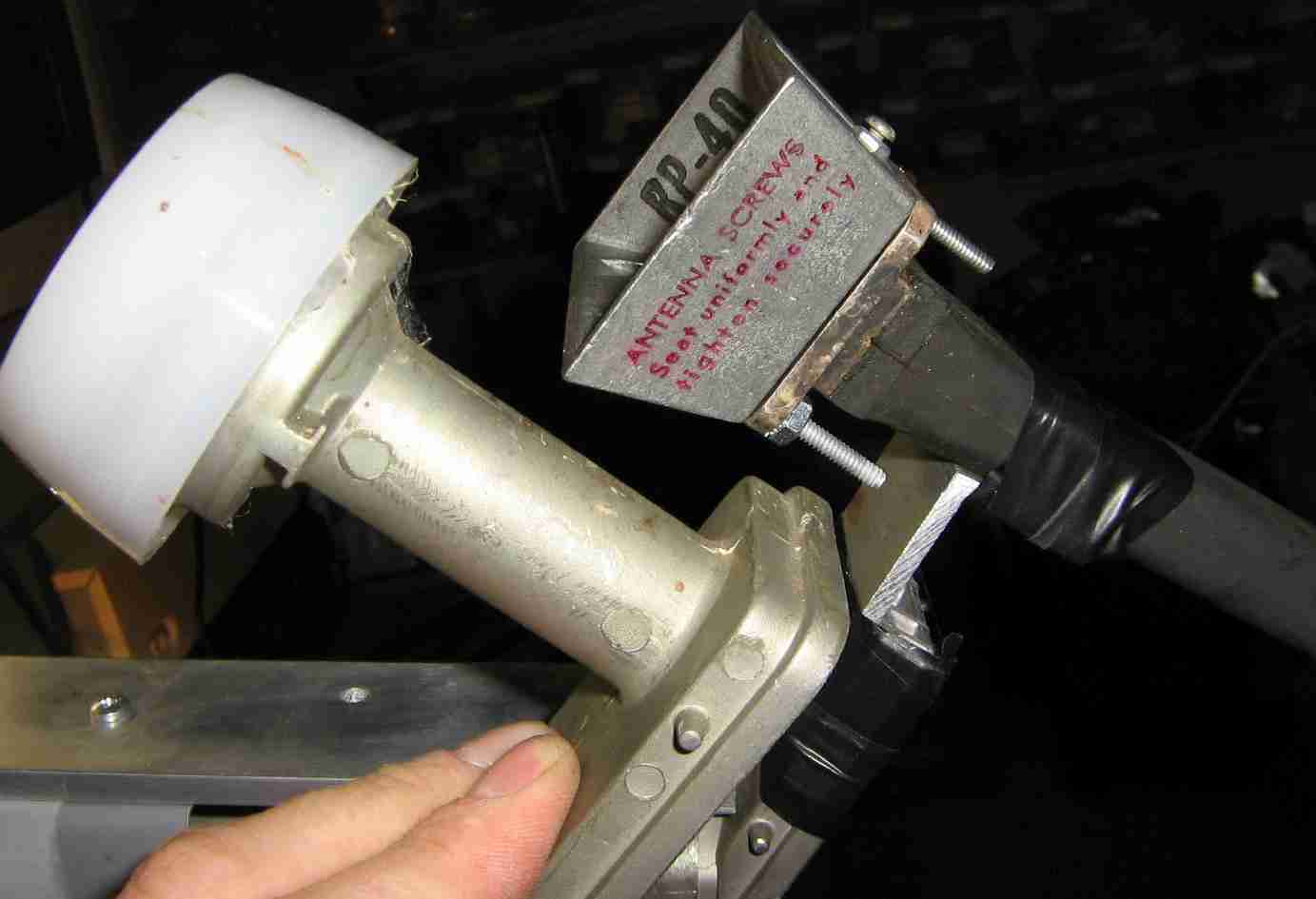
Example of how this new waveguide piece should fit around the 1/4 wavelength brass probe antenna.
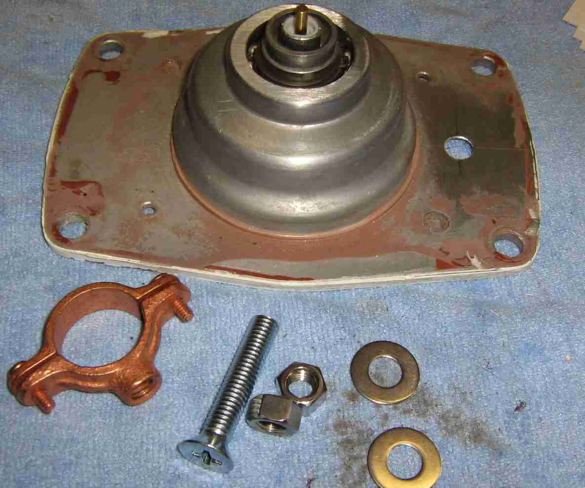
To secure the waveguide to the rotating plate, we'll use a 1-inch copper pipe hanger clamp and some 3/8"-16 hardware.
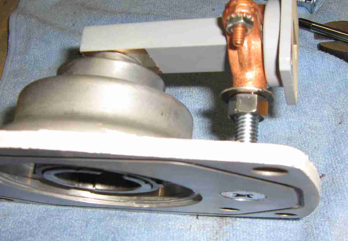
Secure the waveguide as shown using the 1-inch copper pipe hanger clamp. Be sure it is level.
The hole for the main 3/8"-16 bolt should be countersunk.
I added two extra #10-24 Kep nuts on the 1-inch copper pipe clamp. This is a fairly critical connection, and will be under a bit of stress, so take your time and do a good job. Secure the 3/8"-16 hardware with a few drops of Loctite.
Also add a bit of grease along the area where the waveguide rotates around the probe hardware.
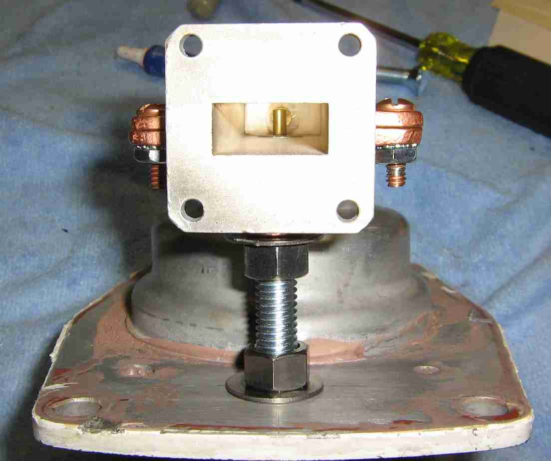
Complete view showing the 1/4 wavelength brass probe antenna inside the new waveguide.
I added a #6-32 brass screw to cover the hole in the waveguide originally used to mount the ferrite load.
The output RF polarization will be vertical.
I mounted the scanner unit of the radar to large piece of scrap plastic.
This makes working on the radar much easier when then hinged cover is opened up.
Internal view of the scanner unit showing the correct internal wiring..
To mount the new parabolic dish antenna, make a simple aluminum frame using some 1-inch square tube and bar stock.
The two square tubes are 12-inches in length and are attached to the rotating plate with 3/8"-16 hardware.
Some black foam washers were added to help cover up the bearing assembly in the rotating plate.
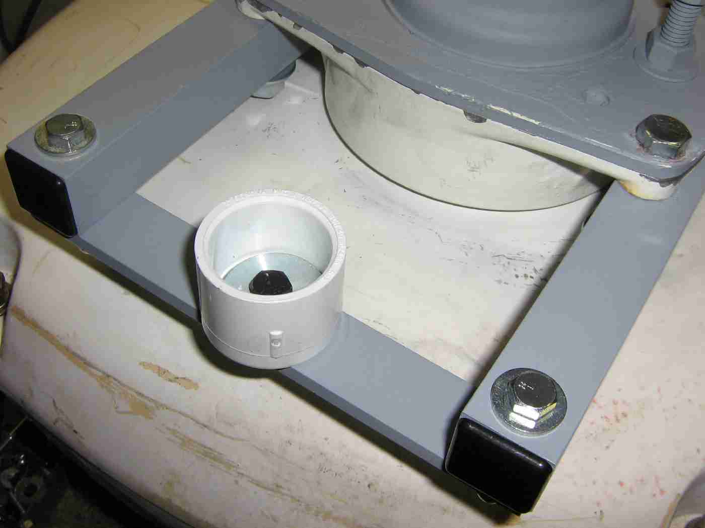
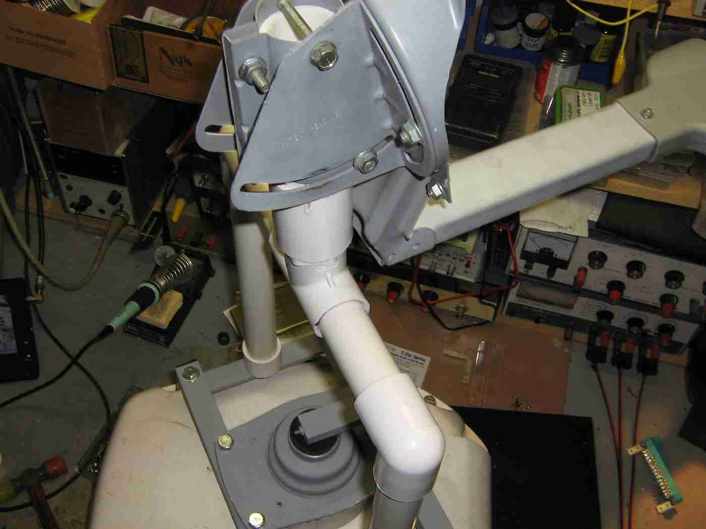
To save weight, the support structure for the new parabolic dish antenna will be made from 1-inch diameter PVC pipe.
Bolt two 1-inch PVC end caps to the center of the support bars as shown above. Secure them using a fender washer inside the end cap and some 1/4"-20 hardware.
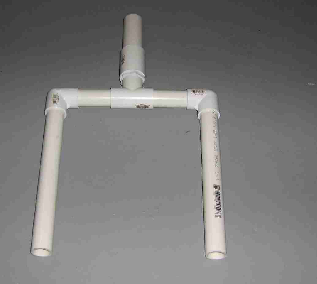
Support structure for the new parabolic dish antenna made from standard 1-inch diameter PVC pipe.
The two support legs on the sides are 12-inches long.
The two little horizontal legs are 4.25-inches long.
There is a 1-inch to 1.25-inch PVC adapter on the tee connector (and a short little vertical riser) as the DirecTV dish mounting hardware needs a 1.25-inch diameter mounting pipe for proper attachment.
Test setup showing the DirecTV dish mounting hardware attached to the short piece of 1.25-inch PVC pipe.
Try to keep the overall rotating structure weight as low as possible, but make sure the parabolic dish doesn't have any "wobble" as it rotates.
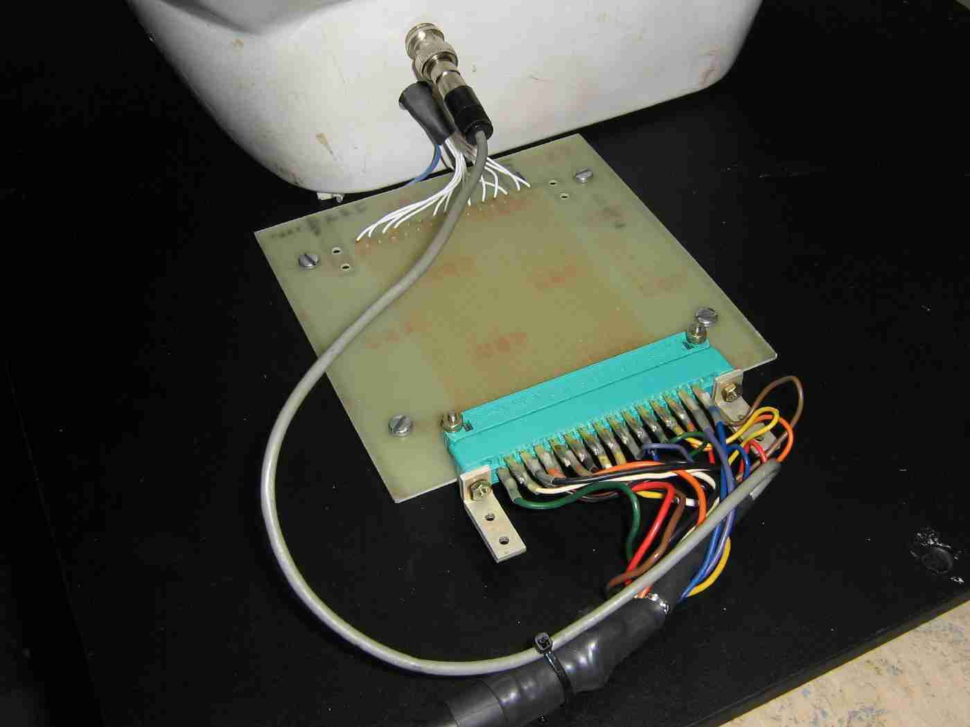
A handy option is to make a quick disconnect for the main signal cable.
This was made from a scrap piece of PC board which already had a nice edge connector.
A BNC jack was added for the video output signal from the scanner unit.
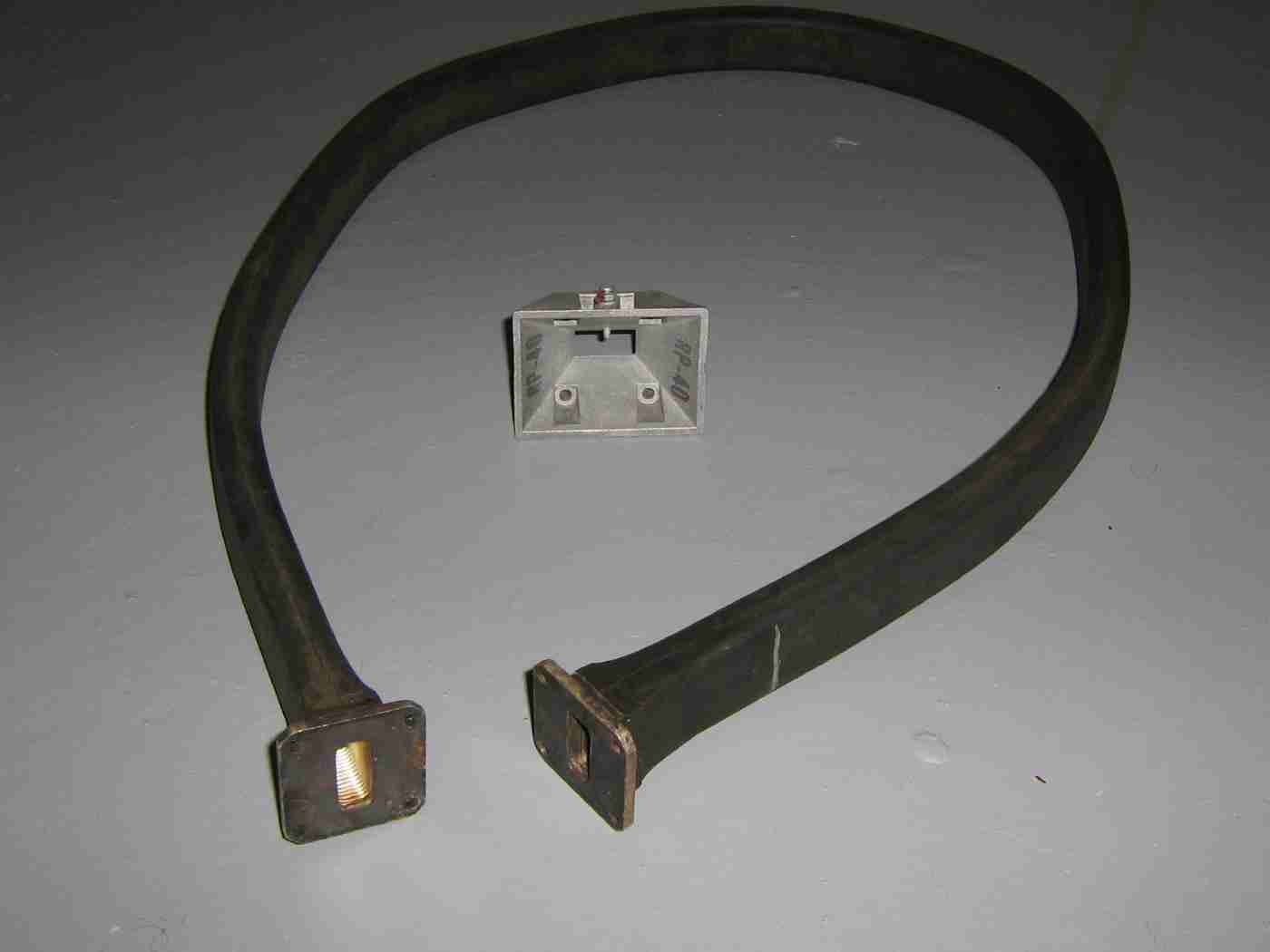
A four-foot piece of CG-179A/U flexible waveguide with WR-90 flanges connects the output from the new wavguide section we just made to the feed horn antenna.
The horn antenna is from the 10 GHz Gunnplexer used in a Solfan motion alarm.
The small f/D ratio (approximately 0.3) of DirecTV dishes means that the feed horn (and focal distance) can be quite critical, but use whatever you can find (or make) and then fiddle with it afterwards.
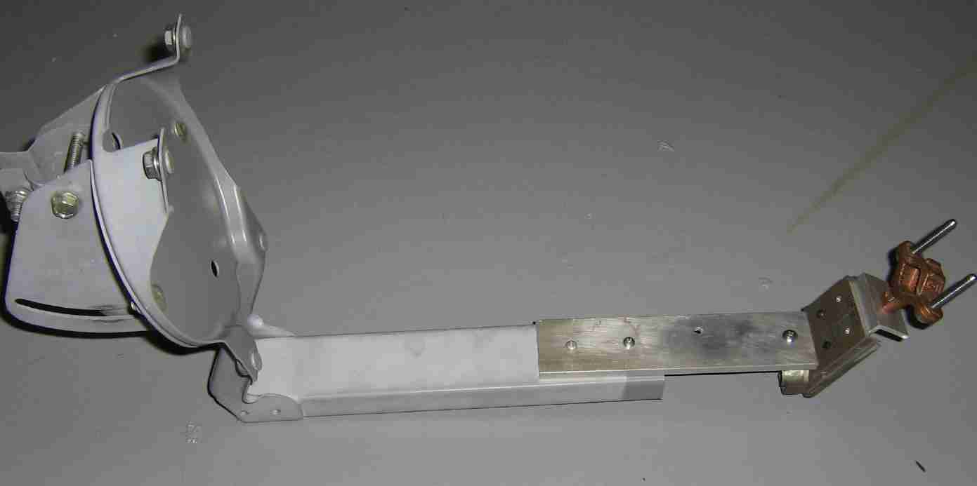
Constructing an usable feed horn mounting assembly.
This probably the hardest part of this project and can be quite critical.
We'll be using an old DirecTV low-noise block converter cut in half to provide the proper angle for the feed horn. An aluminum plate will need to be added to the dish's feed arm to extend the length a bit.
A piece of aluminum angle will provide the final mounting bracket for the flexible waveguide and feed horn at the proper focal point for the dish.
Try to eye everything up ahead of time so you know what it is all suppose to look like.
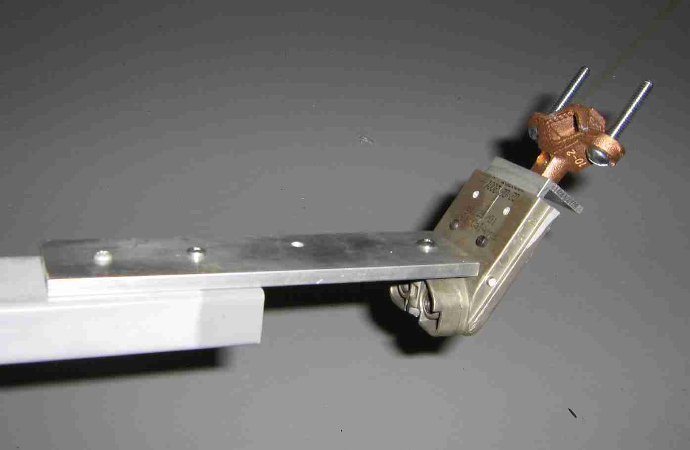
Overview of the modified DirecTV feed arm and feed horn mounting hardware.
The flexible waveguide is secured using a ground clamp attached to the little piece of aluminum angle stock.
The was all done empirically, but will work if you take your time and are careful during construction. The final focal point should be just inside the feed horn.
Alternate view with a better showing of the cut down DirecTV low-noise block converter.
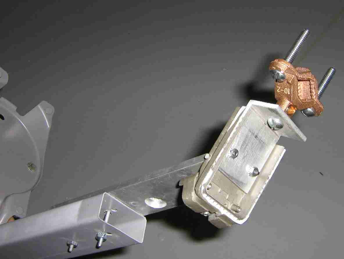
Rear view showing the aluminum angle stock and the ground clamp attachment.
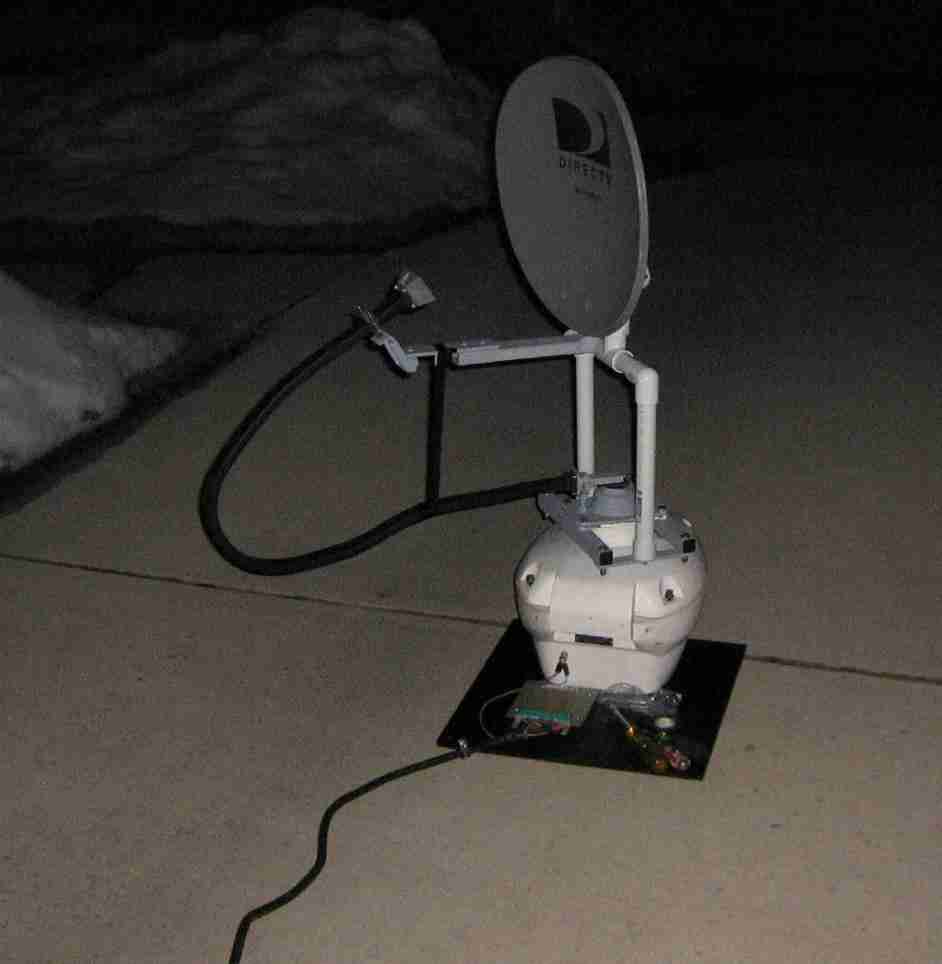
Experimental GBPPR tactical battlefield and air surveillance radar in operation.
You may need to fiddle with the elevation angle a bit during operation for better coverage of the area you want to monitor. The offset feed kinds messes with you...
The flexible waveguide is a little too long, so it's secured to the dish feed arm using some tape.
A piece of polystyrene should be placed over the feed horn to weatherproof it a bit.
You can't legally use marine radar frequencies on land, but Obama can't legally be president - so it all works out...
As the magnetron ages, its output frequency will shift a little.
To compensate for this, there is an adjustment for tweaking the main local oscillator tuning frequency. This is the potentiometer shown above and is located inside the display unit. It can be adjusted between +5V and +35V. The main tuning knob on the display unit is mostly for use as fine tune control.

Example of a DirecTV SlimLine dish.
Dishes of these "orange peel" style are ideal for radar use as they have a narrow horizontal beamwidth and larger vertical beamwidth.