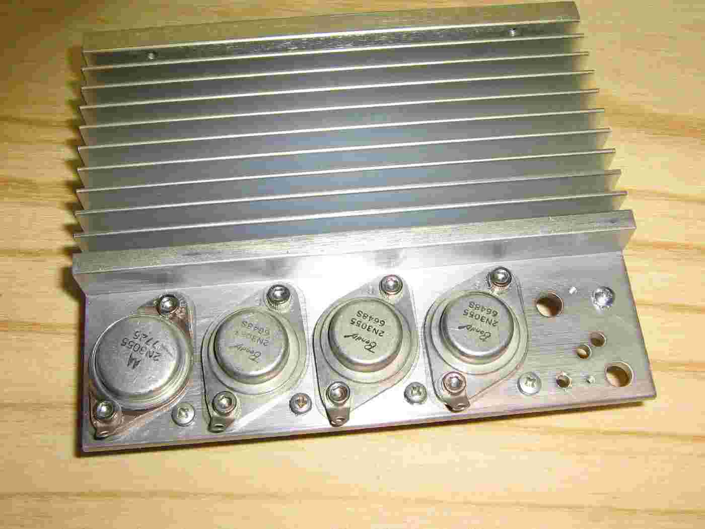
Mounting the 2N3055 pass transistors to the heatsink.
The heatsink was salvaged from an old power supply, and is probably undersized for this application.
Use mica washers or thermal grease on the bottom of the transistors to help with heat dissipation.
Try to use transistors from the same manufacturing lot, if possible.
The solder tabs are for the common-collector wire connections.
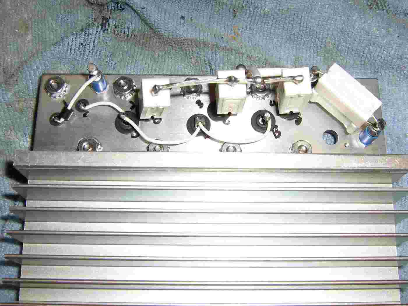
Base and emitter wiring connections to the 2N3055 transistors.
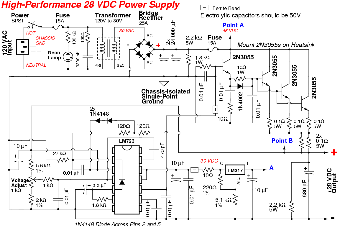
0.1 ohm / 5 watt resistors are used for current equalization between the transistors and two 0.1 ohm resistors are used in parallel to set the current limit control of the LM723 regulator IC.
Because I didn't use sockets for the 2N3055 transistors, you'll have to isolate the heatsink from the project case as it will be at the collector's voltage potential.
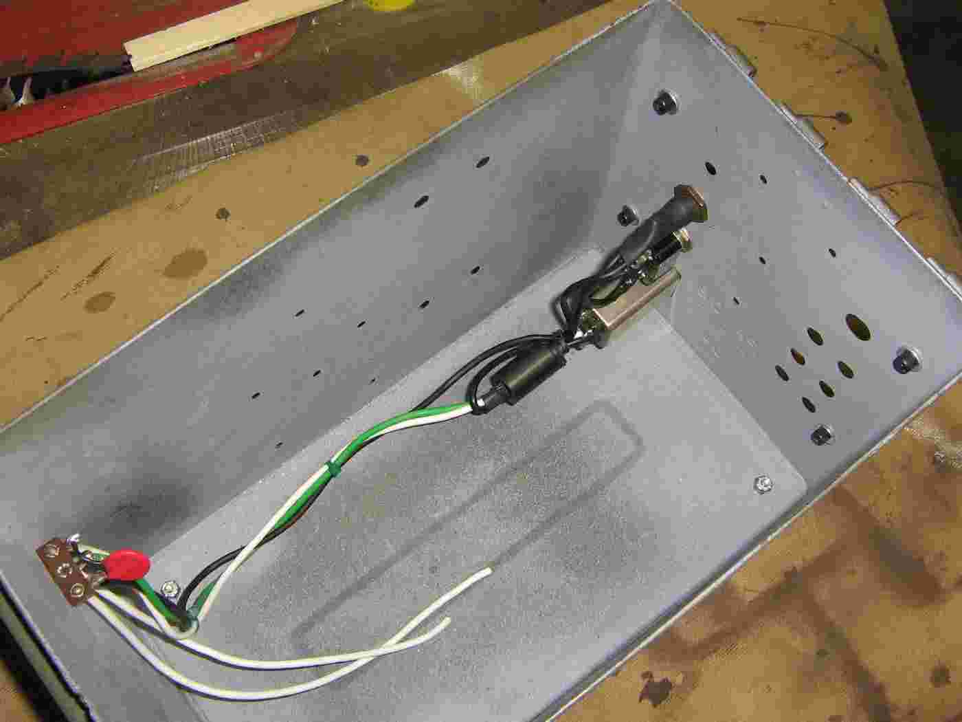
120 VAC input power connections to the project case.
The 120 VAC mains connector is a filtered IEC-type. A large ferrite bead was slipped over the incoming mains lines to suppress any RF interference.
The large red thing on the left is a 150 volt Metal-Oxide Varistor (MOV) to suppress any voltage spikes on the incoming power line. It is placed across the hot and neutral lines. MOVs are available at Radio Shack.
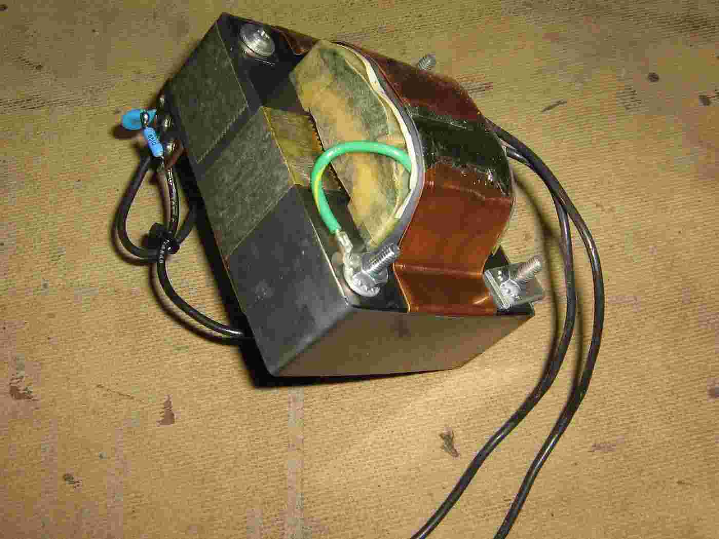
Hamfest transformer with a 30 VAC secondary.
The transformer is a little too small for this application, but that's all I could find.
A terminal strip is used for the primary connections and to mount a resistor/capacitor snubber circuit.
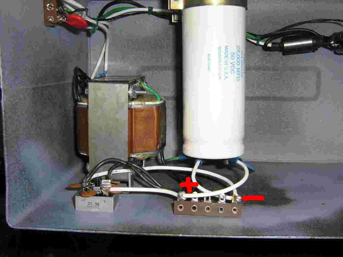
Mounting the transformer, bridge rectifier block, and the transformer's rippler capacitors.
0.01 µF cacacitors are added across each terminal of the rectifier block to suppress EMI. The bridge rectifier block is mounted to the case with some thermal grease to act as a heatsink.
Note the use of a single-point isolated ground system. The project case will be at "Earth" ground, while the negative terminal of the power supply will be isolated and tied to a common point on the output of the bridge rectifier.
The terminal strip serves and a central location for tapping the output from the ripple capacitors.
Additional front-panel wiring.
The NEGATIVE output voltage banana jacks are tied to a single-point ground.
The large capacitor on the right-side is the final 680 µF output filter capacitor.
The fuse holder on the lower-right is blown if the over-voltage protection SCR fires.
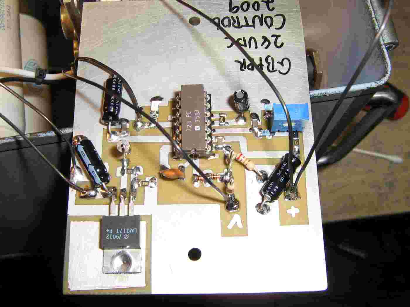
LM723-based voltage regulator board.
1% tolerance metal-film resistors should be used in the voltage divider sections.
1/4 watt resistors should be used in the current limiting section.
The tab of the LM317 voltage regulator should be isolated from the circuit's ground.
The 1 kohm voltage adjust potentiometer can be panel-mounted, if desired.
Use a socket for the LM723 so you can easily replace it.

Mounting the 2N3055 heatsink assembly and the voltage regulator board.
The voltage regulator's circuit board is isolated from the case using nylon hardware.
The heatsink is isolated from the case using head gasket material to maintain a good thermal contact.
The large white rectangle is a ferrite bead which is attached to the POSITIVE output leads.
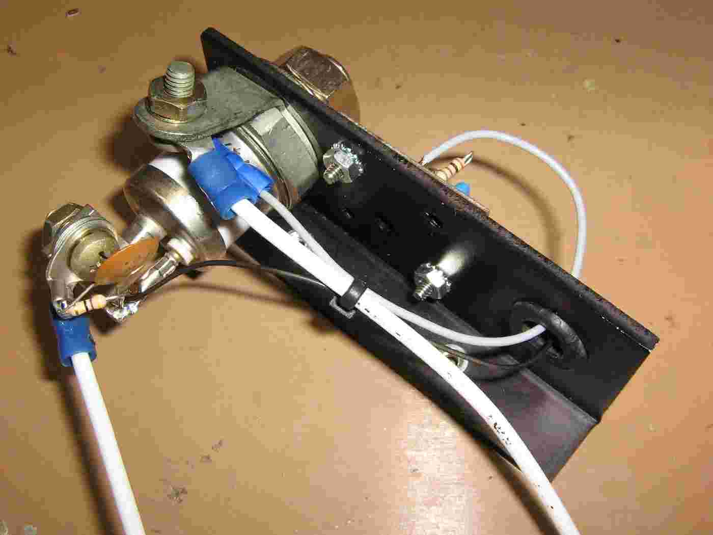
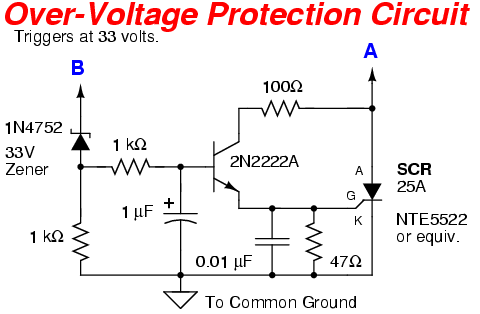
Over-voltage Silicon-Controlled Rectifier (SCR) circuit.
This SCR fires, blowing a fuse, should the power supply's output voltage exceeds 33 volts.
The large SCR was salvaged from a hamfest. Any high-current / 100 volt SCR should work.
Be sure to mount the SCR on some type of heatsink, as it can get hot when triggered.
Also be sure the connecting wires can handle the high-current drawn until the fuse blows.
The anode of the SCR is isolated from the L-bracket using mica washers.
The 47 ohm drain resistor and 0.01 µF capacitor are mounted directly across the SCR's gate terminal to it's grounded cathode.
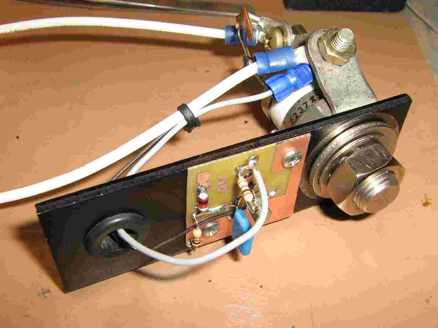
Over-voltage circuit board.
The little orange thing is a 1N4752 33 volt Zener diode.
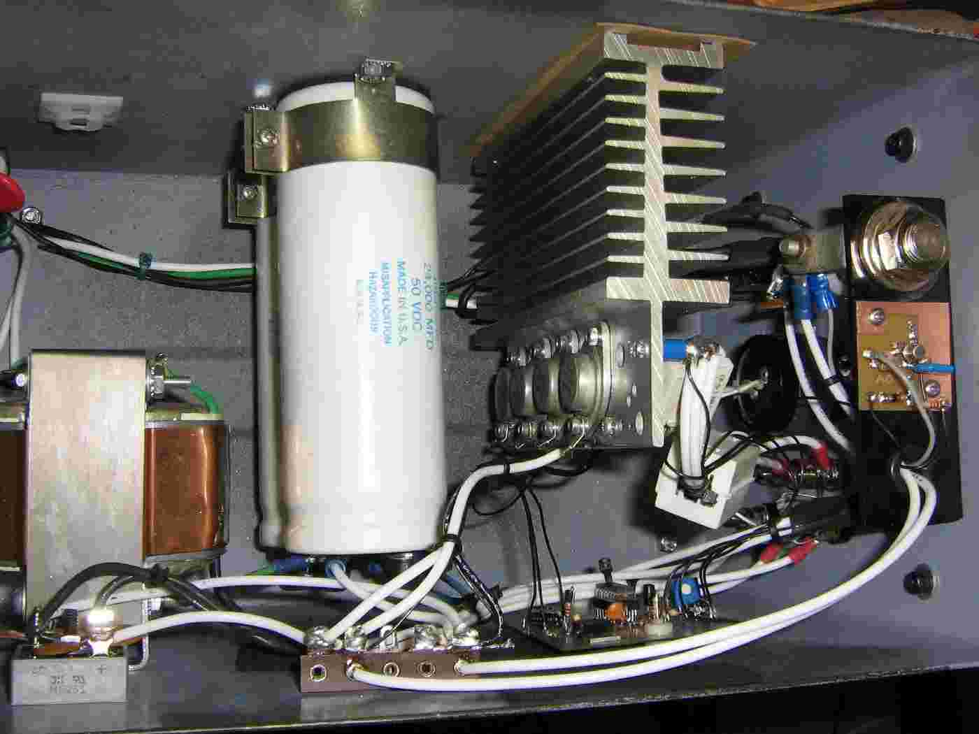
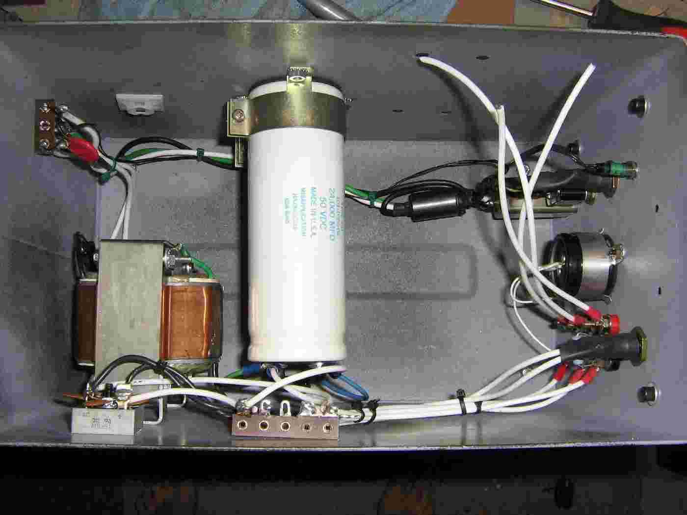
Completed 28 volt power supply internal overview.
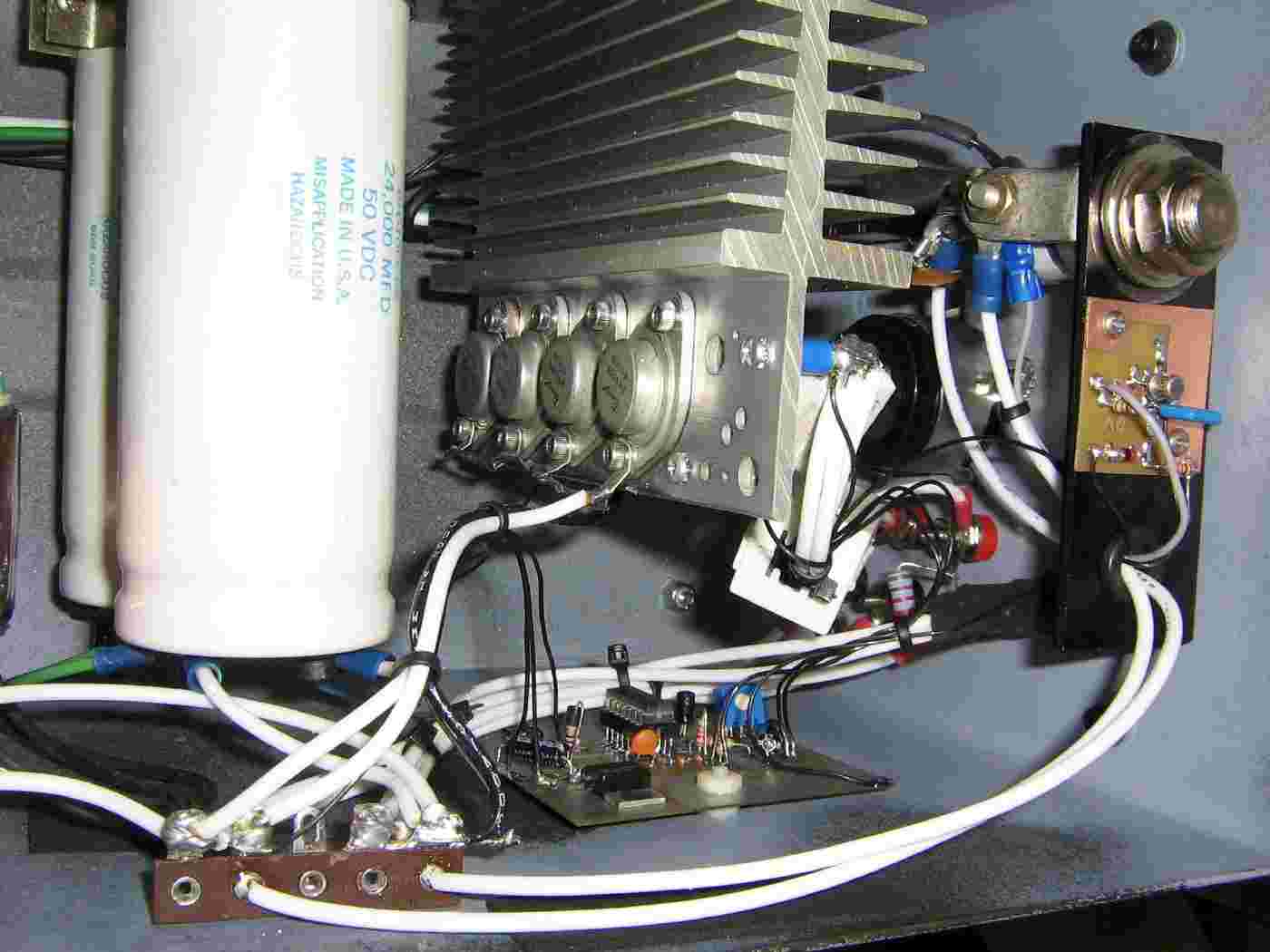
Completed power supply alternate view.
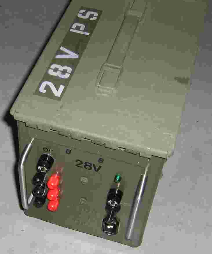
Outside case front-panel overview.
The voltage outputs are via a series of banana jacks.
The fuse on the upper-left is for the over-voltage circuit.
The fuse, switch, and socket on the right-side are for the incoming 120 VAC power.