31 October 1999: Link to final part of transcription, Appendixes B-M:
nt1-92-B-M.htm
28 October 1999: Link to the
distribution list of NSTISSAM
TEMPEST/1-92.
26 October 1999
Source: Hardcopy from the National Security Agency received October 21, 1999.
Released in response to an FOIA
request dated May 18, 1998. Of twenty-two TEMPEST-related documents
requested, only parts of two were released.
NSA wrote that most remain
classified as SECRET and unreleasable. An
appeal for additional
releases has been filed.
This is a third part of transcription of a 172-page document in which classified
sections, about half of the volume, have been redacted (indicated by xxxxxxxx).
Balance of transcription is underway and will be offered here as completed.
First part of transcription, Appendix A:
nstissam1-92a.htm
Second part of transcription, Table of Contents and Sections 1-5:
nt1-92-1-5.htm
The other release, NSA/CSS Regulation 90-6, Technical Security Program,
a 12-page document:
nsa-reg90-6.htm
Classification symbols: (U) = unclassified, (C) = classified, FOUO = for
official use only. Overstrikes in the original.
For comprehensive TEMPEST stuff (non-secret, that is) see The Complete,
Unofficial TEMPEST Information Page:
http://www.eskimo.com/~joelm/tempest.html
From Table of Contents
6 DOCUMENTATION AND CERTIFICATION REQUIREMENTS
6.1 Introduction
6.2 Test Plan Requirements/Contents
6.3 Data Recording
6.3.1 Correlated Emanations
6.3.2 Peak Emanations
6.3.3 Number of Measurements
6.3.4 Data Sheets
6.3.5 Emanation Recordings
6.3.6 Graphs of Test Results
6.3.7 Emanation Designators
6.4 Test Instrumentation Certification Report
6.5 Facility Certification Requirements
6.6 Test Setup Ambient Certification
6.7 Test Report
6.8 Abbreviated Documentation and Certification Requirements
6.8.1 Test Plan/Report Requirements and Contents
6.8.2 Data Recording
7. INSTRUMENTATION REQUIREMENTS
7.1 Introduction
7.2 Detection Systems: General Requirements
7.3 Detection System Sensitivity (DSS) Measurements, General
7.3.1 Introduction
7.3.2 DSS Measurements, Method A: Tunable Detection System Without Demodulator
and Non-tunable Detection System
7.3.3 DSS Measurements, Method B: Tunable Detection System With Demodulator
7.3.4 DSS Measurements, Method C: Tunable Detection System With Demodulator
(d.c.-coupled-output)
7.3.5 DSS Measurements, Optional Method D (IG): Tunable Detection Systems
Without Demodulator and Non-tunable Detection System
7.4 6 dB and Impulse Bandwidth Requirements, Tunable and Non-tunable Detection
Systems
7.5 Signal Measurement Standards
7.5.1 Impulse Generators
7.5.2 Sine Wave Generators
7.6 Calibration Requirements and Operational Check
8 TEST ENVIRONMENT
8.1 Introduction
8.2 Test Chamber
8.3 Test Configuration
8.3.1 Equipment: Under Test Grounding Configuration
8.3.2 EUT Ground Plane
8.3.3 Test Detection System
8.3.4 EUT Exercising Equipment
8.4 Test Setup Ambient Signal Control
9. EQUIPMENT UNDER TEST OPERATION
9.1 Operation
9.1.1 EUT Signaling Rate, Digital Signals
9.1.2 EUT Signaling Rate, Analog Signals
9.1.3 For Tunable Analog Voice Tests
9.1.4 For Non-Tunable Analog Voice Tests
9.2 Test Pattern
10. EMANATIONS SEARCH
10.1 Introduction
10.2 RED Signal Identification/Selection and General Search Requirements
10.2.1 General
10.2.2 RED Signal Type and Signal Source, Definition of
10.2.3 RED Signal Identification/Selection
10.2.4 Test Categories/Criteria
10.2.5 Procedure 1: Search for Correlated Emanations
10.2.6 Procedure 2: Search for Peak EUT Emanations
10.2.7 Search Optimization
10.3 Test Media Examinations
10.3.1 Electromagnetic Radiation
10.3.2 xxxxxxxxxx
10.3.3 xxxxxxxxxx
10.4 xxxxxxxxxx
10.4.1 xxxxxxxxxx
10.4.2 xxxxxxxxxx
10.4.3 Non-tunable Frequency Coverage and Bandpass Requirements
11. EMANATIONS MEASUREMENTS
11.1 Introduction
11.2 General
11.3 Measurement Accuracy
11.4 Emanations Measurement Procedures
11.4.1 Correlated and Peak EUT Emanations
11.4.2 General Measurement Methods
11.4.3 Application of Measurement Methods
11.5 Signal and Noise Measurements
11.5.1 General
11.5.2 Procedure 1: Statistical Measurements
11.5.3 Procedure 2: Visual "A-Scope" Measurements
11.5.4 Relating Statistical and Visual Measurements
12. LIMITS
12.1 General
12.2 Electromagnetic Radiation Limits
12.2.1 Electric Radiation Limits
12.2.2 Magnetic Radiation Limits
12.3 BLACK Line Limits
12.3.1 BLACK Line Conduction Limits
12.3.2 xxxxxxxxxx
12.3.3 xxxxxxxxxx
12.4 RED Line Limits
[Pages 6-1 to 6-6]
UNCLASSIFIED
SECTION 6 -- DOCUMENTATION AND CERTIFICATION
REQUIREMENTS
6.1. (U) Introduction. -- This section details the documentation and
certification requirements for verifying compliance with various levels of
this standard. Sections 6.2 through 6.7 detail the requirements for Levels
I and II and Section 6.8 for Level III.
6.2. (U) Test Plan Requirements/Contents. -- Prepare a test plan that
details the means of implementing and applying the test procedures to be
performed in order to verify compliance with the applicable TEMPEST requirements
of this document. The test plan, when executed, shall demonstrate and delineate
wherein the equipment meets or fails to meet the requirements herein. The
test plan shall include, but not necessarily be limited to, the items listed
in the TEMPEST test plan outline in Appendix L.
6.3. (U) Data Recording.
6.3.1 (U) Correlated Emanations. -- When correlated emanations are detected,
they shall be measured and recorded regardless of whether the level is less
than or in excess of the limit. When the level of the correlated emanation
is less than the limit, it is not required to make any further determination
as to whether the signal is CE or DRE, unless otherwise specified by the
sponsoring organization. Where correlated emanations are not detected, sufficient
measurements shall be made to ascertain the spectrum of TEMPEST-limited ambient
emanations from the EUT and test environment.
6.3.2 (U) Peak Emanations. -- When searches are made for peak emanations,
record all emanations regardless of whether above or below the limit. When
the level of the peak emanation is less than the limit further identification
is not required (e.g., whether ENVA, EUTA, etc.), unless otherwise specified
by the sponsoring organization. For automated testing (Appendix E), the use
of peak ambient emanation levels is acceptable, provided such emanation levels
are below the applicable limits.
6.3.3 (U) Number of Measurements. -- It is the intent of this document that
sufficient measurements be made to ascertain the levels of the detected
emanations and the frequency range over which the emanations are to be found.
To achieve this, measurements should be made at definitive peaks and valleys
over the test frequency range. The total number of emanation and noise
measurements recorded and plotted shall be a minimum of three per decade
of test frequency or three per detection system frequency band (near the
beginning, center, and end of the decade or band), whichever is the greater
number of measurements. Record all signal measurements in the units of the
limit to which the measurements are to be compared.
6.3.4 (U) Data Sheets. -- All data taken during testing of the EUT shall
be recorded on data sheets. The data sheets shall include, but not necessarily
be limited to, the following items:
a. (U) Date data was taken.
b. (U) Nomenclature of EUT, including model number, manufacturer, serial
number and any other designation needed to identify it.
c. (U) Test performed (test reference number, if applicable), including line
tested (designation, pin number, etc.) and function of line for conduction
tests.
d. (U) Reference to approved test plan, applicable test plan items, EUT and
detection system test setup.
e. (U) EUT operational mode or any other test conditions describing operation
of EUT.
f. (U) Name(s) of person(s) performing tests, if different from test plan.
g. (U) Monitor, i.e., RED signal.
h. (U) Signal processing mode (serial or parallel, nonrepetitive or repetitive).
i. (U) For each measurement, record the following data.
(1) (U) Test frequency.
(2) (U) Overall detection system bandwidth. (Also, record predetection bandwidth
used when employing a Demodulator.).
(3) (U) Calibrated source (signal generator, impulse generator) reading in
appropriate units.
(4) (U) Conversion and correction factors listed separately and identified.
(5) (U) Adjusted reading (absolute emanation level) in appropriate units.
(6) (U) Specified TEMPEST limit at the particular test frequency.
(7) (U) Identification of emanation (see Paragraph 6.3.7).
(8) (U) Description of detected emanation (timing, 60 Hz, etc.).
(9) (U) Comments, e.g., any observations considered helpful in identifying
or describing detected emanations or special test conditions.
6.3.5 (U) Emanation Recordings. -- Provide recordings (photographs and/or
strip charts or other data formats specified by the sponsoring organization)
for EUT emanations that exceed the applicable limits herein. Recordings,
representative of correlated emanations, shall be provided, whether above
or below the applicable limits. Sufficient recordings shall be made to
substantiate conclusions by the tester as to compliance or noncompliance
of the EUT with this document or, when applicable, to provide adequate
description of EUT emanations to allow the U.S. Government to determine
compliance via signal analysis. The recordings shall be captioned and be
accompanied by a brief description of what is being presented. Denote applicable
timing, amplitude, and other relevant data (e.g., information ratio (IR)
when calculated). The recordings shall clearly show the emanations.
6.3.6 (U) Graphs of Test Results. -- Present all measured EUT emanations
on graphs, together with ambient noise and applicable limits. Graphs shall
be plotted in dB on a linear scale versus frequency on a logarithmic scale.
Graphs shall be scaled horizontally and vertically to show effectively the
required test frequency range and the recorded levels. Units of measurement
shall be included and shall be the same as those provided on the limits.
6.3.7 (U) Emanation Designators. -- When performing searches for correlated
emanations the following emanation designators1 shall be used
for identifying detected emanations and ambient signs (see Figure 5-1) on
data sheets and graphs and for other results presented in the EUT test report:
CORR E -- correlated emanations which consist of either:
CE -- compromising emanations; specify whether above or below limit; or
DRE -- data related emanations; correlated emanations which are not compromising.
OE -- other emanations which consist of either:
EUTA -- EUT TEMPEST-limited ambient (noncorrelated EUT emanations); or
ENVA -- environmental TEMPEST-limited ambient.
DSN - detection system noise.
Note: DSN normally does not represent an emanation as such; however,
the designator is included here for completeness.
___________________
1 emanation designators are normally not applied to peak emanation
searches.
6.4. (U) Test Instrumentation Certification Report. -- All instrumentation
(i.e., detection system and signal generators) used for TEMPEST testing must
be certified and approved prior to performing laboratory TEMPEST evaluations.
To obtain certification approval, the testing organization must provide
descriptions and detection system sensitivity measurements of the test
instrumentation and submit this data in a certification report to the sponsoring
organization. The certification approval will be valid for a period of three
years from the date of approval, unless otherwise specified by the sponsoring
organization. (This does not alleviate the requirement that test instrumentation
operation and calibration be verified at six-month intervals.) The test
instrumentation certification report shall include, but not necessarily be
limited to, the following items:
a. (U) Name of organization or firm conducting the test, contracting agency,
and contract number.
b. (U) Date(s) of tests.
c. (U) List of the entire complement of TEMPEST test instrumentation, including
the nomenclature, identification number, bandwidths,2 frequency
ranges, and manufacturer of receivers, antennas, probes, signal generators,
oscilloscopes, etc.
d. (U) Sensitivities for each bandwidth used for both tunable and non-tunable
detection system test configurations. For each media searched, the sensitivity
data and bandwidths3 used shall be presented in graphic form which
compares the measured detection system sensitivity with the appropriate TEMPEST
limits.
e. (U) Pertinent control settings of the test devices and instruments.
f. (U) All conversion and correction factors used for the applicable test
frequency ranges.
g. (U) Block diagrams of the detection systems and calibration signal sources
used.
h. (U) An explanation and justification of noncompliance with the sensitivity,
bandwidth and frequency requirements. Specify the steps that were taken in
an effort to comply with these requirements.
_____________________
2 Include the overall detection system bandwidths at both the
pre-detection and post-detection outputs.
3 Include both pre-detection and overall detection system bandwidths
when the post-detection output to be used.
6.5. (U) Facility Certification Requirements. -- The test facility
must be certified and approved prior to performing laboratory TEMPEST
evaluations. To obtain facility certification approval, the testing organization
must provide descriptions and ambient measurements of its test facilities
and submit this data in a facility certification report to the sponsoring
organization. Facility certification approval will be valid for a period
of three years from the date of approval, unless otherwise specified by the
sponsoring organization. The facility certification report shall include,
but not necessarily be limited to, the following items:
a. (U) Name of organization or firm conducting the certification tests,
sponsoring organization and contract number (if applicable).
b (U) Address of the organization or firm where test is to be conducted.
c. (U) Location of test facility within plant.
d. (U) Description of facility, e.g., manufacturer and construction of shielded
enclosure, description or cable entrances, lighting, available electrical
power, etc.
e. (U) Date(s) of certification tests.
f. (U) Levels versus frequency plot compared with the appropriate TEMPEST
limits of radiated ambient signals in the test environment measured with
tunable and non-tunable detection systems for the highest and lowest applicable
test categories.
g. (U) Levels versus frequency plot compared with the appropriate TEMPEST
limits of ambient levels on d.c. and a.c. main electrical powerlines under
load when measured with tunable and non-tunable detection systems for the
highest and lowest applicable test categories, if such lines will be used
to power the EUT during tests.
Note: (U) The test chamber powerlines shall be filtered such that
the ambient levels are equal to or less than the tunable BLACK line conduction
(BLC) limits (Figure H-3 and Table H-3) at test frequencies above 150 times
the powerline frequency when measured with a tunable detection system. This
measurement shall be taken using a line impedance stabilization network (LISN)
with the load side terminated in a resistive load drawing the same current
(+/- 25%) as the EUT.
h. (U) Description of any unusual or potentially bothersome signal conditions,
not evident from graphic data, which might cause masking.
i. (U) List of instrumentation, including serial numbers.
j. (U) An explanation and justification of noncompliance with facility
requirements. Specify the steps which were taken in an effort to comply with
these requirements.
6.6. (U) Test Setup Ambient Certification. -- After the test setup
has been determined, and before formal TEMPEST testing of the EUT has begun,
the ambient signals originating from the test setup must be evaluated by
the testing organization. The ambient signal levels must be documented in
a test setup ambient certification report, which shall be submitted as an
appendix to the test report. Submission and approval of the test setup ambient
certification report is not required prior to testing, unless otherwise specified
by the sponsoring organization. This certification report shall include,
but not necessarily be limited to, the following items:
Note: Items a., f., and g. are required only when the sponsoring
organization requires submission and approval of this report prior to testing.
a. (U) Name of organization or firm conducting certification tests. sponsoring
organizations, and contract number, if applicable.
b. (U) Date(s) of tests.
c. (U) Functional description of EUT exerciser equipment, if different from
that used for tests of the EUT.
d. (U) Levels versus frequency plot of radiated and conducted TEMPEST-limited
or peak ambient signals in the test environment for the highest and lowest
Rd or Rt data rates, (measured with the tunable and nontunable detection
systems and with the test setup installed). (Refer to Paragraph 8.4.)
Note: (U) Present the data obtained above in graphic form which compares
the ambient levels with the applicable TEMPEST limits.
e. (U) Description of any unusual or potentially bothersome ambient conditions,
not evident from graphic data which might cause masking.
f. (U) List of instrumentation including serial numbers, used during
ambient-level survey.
g. (U) Block diagrams of EUT and detection system setups used during
ambient-level survey.
h. (U) An explanation and justification of noncompliance with the ambient-level
requirements. Specify the steps that were taken in an effort to comply with
these requirements.
Note: (U) If the requirements of this paragraph are met, it follows
that those of 6.5 are also met.
6.7. (U) Test Report. -- At the completion of the TEMPEST tests. a
report shall be written which contains, at a minimum, the following information:
a. (U) Abstract.
b. (U) Name of organization or firm conducting the tests, the sponsoring
organization, and the contract number.
c. (U) Date(s) of tests.
d. (U) Test plan (Paragraph 6.2) and test setup ambient certification report
(Paragraph 6.6) as appendices.
e. (U) Date of most recent calibration of test instrumentation prior to TEMPEST
tests.
f. (U) Descriptions of any deviations from the test plan.
g. (U) Photographs or pictorial diagrams of detection system and EUT test
setups with proper identification.
h. (U) Critical installation details determined as a result of either preliminary
or formal testing, which are necessary in order that the EUT meets the limits
of this document.
i. (U) Description of supplementary theoretical and empirical work that was
accomplished.
j. (U) Identification and description of suppression devices using schematics,
performance characteristics and drawings, except where these data are required
of the tester in other documents. If required of the tester in other documents,
the appropriate document(s) shall be referenced.
k. (U) Test results, including the following items:
(1) (U) Data, including all emanation levels and noise graphed with the
appropriate TEMPEST limit. An easily interpreted legend shall be used to
identify the various emanation designators. (See Paragraph 6.3.7.)
(2) (U) A concise narrative description of the emanations detected in each
test media and the frequency range in which these emanations were detected.
(3) (U) Visual recordings, with appropriate reference to test plan items,
illustrating each type of detected correlated emanation.
(4) (U) Description of any phenomenon or emanation, encountered during testing,
that lies outside of the specific requirements of this document, and which
may conceivably compromise the national security information being processed
by the EUT.
(5) (U) Data sheets, when requested by the sponsoring organization.
l (U) Tabular summary of compromising emanation (CE) levels exceeding limits
that shall include, but not necessarily be limited to the following items:
(1) (U) Identification of line or test medium (i.e.. electric radiation (ER)
or magnetic radiation (MR), with reference to appropriate test plan item.
(2) (U) Identification of RED signal to which above-limit CE is correlated.
(3) (U) Frequency ranges of above-limit CE.
(4) (U) Maximum level of above-limit CE normalized to (i.e., how much above)
the appropriate limit. Indicate referenced limit.
(5) (U) Reference sections of TEMPEST test report or test results that further
explain the extent of CE on that particular line or in that test medium.
m. (U) Description of signal analysis procedures and techniques used.
n. (U) Conclusions.
o. (U) Recommendations.
p. (U) Names of test personnel.
q. (U) Completed TEMPEST profile. (See Appendix M.)
6.8. (U) Abbreviated Documentation and Certification Requirements.
-- When permitted, the following reduced formats can be used to satisfy the
documentation and certification requirements of this document.
6. 8. l (U) Test Plan/Report Requirements and Contents. -- A test plan/report
which contains, at a minimum, the following information:
a. (U) Title page including equipment nomenclature, equipment file number
(if applicable). name of organization or firm conducting the tests, sponsoring
organization, contract number, names and original signatures of TEMPEST
personnel, date(s) of test.
b. (U) Description of EUT.
c. (U) Operating modes.
d. (U) RED signal description.
e. (U) Test matrix.
f. (U) Test messages.
g. (U) Critical installation details determined as a result of either preliminary
or formal testing which are necessary in order that the EUT meets the limits
of this document.
h. (U) Test results including the following items:
(1) (U) A concise narrative description of all above-limit emanations and
the frequency range in which these emanations where detected.
(2) (U) Description of any phenomenon or emanation encountered during testing,
that lies outside of the specific requirements of this document.
i. (U) Description of signal analysis procedures and techniques used.
j. (U) Conclusions.
k. (U) Completed page one of TEMPEST profile. (See Appendix M).
6.8.2 (U) Data Recording. -- All recorded data shall be maintained for on-call
U.S. Government inspection.
[Pages 7-1 to 7-4]
SECTION 7 -- INSTRUMENTATION REQUIREMENTS
7.1. (U) Introduction. -- The TEMPEST test instrumentation consists
of detection systems and signal measurement standards which shall meet the
performance requirements and operating characteristics specified herein.
Measurements of sensitivity and bandwidth shall be performed as specified.
7.2. (U) Detection Systems: General Requirements. -- Two basic types
of detection systems are required: tunable and non-tunable. All systems shall
have a 50 ohm input impedances with the exception of conducted signal probes
and electric radiation antenna interface amplifiers, which may be high impedance.
Systems shall be selected that meet the frequency range and bandwidths required
by the EUT internal RED signaling rate(s) of the equipment being evaluated.
Systems selected shall meet the appropriate sensitivity requirements.
Pulse-stretching circuits may be used on the output of any tunable detection
system, provided the following requirements are met:
-
Charge time constant < 1/BW
-
Discharge time constant < 10/BW
-
Signal level as observed on the oscilloscope is not reduced by more than
20 percent.
BW is the pre-detection bandwidth of the detection system. Pulse-stretching
circuits shall not be used when measuring the sensitivity or bandwidth of
the detection systems even if the circuit is used during TEMPEST testing.
7.3. (E) Detection System Sensitivity (DSS) Measurements, General.
7.3.1 (U) Introduction.
7.3.1.1 (U) The detection system sensitivity (DSS), as defined in Paragraph
2.1.12. shall be measured for both tunable and non-tunable detection systems
and shall apply to all signal classes. All DSS measurements shall use acceptable
calibration sources (see Paragraph 7.5).
7.3.1.2 (U) Three methods are specified using sine wave substitution sources.
One optional method using impulse generator substitution sources is presented
as an alternative.1 Method A requires a calibrated unmodulated
carrier as the substitution signal, and is applicable when measuring the
DSS at the pre-detection (e.g., IF) output of tunable detection systems and
at the output of non-tunable detection systems. Method B requires a calibrated
sine wave carrier, modulated at 30 percent by a sine wave at any suitable
frequency less than, or equal to, the repetition rate as the substitution
signal, and is applicable when measuring the DSS at the a.c.- or d.c.-coupled
post-detection output. Method C is applicable when measuring the DSS at the
d.c.-coupled post-detection output, where technical limitations prevent the
use of a modulated sine wave carrier as the substitution signal. The required
substitution signal for method C is a calibrated unmodulated carrier. Method
D is an optional method to be used with impulse generator substitution sources.
Method A, B, or C is recommended when sine wave substitution sources are
available.
_____________________
1 Other alternate DSS measurement methods are allowed if justified
and approved by the sponsoring organizations.
7.3.2 (U) DSS Measurements, Method A: Tunable Detection System Without
Demodulator and Non-Tunable Detection System. -- Measurements shall be made
using a calibrated, unmodulated sine wave substitution source. A true rms
a.c. voltmeter of adequate bandwidth (frequency range extending both below
and above the detection system bandpass) shall be connected at the pre-detection
output of the tunable detection system or output of the non-tunable detection
system. The controls on the detection system shall be adjusted to establish
a convenient reading of detection system noise on the output voltmeter. The
calibrated source, with the cw frequency equivalent to the center frequency
of the detection system, shall be adjusted to produce a reading on the output
true rms a.c. voltmeter 3 dB higher than the reading of detection system
noise (signal plus noise-to-noise ratio of 3 dB). The level of the sine wave
source output (expressed in dBµV rms), plus any appropriate
conversion and correction factors, minus 3 dB, is the detection system
sensitivity.
7.3.3 (U) DSS Measurements, Method B: Tunable Detection System With Demodulator.
-- Measurements shall use a calibrated sine wave carrier modulated 30 percent.
A true rms a.c. voltmeter (not necessarily the same voltmeter as used for
Method A) of adequate bandwidth (larger than the detection system bandwidth)
shall be connected at the post-detection output (a.c.- or d.c.-coupled) of
the detection system. The controls on the detection system shall be adjusted
to establish a convenient reading of detection system noise on the output
voltmeter. The calibrated source, with the carrier frequency equivalent to
the center frequency of the tuned detection system, shall then be applied
to the detection system input. The carrier amplitude of the signal substitution
source shall be adjusted to produce a reading on a true rms a.c. voltmeter
that is 3 dB higher, with the carrier modulated 30 percent, than with the
carrier unmodulated (modulation turned off and on). The level of the sine
wave source output (expressed in dBµV rms), plus any appropriate
conversion and correction factors, minus 13 dB, is the detection system
sensitivity.
7.3.4 (U) DSS Measurements, Method C: Tunable Detection Sy stem With Demodulator
(d.c.-coupled output). -- This method is used when technical limitations
prevent the use of a modulated sine wave carrier as a substitution signal.
Measurements shall be made using a calibrated, unmodulated sine wave substitution
source. A true rms a.c. voltmeter of sufficient bandwidth (larger than the
detection system bandwidth), and a d.c. millivoltmeter shall be connected
at the post-detection output (d.c.-coupled) of the detection system. The
calibrated source, with the cw frequency equivalent to the center frequency
of the tuned detection system. shall then be applied to the detection system
input. The substitution source amplitude controls shall be adjusted to produce
a reading on the d.c. millivoltmeter approximately equal to five times the
reading on the true rms a.c. voltmeter at the post-detection output (i.e.,
output signal- (d.c.) to-noise (a.c.) ratio approximately equal to five).
Compute the actual output signal- (d.c.) to-noise (a.c.) ratio in dB. The
level of the sine wave source output (expressed in dBµV rms),
plus any appropriate conversion and correction factors, minus the above computed
output signal- (d.c.) to-noise (a.c.) ratio in dB, is the detection system
sensitivity.
Note: This method assumes a d.c.-coupled output from post-detection
to d.c. meter. In some detection systems there may be an associated d.c.
offset. Under these circumstances, the offset must be nulled out electronically
or taken into account in ensuing calculations. If it is not, significant
error can result because the static d.c. offset can be large in relation
to the small change produced during the sensitivity measurements. Linear
operation is assumed over the range being used.
7.3.9 (U) DSS Measurements, Optional Method D (IG): Tunable Detection Systems
Without Demodulator and Dion-Tunable Detection System. -- Measurements shall
be made using a calibrated IG and converting this measurement to dB ref
1µV rms using the impulse bandwidth (refer to Paragraph 7.4 for
impulse bandwidth). A true rms a.c. voltmeter and a calibrated CRO of sufficient
bandwidth frequency range, extending both below and above the detection system
bandpass, shall be connected to the output of the detection system. With
the IG connected to the input of the detection system and the IG level controls
adjusted so that the detection system output impulsive signal is well below
the noise, note the reading on the true rms voltmeter. Without disturbing
the detection system settings, the IG level controls shall be adjusted to
produce an impulsive signal on the CRO with a peak amplitude equal to five
times the rms noise reading previously noted (14 dB peak signal-to-rms noise
ratio). The level of the IG substitution source (expressed in dB ref
µV/MHz, equivalent rms sine wave), plus the impulse bandwidth
factor {20 log10 [IBW(MHz)]}, minus 14 dB, plus any appropriate
conversion and correction factors, is the detection system sensitivity.
Note: Method D is not recommended when sine wave substitution generators
are available or when the impulsive input/output characteristics of the detection
system are not sufficiently linear over the initial 14 dB range.
7.4. (U) 6 dB and Impulse Bandwidth Requirements, Tunable and Non-Tunable
Detection Systems.
7.4.1 (U) Refer to Appendix G for tables and figures. The detection system
bandwidth requirements specified in this paragraph shall apply to the entire
detection system, including the transducer2 (antenna, voltage
or current probe, etc.) and display device (CRO, strip chart recorder, etc.),
unless it can be shown that the bandwidth of these devices will not restrict
the bandwidth of the remainder of the detection system. The 6 dB bandwidth
of the tunable or non-tunable detection system shall be measured in accordance
with Appendix F if:
a. (U) The 6 dB bandwidth of the detection system is not known or cannot
be calculated within an accuracy of +/-20 percent.
b. (U) There is reason to doubt the manufacturer's published 6 dB bandwidth
figures for any of the devices in the detection system (the most band-limited
device being the most critical).
c. (U) Requested by the authority sponsoring the tests.
7.4.2 (U) The impulse bandwidth of the tunable or non-tunable detection system
shall be measured in accordance with Appendix F if:
a. (U) There is reason to doubt the manufacturer's published impulse bandwidth
figures.
b. (U) There is reason to believe that the impulse bandwidth of the detection
system cannot be approximated by the 6 dB bandwidth of the detection system
within an accuracy of +/-20 percent.
c. (U) Requested by the authority sponsoring the tests.
7.4.3 (U) The 6 dB bandwidth requirements for all tunable and non-tunable
detection systems shall be based on the EUT internal RED signaling rates
determined in Paragraph 5.4. Bandwidths for tunable detection systems shall
comply with the requirements specified in Figure G-2. For tunable detection
systems which employ a Demodulator, the pre-detection bandwidth shall not
be greater than three times the overall detection system bandwidth, as measured
in accordance with Appendix F. The pre-detection bandwidth requirement applies
to the intermediate frequency (IF) bandwidth for detection systems employing
the heterodyne principle. The bandpass of non-tunable detection systems shall
conform to the requirements presented in Table G-3. Tunable detection systems
used for TEMPEST testing equipment may be comprised of non-tunable
fixed-bandwidth amplifiers, provided the applicable bandwidth sensitivity
and test frequency requirements of this document are met. The shape factor
(see glossary) of the tunable detection systems shall not exceed
10:13, when measured at the center of each decade of frequency
or the center of each tuning bands whichever is the greater number of
measurements. The shape factor shall be measured if:
a. (U) The shape factor of the detection system is not known.
b. (U) There is reason to doubt the manufacturer's published shape factor
figures for any of the devices in the detection system (the most band-limiting
device being the most critical).
c. (U) Requested by the authority sponsoring the tests.
7.4.4 (U) The roll off of the non-tunable detection system gain-frequency
response (each side or "skirt") shall be no less than 40 dB/decade.
_____________________
2 The bandwidths of some transducers (e.g., antennas, current probes)
are very difficult or impractical to measure. In these cases, bandwidth
measurements need not be made on the device, but precautions shall be taken
to assure that the device does not limit the overall detection system bandwidth.
3 An exception to the 10:l shape factor, defined at the 60 dB and
6 dB points, shall be made only when the response of the detection system
or device does not have sufficient dynamic range to allow a frequency measurement
at the 60 dB point. In this event, the frequencies at the 40 dB point shall
be measured; the ratio of the 40 dB bandwidth to the 6 dB bandwidth shall
not exceed 6.5:1.
7.5. (U) Signal Measurement Standards. -- The acceptable calibration
standards, for the purpose of this document, are impulse generators and sine
wave generators.
7.5.1 (U) Impulse Generators. -- Impulse generators (IGs) shall conform to
the following requirements:
a. (U) Calibrated in dBµV/MHz (equivalent rms sine wave) (peak
minus 3 dB) to a 50 ohm resistive load.
b. (U) Flat spectrum (+/-2 dB) over the detection system bandwidth at all
test frequencies applicable to the bandwidth.
c. (U) Amplitude accuracy (+/-2 dB) calibrated at a minimum of three frequencies
including the maximum, minimum, and center frequencies of the range over
which they are to be used. Calibration of impulse generators shall be
accomplished in accordance with the procedures in Appendix K.
7.5.2 (U) Sine Wave Generators. -- Sine wave generators shall conform to
the following requirements:
a. (U) Frequency accuracy: +/-2 percent.
b. (U) Harmonic and spurious outputs 30 dB or more down from power level
of the fundamental signal frequency. RF coupling which bypasses the signal
generator attenuator should not induce errors in any measurements.
c. (U) Amplitude accuracy:
+/-1 dB for fc < 1 GHz
+/-3 dB for fc > 1 GHz
7.6. (U) Calibration Requirements and Operational Check. -- Prior
to the beginning of EUT evaluation. at the beginning of each working day,
or at the request of the sponsoring organization, all test instrumentation
shall be checked to assure proper operation. The operation and calibration
of the instrumentation shall be verified at six-month intervals or immediately
after exposure to conditions that might affect the calibration. All
instrumentation (detection system, signal measurement standards, etc.) shall
be calibrated in accordance with a recognized calibration procedure e.g..
MIL-STD-45662. If, during any of the above tests, an equipment is found to
be out of calibration or a departure from the requirements of this document
is noted, the tester shall:
a. (U) Determine the cause(s) of deviations.
b. (U) Make necessary repairs and adjustments.
c. (U) Request the sponsoring organization to determine the necessity for
rerunning affected tests.
[Pages 8-1 to 8-3]
UNCLASSIFIED
SECTION 8 -- TEST ENVIRONMENT
8.1. (U) Introduction. -- The electromagnetic environment in which
TEMPEST tests are performed influences the ability to detect emanations from
the EUT. Therefore, tests must be performed in a test environment wherein
ambients are not above the applicable TEMPEST limits. This normally requires
that the EUT be installed within a shielded test enclosure with the test
instrumentation and exercising equipment located externally. Strict attention
must be paid to grounding and the test setup to eliminate extraneous coupling
paths which could produce erroneous test results.
8.2. (U) Test Chamber. -- The test chamber shall provide a test
environment where the internal spatial ambient signal is below the applicable
TEMPEST limits. This normally requires an electromagnetically shielded enclosure.
The test chamber shall provide a means of isolating the EUT from the
EUT-exercising equipment and the test detection system (except the transducer).
The test chamber shall be large enough to permit the test antenna being used
to meet the requirements of Paragraph 10.3.1 and Figure 10.7. RF absorption
material may be positioned within the test chamber to minimize measurement
anomalies caused by standing waves and/or reflections. If absorption material
is used, the certification report shall contain details on the type of material
used and location relative to the EUT and enclosure walls in three dimensions.
8.3. (U) Test Configuration.
8 3.1 (U) Equipment Under Test Grounding/Configuration.
8.3.1.1 (U) The EUT shall be grounded, as in a normal installation, and shall
be placed on a ground plane when tests are performed in a shielded enclosure.
When tests are not performed in a shielded enclosure, a ground plane is not
required. The ground plane shall consist of a table with a copper or brass
top surface, unless the weight and/or size of the EUT makes this impractical;
in this case, the ground plane shall be located on the floor of the test
chamber. This ground plane shall meet the requirements of Paragraph 8.3.7.
When bonding straps are required to complete the test setup (exclusive of
bonding straps from the ground plane to the shielded enclosure), they shall
be identical to those specified for normal installation. When an external
lug or connector pin is available on the EUT for a ground connection and
when in the normal operational installation the lug or pin is grounded, the
lug or pin shall be bonded to the ground plane. If the installation requirements
specify that the EUT not be grounded, or if the installation conditions are
unknown, the EUT shall not be grounded. In the latter case, the EUT and ancillary
cables shall be placed on, but isolated from, the ground plane with nonconductive
materials or standoff insulators 4 to 6 centimeters in height.
8.3.1.2.a (U) Level I.
(U) The type and installation of conduits and cables used in the EUT setup
shall be the same as that specified for the operational installation. Otherwise,
justification must be provided in the TEMPEST test plan (See Paragraph 6.2)
as to why this will not be done.
8.3.1.2.b (U) Levels II and III.
(U) The type and installation of conduits and cables used in the EUT test
setup shall be the same as that specified for the operational installation.
When conduit is not required the EUT shall be installed as shown in Figure
8-1 to provide a standard test configuration. An appropriate two meter long
unshielded power cord extension shall be connected between the end of the
provided power cord and the PLISN. The PLISN is used to provide a standard
termination for the power line. A signal line cable shall be at least two
meters long. The signal line shall be installed as described in the notes
on Figure 8-1. Additional signal lines may be connected, as required, between
the shielded enclosure and the termination box shown in Figure 8-1. Provide
justification in the test plan if the EUT test configuration cannot conform
to that specified in this paragraph.
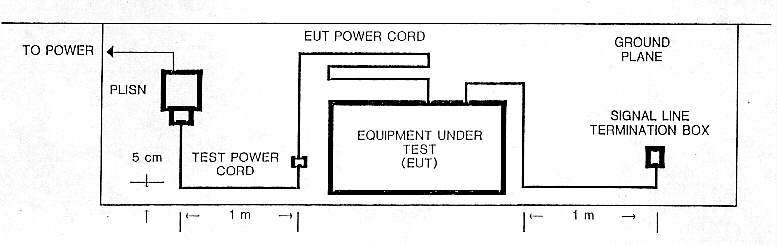
Note
1: Unshielded test power cord extension connecting PLISN to EUT power cord
shall be two meters long with one meter section located as shown on edge
of test ground plane (see Note 2).
2: All power and signal cables shall be 5 cm above the ground plane. Excess
EUT power cord to be coiled behind equipment.
3: EUT shall be a minimum of 20 cm from the shielded enclosure wall.
4: The one meter segments of power and signal cable shall start no further
than 10 cm from the EUT.
5: Signal line termination box shall be grounded using the shield of a shielded
cable or the ground wire of an unshielded cable.
UNCLASSIFIED
Figure 8-1. -- Standard Test Configuration (U)
|
8.3.1.3 (U) If either preliminary or formal tests reveal that certain
installation details (reference grounding and shielding) are necessary in
order that the EUT meet specification limits, then such details must be
documented in the test report (see Paragraph 6.7). Likewise, any EUT test
installation details which differ from that provided in the TEMPEST test
plan shall also be documented in the test report.
8.3.2 (U) EUT Ground Plane. -- The EUT ground plane (required for tests performed
in a shielded enclosure) shall consist of a solid copper or brass plate that
has a minimum thickness of 0.75 mm for copper, or 0.63 mm for brass, and
is 1 square meter or larger in area, with the small side no less than 75
cm in length. At least one side of the ground plane shall be bonded to the
shielded enclosure. If bonding straps are used, they shall consist of solid
copper 0.25 mm minimum thickness, having a maximum length-to-width ratio
of 5:1 and placed at distances no greater than 1 meter apart. The d.c. bonding
resistance between the ground pLane and the shielded enclosure shall not
exceed 2.5 milliohms
8.3.3 (U) Test Detection System. -- The detection system shall be installed
and configured so as to minimize undesired signal coupling from the EUT or
EUT exerciser, and to minimize sensitivity degradation resulting from high-level
environmental ambients. Sensitivity degradation can be minimized by using
equipment case shields, interconnection wiring, and shielded terminations.
If high-level ambient signals outside the test chamber persist in causing
degradation to the detection system-sensitivity, the detection system should
be housed in a shielded enclosure separate from the EUT test chamber.
8.3.4 (U) EUT Exercising Equipment.
8.3.4.1 (U) Stimulus equipment used to exercise the EUT shall be located
and connected so as to maintain the test ambient equal to or below the applicable
limit. This equipment processes signals similar, or identical, to those processed
by the EUT. Such signals could become inadvertently coupled into the detection
system and be misinterpreted as EUT compromising emanations.
8.3.4.2 (U) The following steps can aid in reducing coupling effects from
the stimulus equipment:
a. (U) Place stimulus equipment outside the test chamber.
b. (U) Shield and/or isolate stimulus equipment and detection systems.
c. (U) Use double-shielded cable (e.g., RG-223) whenever possible, and minimize
cable length.
d. (U) Use filters or line isolators. whenever possible, on lines entering
or leaving the chamber: filter passbands should be no greater than those
required to pass stimulus signals.
8.4. (U) Test Setup Ambient Signal Control. -- Test setup TEMPEST-limited
ambient emanation levels, from the completed test setup and with only the
EUT de-energized, shall be equal to or below TEMPEST limits for all applicable
test categories. [Three lines redacted.] The tests shall be performed
with the EUT de-energized (power OFF) and with all other test equipment energized
(power ON). All necessary test instrumentation and associated EUT exerciser
equipment shall be connected and operated normally. ER and MR measurements
shall be made in one of the planes or polarizations of the antenna that will
be used during EUT TEMPEST tests and that results in the highest test environment
ambient level readings. A minimum of one signal and one control line for
each EUT connector or cable shall be selected for ambient certification from
among those lines selected for the formal tests. Conducted signal measurement
shall be made with reference to the test setup ground plane. Test setup ambient
level measurements shall be performed and documented in accordance with Paragraph
6.6. If the TEMPEST-limited ambient levels cannot be determined (e.g., because
sync or monitor signals are not available with the EUT de-energized), then
the peak test ambient emanation levels found at each test frequency shall
be required to be equal to or below the applicable test limits. For automated
detection systems which do not provide the capability of measuring
TEMPEST-limited ambient levels, the peak test ambient emanation levels found
at each test frequency shall be required to be equal to or below the applicable
test limits (except for powerline-conducted ambients as discussed above).
UNCLASSIFIED
FOR OFFICIAL USE ONLY
[Page 8-4]
THIS PAGE INTENTIONALLY BLANK
[Pages 9-1 and 9-2]
CONFIDENTIAL
SECTION 9 -- EQUIPMENT UNDER TEST OPERATION
9.1. (C) Operation. -- [Nine lines redacted.]
9.1.1 (C) EUT Signaling Rate, Digital Signals. -- [Five
lines redacted.]
9.1.2 (U) EUT Signaling Rate, Analog Signals. -- EUT RED analog test signals
shall contain some form of amplitude or frequency variations. If a simulated
RED data input signal is used. it shall take one, or a combination, of the
following forms:
a. (U) A wobbulated cw signal centered near the signaling rate of the EUT
that was used to determine the test category. The maximum frequency extremes
(highest, minus lowest, frequency) shall be 10 percent of the center frequency
and a maximum slew-cycle rate between 0.1 percent and 1 percent of the center
frequency.
b. (U) An on-off cw signal that is centered near the signaling rate of the
EUT that was used to determine the test category. The maximum keying rate
shall be between 0.1 percent and 1 percent of the cw frequency.
9.1.3 (U) For Tunable Analog Voice Tests. -- If a simulated RED data
input signal is used, it shall take one, or a combination, of the following
forms:
FOUO a. (U) [Three lines redacted.]
FOUO b. (U) [Two lines redacted.]
FOUO c. (U) [Two lines redacted.]
9.1.4 (U) For Non-Tunable Analog Voice Tests. -- If a simulated RED data
input signal is used, it shall be a swept cw signal which covers the entire
non-tunable bandpass test frequency range.
9.2. (C) [Five lines redacted.] Additional
guidance is provided in Appendices C and D.
CONFIDENTIAL
[Pages 10-1 to 10-12]
CONFIDENTIAL
SECTION 10 -- EMANATIONS SEARCH
10.1. (U) Introduction. -- Adequate TEMPEST testing must be accomplished
to establish whether an EUT emits CE above applicable limits. Emanations
search requires that RED signals and sync/monitor signals are properly addressed,
that correct bandwidths are selected, and that specified frequency ranges
are covered. These searches shall be performed using both tunable and non-tunable
detection systems. Searches shall be performed in all test media, unless
otherwise specified by the sponsoring organization (see Paragraph 10.3 for
guidance).
10.2. (U) RED Signal Identification/Selection and General Search
Requirements.
10.2.1 (C) General. -- [Five lines redacted.]
10.2.2 (C) RED Signal Type and Signal Source, Definition
of. -- [Seven lines redacted.]
10.2.3 (U) RED Signal Identification/Selection
10.2.3.1 (C) RED Signal Type Identification/Selection. --
[Three lines redacted.]
10.2.3.2 (C) RED Signal Source Identification/Selection.
-- [Three lines redacted.]
10.2.3.1 (C) RED Selection of Signaling Rates for Testing.
-- [Two lines redacted.]
___________________
[Footnote of two lines redacted.]
10.2.3.4 (U) RED Signal Flow Description/Diagram. -- A RED signal flow
description and diagram shall be used to ensure all RED signal types and
major potential sources are identified, to show the relationship between
signals identified, and to show the RED signaling rates. (See Figure L-1
for an example of a flow diagram.)
10.2.4 (C) Test Categories/Criteria.
[Fifty-eight lines redacted.]
10.2.6 (C) Procedure 2: Search for Peak EUT Emanations.
-- [Nine lines redacted.]
10.2.7 (U) Search Optimization. -- If during the search for emanations described
in Paragraph, 10.2.5 and 10.2.6 using the test categories and criteria described
in Paragraph 10.2.4 CORR E is detected. the following procedures shall be
used to optimize the detection system. The bandwidth of the detection system
shall be increased and decreased to determine if the signal to noise ratio
improves. If improvement occurs while the bandwidth is changed in one direction,
continue to change the bandwidth in that direction until the maximum
signal-to-noise ratio occurs without loss of intelligibility. The appropriate
procedure described in Chapter 11 FOUO [eight lines
redacted] optimization procedure is not to be interpreted to mean that
a significant increase in test time be incurred, but rather it should be
obvious to the tester that an improvement in the signal-to-noise ratio can
be obtained with minimum effort.
___________________
3 In some cases, the sponsoring organization may decide to not allow
tests to be combined or eliminated.
10.3 (U) Test Media Examinations. -- FOUO [Ten
lines redacted.]
[Table redacted.]
CONFIDENTIAL
Table 10-1. -- Test Media Requirements (U)
10.3.1 (U) Electromagnetic Radiation. -- During radiation tests, all cables
interconnecting the devices and components within the EUT shall be configured
as in a normal installation. The test chamber shall be kept free of unnecessary
equipment, cable, racks, personnel, and desks. Only the equipment and personnel
essential to the test being performed shall be in the chamber.
10.3.1.1 (U) Antenna Position for Maximum Radiation. -- A probing technique
shall be used initially to locate the position of maximum radiation from
the EUT. These checks shall be made at least every decade of frequency with
the position of the antenna being adjusted for maximum pickup. For dipole,
planar log periodic, horn and similar antennas, the antenna shall also be
oriented (i.e., rotated and directed) for maximum pickup. (Note: This
in effect adjusts the antenna for optimum polarization and pointed direction.)
During formal measurements, the antenna shall be located at the position
(and orientation) of maximum radiation determined by the probing technique.
If no well-defined position of maximum radiation is found by the probing
technique, the antenna shall be placed in a position judged by the test personnel
to offer the greatest possibility for detecting radiation, e.g., positioned
near or facing cable entrances, control panels, air intakes and exhausts,
covers, doors and openings.
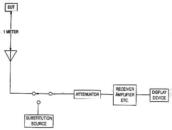
10.3.1.2 (U) Electric Radiation. -- See Figure 10-1 for a typical electric
radiated (ER) test setup.
a. (C) [Six lines redacted.]
UNCLASSIFIED
Figure 10-1. -- Typical Test Instrumentation for ER Tests (U) |
b. (U) Antenna Ground Planes. -- Whenever an unbalanced antenna (e.g., rod
antenna) is used. the ground plane upon which the EUT is placed shall be
extended to the base of the antenna and attached to the antenna base. A piece
of copper or brass with the same specifications as the bonding straps specified
in Paragraph 8.3 is acceptable for this purpose. Whenever a balanced antenna
(e.g., dipole antenna) is used, regardless of whether a balun is employed
or not, the detection system shall be grounded to the ground plane.
c. (C) [Five lines redacted.]
10.3.1.3 (U) Magnetic Radiation.
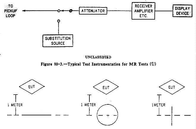
a. (U) Test Requirement. -- See Figure 10-3 for a typical magnetic radiation
(MR) test setup.
b. (C) [Four lines redacted.]
10.3.2 (C) [Two lines redacted.]
UNCLASSIFIED
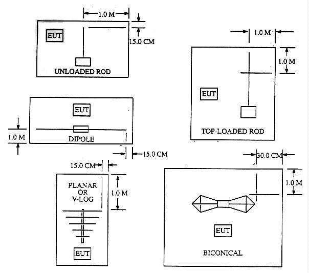
Figure 10-2.-Required Minimum Antenna Distances From Metal Surfaces and
Objects Other Than the EUT (U) |
10.3.2.1 (U) Line Conduction. -- General Requirements (includes guidance
for selection of lines to be tested).
a. (C) [Seven lines redacted.]
b. (C) [Three lines redacted.]
UNCLASSIFIED
Figure 10-4. -- Orientation of MR Pickup Loop (U) |
1. (U) [Two lines redacted.]
2. (U) [Two lines redacted.]
3. (U) [Two lines redacted.]
c. (C) [Twenty lines redacted.]
UNCLASSIFIED
Figure 10-6.-Typical Test Instrumentation for PLC Tests
(U) |
[Sixty-five lines redacted.]
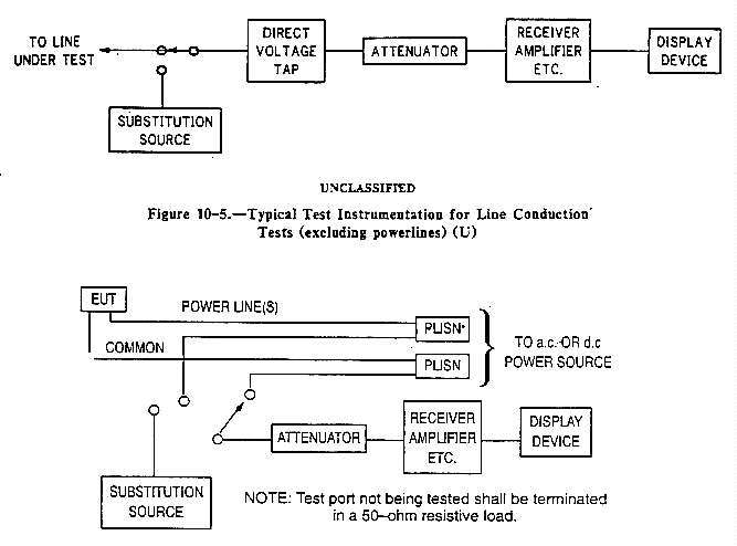
10.3.2.6 (U) Black Signal and Control Line Conduction. -- Black signal, control,
indicator and clock lines shall be examined. EUT lines that are not necessarily
terminated when in an actual operational setup need not be terminated when
tested. All other lines shall be terminated in their normal load impedance.
See Figure 10-5 for typical detection system setup.
10.3.3 (U) RED Line Emanations
10.3.3.1 (C) [Fifty lines redacted.]
_________________
[Footnote of five lines redacted.]
b. (U) The detection system shall be connected to the line under test in
such a fashion as to minimize the likelihood of producing distortion or
perturbations of the waveform on the line. In the lower test frequency ranges
where the 50 ohm detection system causes distortion of the waveform under
surveillance, high-impedance voltage probes, current probes, resistive-matching
networks, and high-pass filters may be used, provided the bandwidth and
sensitivity requirements are met and the transfer characteristics of the
probes are accurately known. Any correction or conversion factors associated
with such probes or pickup devices shall be applied to the measurement in
order to determine the voltage actually appearing on the line under test.
See Figure 10-5 for a typical detection system setup. All other requirements
specified for conduction tests are applicable.
10.3.3.7 (C) [Twenty-five lines redacted.]
_________________
[Classified footnote of two lines redacted.]
10.4. (US) Test Frequency Ranges and Bandwidths.
[Twenty-eight lines redacted.]
10.4.3 (U) Non-Tunable Frequency Coverage and Bandpass Requirements. --
Non-tunable frequency coverage and bandpass requirements are specified in
Table G-3. Note that for a.c. powerlines, the [two lines
redacted.]
FOR OFFICIAL USE ONLY
UNCLASSIFIED
[Pages 11-1 to 11-11]
CONFIDENTIAL
SECTION 11 -- EMANATIONS MEASUREMENTS
11.1. (U) Introduction. -- The measurement procedures herein are
applicable when measuring correlated emanations, peak EUT emanations, and
when separate signal and noise measurements are required. Emanations measurements
are required when performing emanations searches in each test media, using
tunable or non-tunable detection systems.
11.2. (C) General. -- [Six lines redacted.]
Deviation from this procedure is permitted only when an accurately pre-calibrated
device (e.g., antenna and associated matching device or probe) precedes the
point of signal substitution. When such devices are used all appropriate
conversion and correction factors shall be added to the substituted signal
level to obtain the level of the detected emanation When using a loop antenna,
the series injection measurement technique (injecting a calibrated current
into the loop) shall not be used if the detection system is equipped with
a beat frequency oscillator (BFO) or automatic gain control (AGC), all
measurements shall be made with the BFO1 and AGC turned off. An
attenuator shall be inserted in the detection system pickup line only when
the amplitude of the incoming interference signal is such that the detection
system input circuits are overdriven. The attenuator shall have a characteristic
impedance of 50 ohms (+/-3 ohms) over the test frequency range in which it
is employed. Care shall be taken to ensure that accessory equipment (EUT
exerciser equipment, oscilloscopes. earphones, etc.) and test setup ground
loops do not affect measurement accuracy.
11.3. (U) Measurement Accuracy. -- All measurements made in accordance
with this document shall have the following accuracies:
a. (U) Frequency accuracy: +/- 5%
b. (U) Amplitude accuracy:
+/-2dB for fc < 1 GHz
+/-4 dB for fc > 1 GHz
11.4 (U) Emanations Measurement Procedures.
11.4.1 (U) Correlated and Peak EUT Emanations.
11.4.1.1 (C) [Four lines redacted.]
11.4.1.2 (C) [Four lines redacted.]
11.4.2 (C) [Two lines redacted.]
[Full-page redacted.]
[Figure redacted.]
CONFIDENTIAL
Figure 11-1. -- Examples of Signals to be Measured, Method 1 (U) |
[Figure redacted.]
CONFIDENTIAL
Figure 11-2. -- Examples of Signals to be Measured, Method 2 (U) |
11.4.2.3 (C) [Three-quarter-page redacted.]
11.4.3 (U) Application of Measurement Methods. -- The following paragraphs
address the application of the measurement methods, described in Paragraph
11.4.2, for measuring emanation and noise levels during searches performed
in accordance with Chapter 10.
11.4.3.1 (U) ER, MR and BLC Measurements. -- The following measurement methods
apply when performing ER, MR, and BLC emanation searches.
a. (C) [Five lines redacted.]
[Figure redacted.]
CONFIDENTIAL
Figure 11-3. -- Examples of Signals to be Measured, Method 3 (U) |
[Figure redacted.]
CONFIDENTIAL
Figure 11-4. -- Positive/Negative Signal Examples (U) |
[Three lines redacted.]
b. (C) [Ten lines redacted.]
11.4.3.2 (C) [Four lines redacted.]
11.4.3.3 (U) RED Line Emanations Measurements. -- The following procedures
apply when measuring RED analog or RED digital signal energy spectrum on
RED lines. The measurements are performed using a tunable detection system
with or without a Demodulator.
a. (U) RED Analog Signal Energy Spectrum Measurements.
(1) (U) With demodulator. -- The procedure outlined in Paragraph 11.4.3.l.a
shall apply.
(2) (U) Without demodulator. -- The procedure outlined in Paragraph 11.4.3.1.b
shall apply.
b. (U) RED Digital Signal Energy Spectrum Measurements.
(1) (U) With Demodulator. -- The recommended method is Method 3 (IG). The
resultant measurement using Method 3, plus any appropriate conversion and
correction factors, is equal to the level of the signal energy of the RED
digital signal(s) at that particular test frequency. As an alternative, Method
1 (first choice) or Method 2 (second choice; using crest/trough method at
d.c. post-detection outputs) may be used. The resultant measurement, using
Method 1 or 2, minus the impulse bandwidth factor {20 log10
[IBW(MHz)]}, plus any appropriate conversion and correction factors, is equal
to the level of the signal energy of the RED digital signal(s) at that particular
test frequency.
(2) (U) Without Demodulator. -- The recommended method is Method 3 (IG).
The direct method is recommended in lieu of the crest/trough method. The
resultant measurement, using Method 3, plus any appropriate conversion and
correction factors, is equal to the level of the signal energy of the RED
digital signal(s) at that particular test frequency. As an alternative, Method
2 may be used. The direct method is recommended in lieu of the crest/trough
method. The resultant measurement, using Method 9, minus the impulse bandwidth
factor {20 log10 [IBW(MHz)]}, plus any appropriate conversion
and correction factors, is the level of the signal energy of the RED digital
signal(s) at that particular test frequency.
11.5. (U) Signal and Noise Measurements.
11.5.1 (U) General. -- When correlated emanations are detected, and analysis
is required, both signal and noise measurements of the detected output shall
also be performed and documented. The minimum number of signal and noise
measurements required for detected CORR E is three per decade. If more than
three per decade are found, the three worst-case (i.e., highest observed
signal-to-noise ratio) emanations shall be measured. The intent is to measure
characteristics related to the correlation component of the detected emanation.
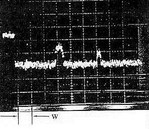
Figure 11-5 shows a correlated emanation in the presence of equipment ambient.
An appropriate measurement window, W, is shown for this correlated emanation.
The objective is to select W such that noise not contributing to the
TEMPEST-limited ambient is ignored in proximity to the correlated emanation.
All signal and noise measurements are made within W. The noise measurement
made in W is the TEMPEST-limited ambient. When performing peak EUT emanation
measurements (Paragraph 11.4.1.2), use the measurement window defined in
Appendix E, Paragraph 3.4. Noise measurements shall be made using either
a statistical signal analyzer (or equivalent measurement system) that measures
the mean and variance of the sampled video voltage; or a visual "A-scope"
presentation.
UNCLASSIFIED
Figure 11-5. -- Example of Noise Measurement Window, W (U) |
11.5.2 (U) Procedure 1: Statistical Measurements. -- Using this procedure,
the voltage parameters of the detected emanation to be measured and documented
are the peak signal mean (Sp) and the rms noise (No).
It may be necessary to document sets of signal and noise measurements
corresponding to the test pattern used (e.g., test patterns A, B, or C for
parallel processed digital signals, discussed in Appendix C).
11.5.3 (U) Procedure 2: Visual ''A-scope'' Measurements. -- Using this procedure,
the voltage parameters of the detected emanation to be measured are the peak
signal mean (Sp) (maximum polarity for bi-polar signals) and the
peak-to-peak noise (Npp). All measurements shall be performed
using the "A-scope" presentation. The following paragraphs discuss examples
illustrating the visual "A-scope" measurements for serial (analog or digital)
and parallel (digital) signal processing.
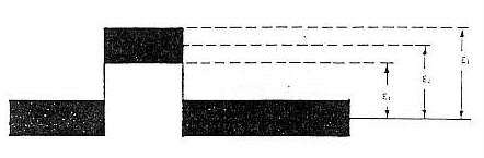
l l .5.3.1 (U) Serial Signals. -- Figure 11-6 illustrates an ideal emanation
related to a signal serially processed. The output levels (i.e., voltage
or vertical divisions) to be measured are E1, E2, and
E3.
a. (U) The noise measurement is equal to:
N = E3 - E1
Note: The intent is to measure the noise that occurs with the signal.
A simpler method may be used when it is obvious that the baseline noise appears
equal to the noise on the signal. In this case, it is acceptable to measure
the baseline noise.
b. (U) The signal measurement is equal to: Sp = E2
UNCLASSIFIED
Figure 11-6. -- Signal/Noise Measurements: Serial Signal Example (U) |
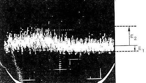
11.5.3.2 (U) Small Signal-to-Noise Ratios. -- When correlated emanations
are characterized by small signal-to-noise ratios, performing separate signal
and noise measurements may be difficult. An alternate procedure may be used
which requires a visual measurement representing'the signal plus noise, and
a visual measurement representing the noise alone. Figure 11-7 illustrates
this type of emanation (ideal). The voltage levels to be measured are
E1 and E2.
a. (U) The noise measurement is equal to:
Npp = E2 - E1
b. (U) The signal plus noise measurement is equal to:
S + Np = E2
c. (U) The signal level is computed using the following equation:
S = E2 - Npp/2 = (E2 + E1) / 2
Note: As in previous noise measurements, the baseline noise
(Npp) may used when it is obvious that it appears equal to the
noise on the signal. This procedure can be extended to apply to emanations
related to a signal that is either serially or parallel-processed.
11.5.3.3 (U) Extensions/Precautions. -- The previous examples illustrate
the signal and noise measurement parameters to be measured using simplified
signals. While it is recognized that many signals encountered in TEMPEST
testing do not appear in this form, the concept remains the same and the
measurement procedure should be easily extended. The noise voltage measurements
shall relate only to the noise that limits detectability of the signal; the
limiting noise is not necessarily the maximum noise level (e.g., do
not measure 60 Hz powerline noise that is present but does not limit
detectability of the signal).
11.5.4 (U) Relating Statistical and Visual Measurements. -- The statistical
and visual measurements outlined in Paragraphs 11.5.2 and 11.5.3 are not
precisely related because of the subjective nature of the visual measurements.
However, based on simplifying assumptions2, the statistical ard visual noise
measurements can be related by:
Npp (db) = No (db) / 14 db
_____________________
2 The 14 dB factor is based on the assumption that Npp
= (2)(2.58) No. This is discussed in Appendix B of NACSIM
5002.
UNCLASSIFIED
Figure 11-7. -- Small Signal-to-Noise Ratios Example (U) |
UNCLASSIFIED
[Page 11-12]
THIS PAGE IS INTENTIONALLY BLANK
[Pages 12-1 and 12-2]
CONFIDENTIAL
SECTION 12 -- LIMITS
12.1. (U) General.
12.1.1 (U) Compromising emanations limits (curves and tabulated breakpoints)
are contained in Appendix H (Level I), Appendix I (Level II), and Appendix
J (Level III).
[Sixteen lines redacted.]
12.2. (U) Electromagnetic Radiation Limits.
12.2.1 (U) Electric Radiation Limits. -- The electric radiation limits apply
to tests performed with an E-field antenna located one meter from the EUT.
One meter from the EUT is the standard measurement point.
12.2.2 (U) Magnetic Radiation Limits. -- The magnetic radiation limits apply
to tests performed with an H-field antenna with the center of the loop located
one meter from the EUT. (No MR tests are required for category I or J; therefore,
there are no limits for these categories.)
12.3. (U) BLACK Line Limits.
12.3.1 (C) BLACK Line Conduction Limits. -- [Twenty-two
lines redacted.]
CONFIDENTIAL
This ends the main body text. Appendixes A-M follow.
Appendix A:
nstissam1-92a.htm
Transcription and HTML by Cryptome.