Overview
Older versions of the Qualcomm OmniTRACS satellite fleet tracking system are starting to show up at ham fests. These units include a very nice one watt RF power amplifier for 14.0-14.5 GHz range, and a low-noise 11.7-12.2 GHz receive circuit, but we're still trying to figure those sections out! In the mean time, we'll show you a project to utilize the OmniTRACS' main 10 MHz Temperature Compensated Crystal Oscillator (TCXO) as a time standard for your workbench.
The 10 MHz TCXO is model number T424 and made by EG&G Frequency Products, Inc. And yes, EG&G is one of the large defense contractors which works out at Area 51. The stock oscillator unit measured only a few Hertz off of 10 MHz, and the unit has an externally accessible trimmer capacitor which you can use to "zero beat" the oscillator directly to WWV. This will allow you to tune the oscillator to within 1 Hertz of the 10 MHz WWV NIST time standard.
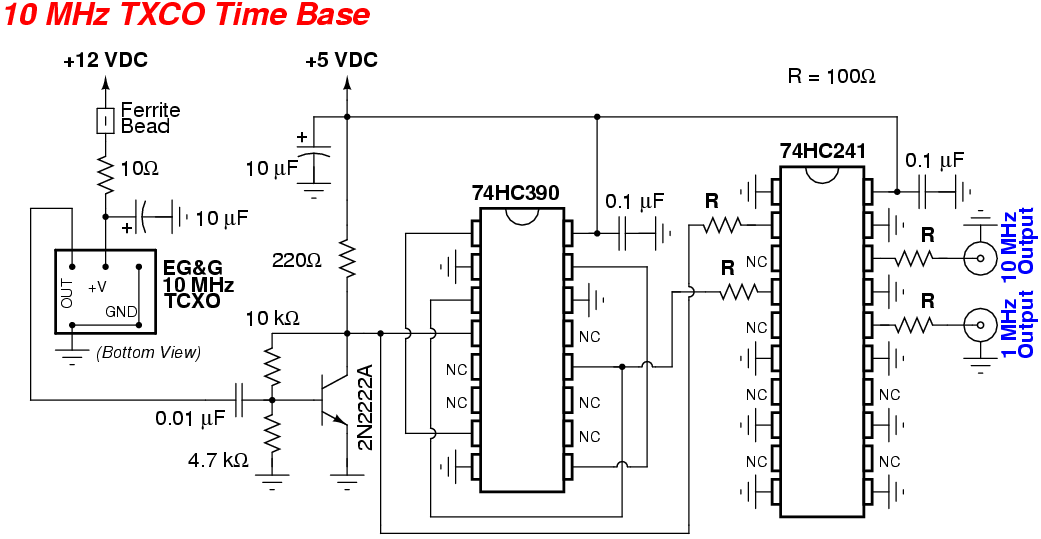
The 10 MHz output signal of the TCXO will be buffered with a simple 2N2222A transistor and sent to a 74HC390 dual-decade ripple counter to be divided down for generating an optional 1 MHz reference signal. The final two signal outputs are isolated with a 74HC241 octal 3-state buffer. The signals are then routed to front-panel BNC jacks. A few series 100 ohm resistors limit the current in case any of the outputs get shorted.
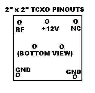
EG&G TCXO Pinout
Pictures & Construction Notes
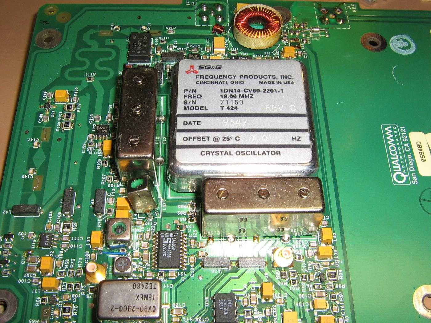
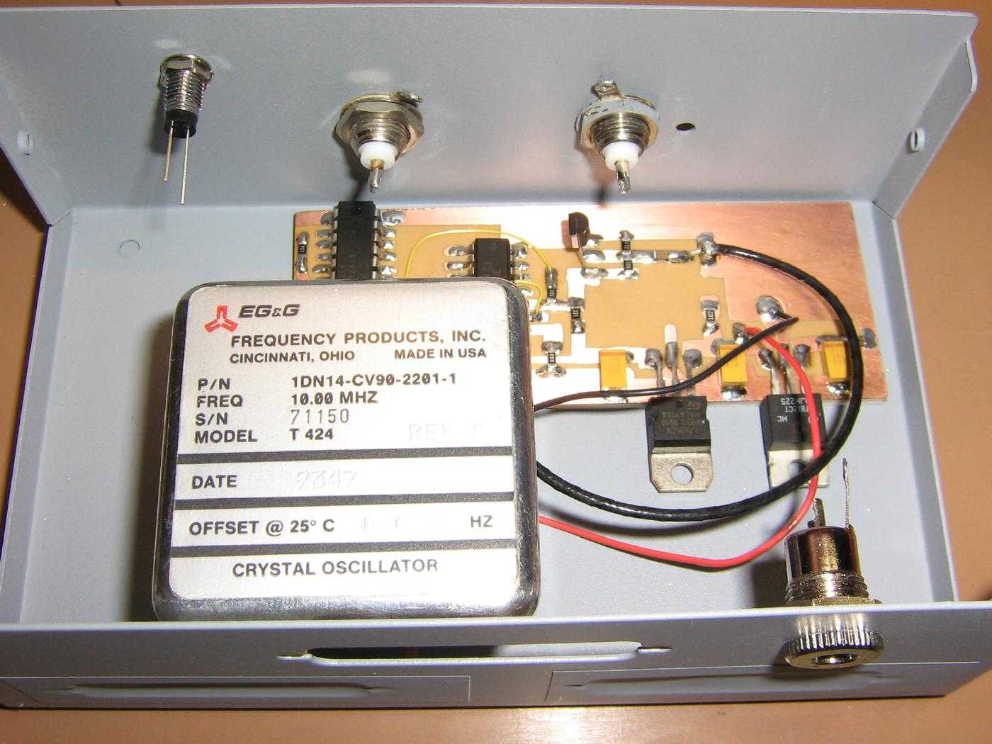
EG&G 10 MHz TCXO installed in a stock Qualcomm OmniTRACS unit.
The oscillator's label reads:
EG&G FREQUENCY PRODUCTS, INC.
CINCINNATI, OHIO   MADE IN USA

P/N    1DN14-CV90-2201-1
FREQ   10.00 MHZ
S/N    71150
MODEL  T 424    REV C

DATE   9347

OFFSET @ 25°C   0.0 HZ
Remove the TCXO by heating the bottom of the circuit board with a hot air gun and gently prying around the TCXO's case.
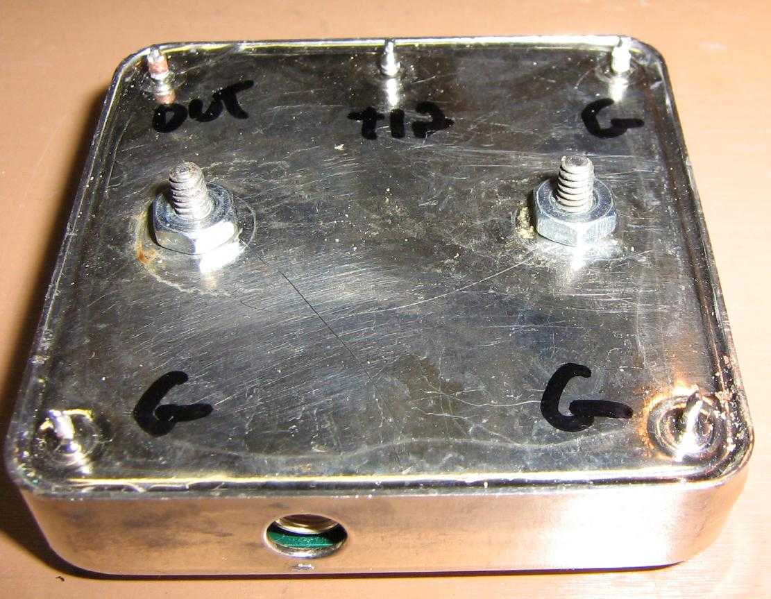
Bottom view of the TCXO.
Only three connections are needed: +12 VDC, 10 MHz output, and ground.
Note the access hole for the trimmer capacitor (on the bottom). This is for slighly tweaking the output frequency of the TCXO.
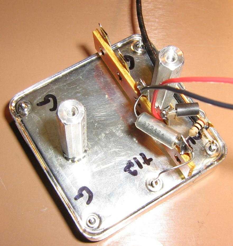
TCXO support components attached to a terminal strip.
Using the threaded studs on the bottom of the TCXO, add two standoffs for mounting the oscillator in a position which allows you to access the trimmer capacitor.
The 10 MHz output of the oscillator is routed via a piece of small-diameter coaxial cable.
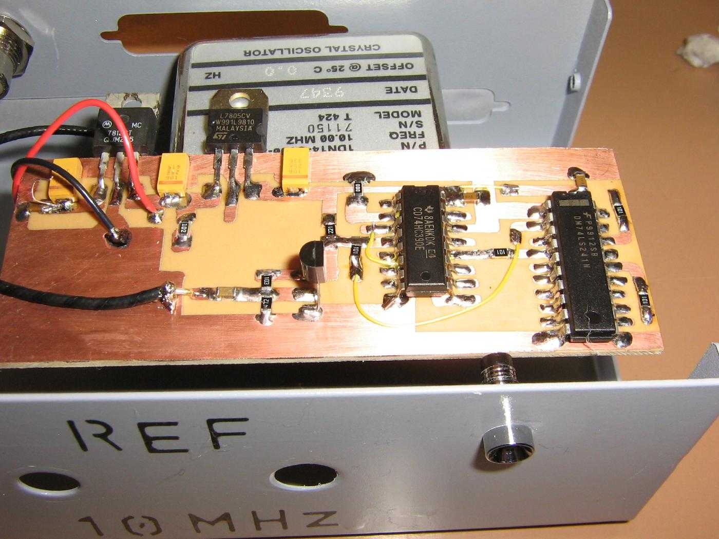
The oscillator's voltage regulator, buffer, and divider circuit board will be mounted in an old printer switch case.
The oscillator's RF output comes into the 2N2222A via the coaxlal cable on the lower-left.
There is no real need to make the PC board overly complicated, but try to utilize proper ground plane construction.
The LM7812 (for +12 VDC) and LM7805 (for +5 VDC) voltage regulators are on the upper-left.
This device was meant to be powered from an external voltage source of around +15 VDC. You may wish to use low-dropout voltage regulators if you use a +13.8 VDC power supply.
Mounting the oscillator and circuit board.
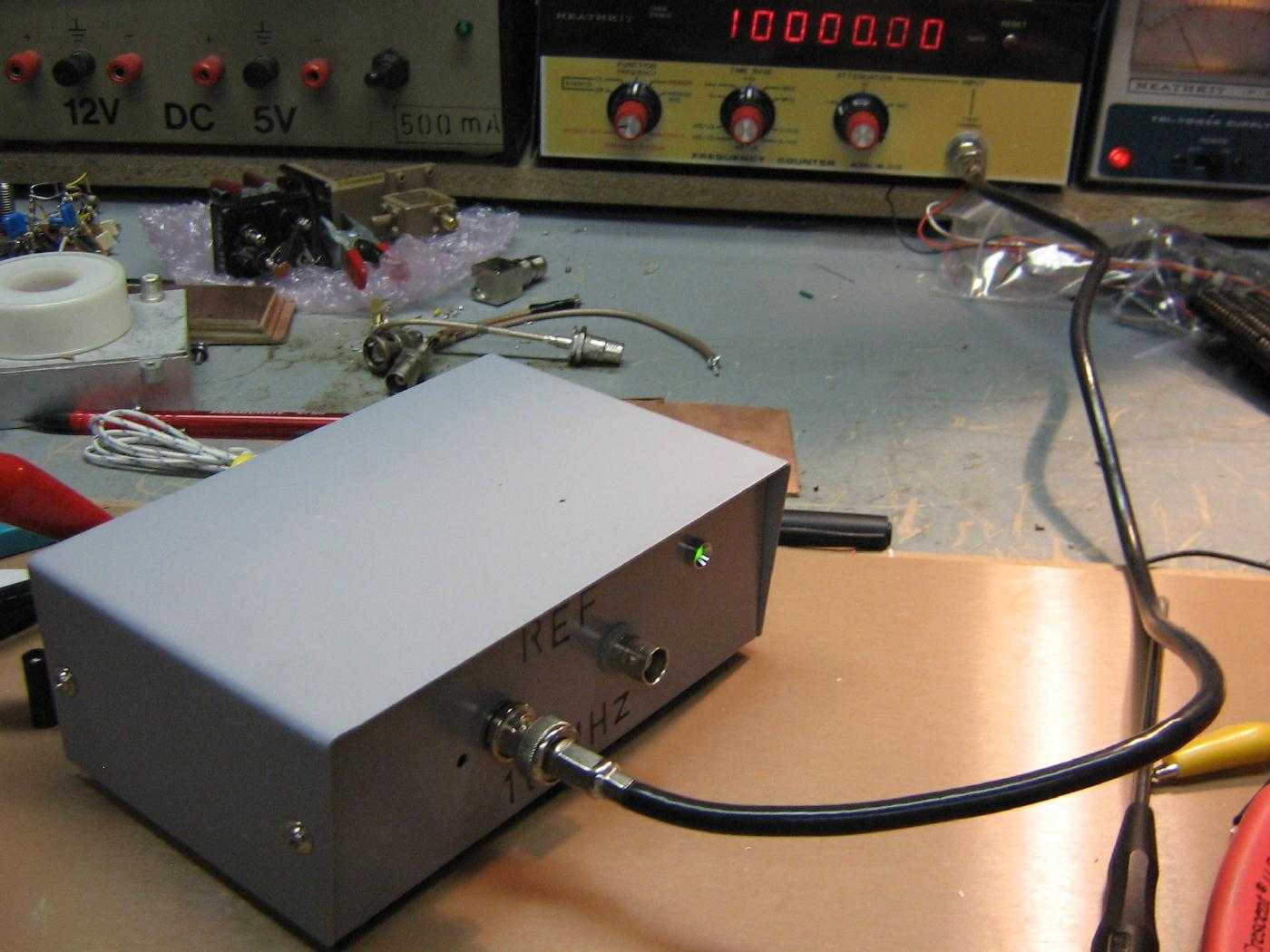
The front-panel has a LED power indicator and two BNC jacks for the 10 MHz and 1 MHz outputs.
On the rear-panel (right) is the incoming DC power jack.
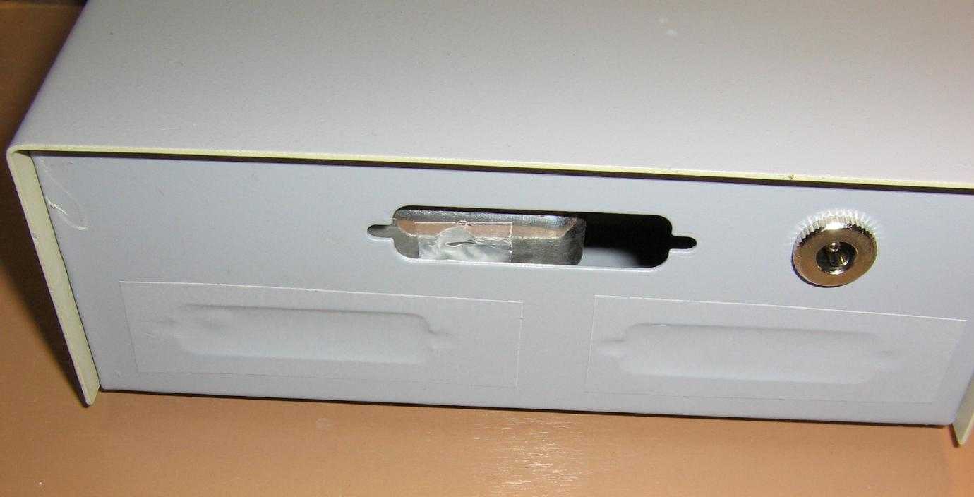
Note how the oscillator was mounted so an existing hole in the case allows access to the frequency adjustment trimmer capacitor.
A small piece of aluminum duct tape covers the access hole.
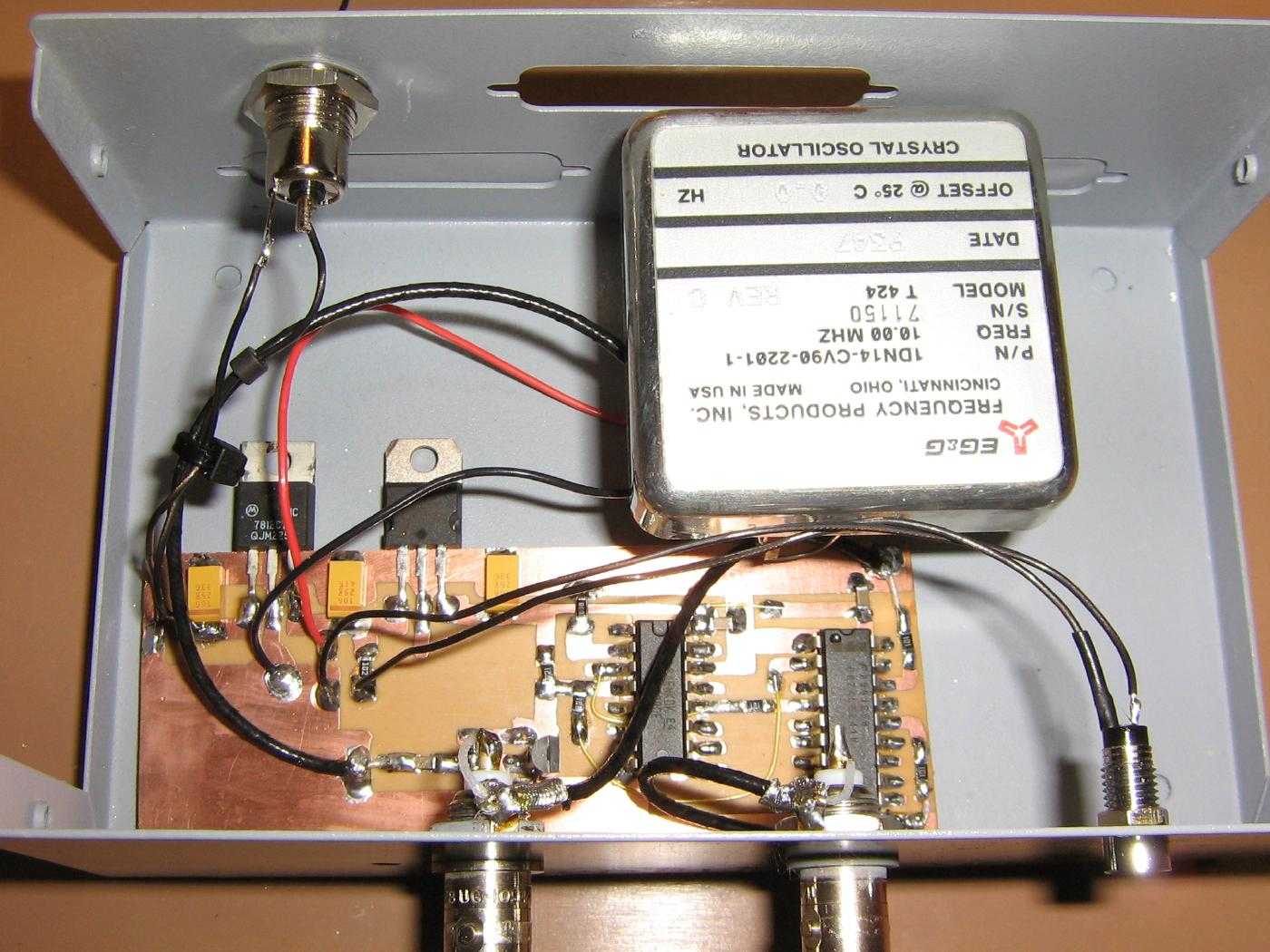
Alternate view with the completed wiring.
Try to use coaxial cables for all the lines carrying the 10 MHz or 1 MHz signals.
The front-panel BNC connector on the left is the 10 MHz output, the other is the 1 MHz output.
To zero-beat the oscillator, tune a shortwave receiver (AM) to the 10 MHz WWV time standard. Be sure to use a quality antenna as the received signal will need to be quite strong.
Next, connect a short little rubber duck antenna to your powered time base and position the shortwave receiver so you are receiving both signals at once. You may have to place the shortwave receiver in another room if the WWV signal was overpowered by the time base signal.
You should be hearing a "Whoosh-Whoosh-Woosh" sound as both the time base signal and the WWV carrier are heterodyned together. The number of "whooshes-per-second" is equal to the frequency, in Hertz, that your time base is off. The WWV RF carrier is guaranteed to be exactly 10 MHz, so it'll be your time base that's off, not WWV.
You'll now want to let everything warm up for a period of a hour or so. After the time base is at its proper operating temperature, slowly tweak the trimmer capacitor with a non-conductive tool until the number of "whooshes" gets down to around one per second. If the number of "whooshes" goes up, turn the capacitor in the other direction. You can tweak the oscillator's final frequency even further, but it'll just end up driving you crazy.
That's it! Your 10 MHz time base should now within one or two Hertz of exactly 10 MHz!
You can now use your new time base for calibrating a frequency counter, or to replace the reference oscillator in your PRO-2006 scanner...
Schematics
Notes / Datasheets
- 74HC390 Dual-Decade Ripple Counter (51k PDF)
- 74HC241 Octal Buffer/Line Driver (55k PDF)
- Zero-Beating to WWV Audio (622k MP3)
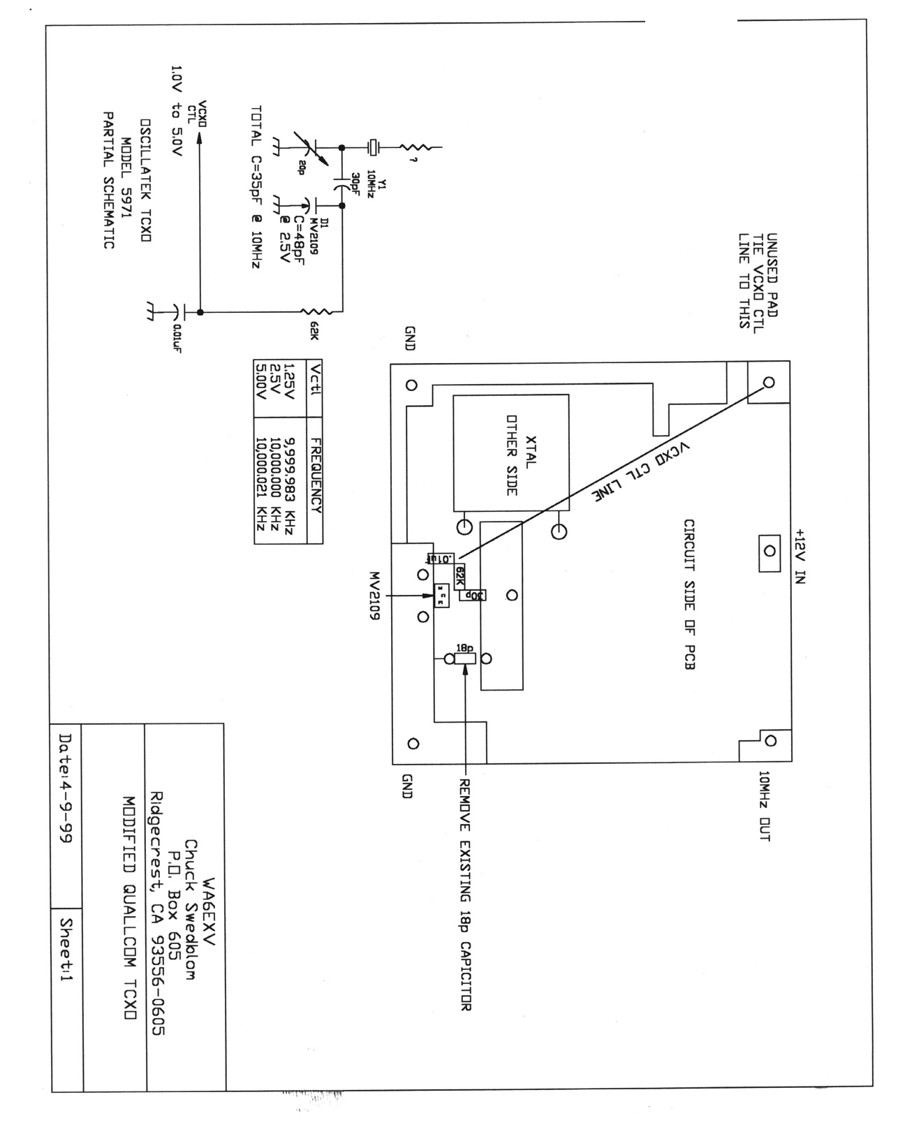
- Qualcomm TCXO Pinouts and Modifications
- Oscilloscope View of the Qualcomm 10 MHz TCXO Output Signal Around 500 mV peak. (External Voltage Control)
- Low Phase Noise Design: Isolation Amplifiers
- A New 5 and 10 MHz High-Isolation Distribution Amplifier (241k PDF)
- Origin of 1/f PM and AM Noise in Bipolar Junction Transistor Amplifiers (946k PDF)
- MtronPTI XO5051 Series OCXO Oscillators (118k PDF)