A return loss bridge is a wideband resistive bridge network which can be used to verify the impedance of coaxial cables, antennas, tuning stubs, filters, etc. It works by comparing an "unknown" impedance to a "known" impedance, which is usually 50 ohms in radio work. A DC voltage signal is generated which corresponds to the level of impedance mismatch between the "known" and "unknown" impedances. Generally, the higher the DC voltage output, the worst the impedance mismatch is. Return loss bridges are ideal for checking antenna systems as they are simple to build and have a very large RF bandwidth. The version documented here should be accurate from below 1 MHz to over 500 MHz. The common Standing Wave Ratio (SWR) meter which is normally used to verify an antenna system has a very narrow RF bandwidth, usually only accurately covering 50 MHz or so at a time.
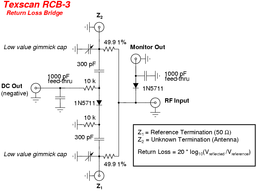
From a Texscan RCB-3 Manual:
Return loss (reflection coefficient) bridges are broadband RF comparators. These devices develop a DC potential with respect to ground which is proportional to the degree of unbalance in the arms of the bridge circuit. The bridges provide DC isolation to prevent undesired loading of the circuitry by associated test equipment.
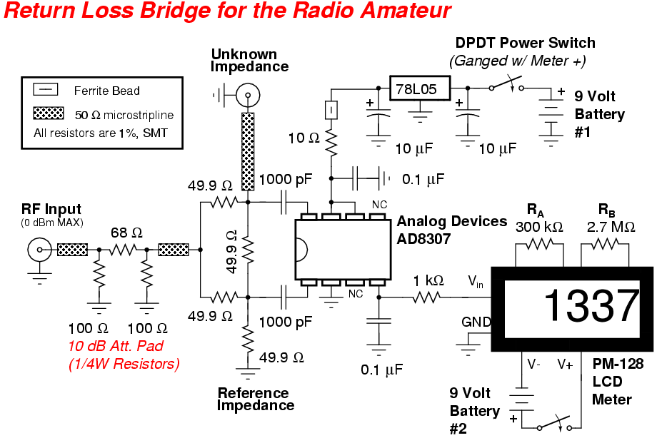
This particular return loss bridge will be based around an Analog Devices AD8307 logarithmic amplifier. It is designed to work from DC to over 500 MHz, and has a resolution of 92 dB. The AD8307 is a perfect choice for this project, as the AD8307's +INPUT and -INPUT differential inputs will do the majority of the work for us. The RF input will be split between these two ports using a simple resistive divider network, and any "unbalance" in the divider (when compared to 50 ohms) will be detected, amplified, and output by the AD8307. The AD8307 will output a DC voltage level between around 200 millivolts and 1.5 volts. This signal is then fed to a common PM-128 LCD voltage meter. The PM-128 is a very common display which is both low-cost (under $10) and easily available from places like JDR Microdevices (www.jdr.com). The PM-128 LCD meter will need to be slightly modified to display a maximum of 2 volts. In its stock configuration, it can only display up to 200 millivolts. The modification involves adding two divider resistors, RA and RB. Resistor RA should be changed to 300 kohms and resistor RB should be changed to 2.7 megaohms. Try to use 1% metal-film resistors if you can. Also, the PM-128 LCD meter requires a separate 9 volt battery power supply, as the PM-128 needs to be isolated from the voltage source it is monitoring. A Dual-Pole, Dual-Throw (DPDT) power switch will be used to turn both the LCD meter and the return loss bridge on and off.
You'll need a tuneable RF signal generator and several common attenuator pads to operate the return loss bridge. For this FM radio example, we'll use a Broadcast Warehouse PLL+ 1 watt exciter as the signal source and a commercial 60 dB attenuator. The 60 dB of attenuation may seem like alot, knocking the 1 watt (+30 dBm) exciter RF signal down to a measly -30 dBm. But remember, the AD8307 logarithmic amplifier is a very sensitive device. Going overboard on attenuation (to a point) won't hurt the final readings. In fact, you'll want the final RF input signal to the return loss bridge to be under 1 milliwatt (0 dBm). The return loss bridge has an additional internal 10 dB of attenuation.
Operating the return loss bridge will go something like this:
- Turn on the power to the return loss bridge. Note the baseline reading on the LCD meter. It should be reading around 230. Ignore any decimal points for these readings.
- Connect the RF signal source, tuned to the desired frequency for the antenna to be evaluated, to the RF Input jack of the return loss bridge. Be sure it is well attenuated to under 1 milliwatt (0 dBm).
- Leave the Unknown Impedance jack open.
- Note the LCD meter reading. This will be your worst-case impedance mismatch value.
- Connect a pure resistive 50 ohm load to the Unknown Impedance jack.
- Note the LCD meter reading. This will be your best-case impedance match value.
- Remove the 50 ohm load from the Unknown Impedance jack and connect your antenna using a short length of low-loss coaxial cable. Be sure your antenna is isolated from any metal objects and from the RF signal source.
- Note the LCD meter reading. You'll want to then tune the antenna until this value is near that of the best-case impedance match value. It will never be perfect, so don't spend all day doing it.
You may want to make up a set of 75 ohm, 100 ohm, 150 ohm, and 300 ohm resistive loads using standard 1/4 watt carbon-film resistors and some old RF connectors. If you connect these to the Unknown Impedance jack during the tune-up phase, you can then get a baseline reading of SWR ratios 1.5:1, 2:1, 3:1, and 6:1, respectively. Try to get your antenna's final SWR value below a ratio of 3:1.
Refer the The ARRL Handbook for Radio Amateurs for more detailed information on tuning and testing radio antennas.
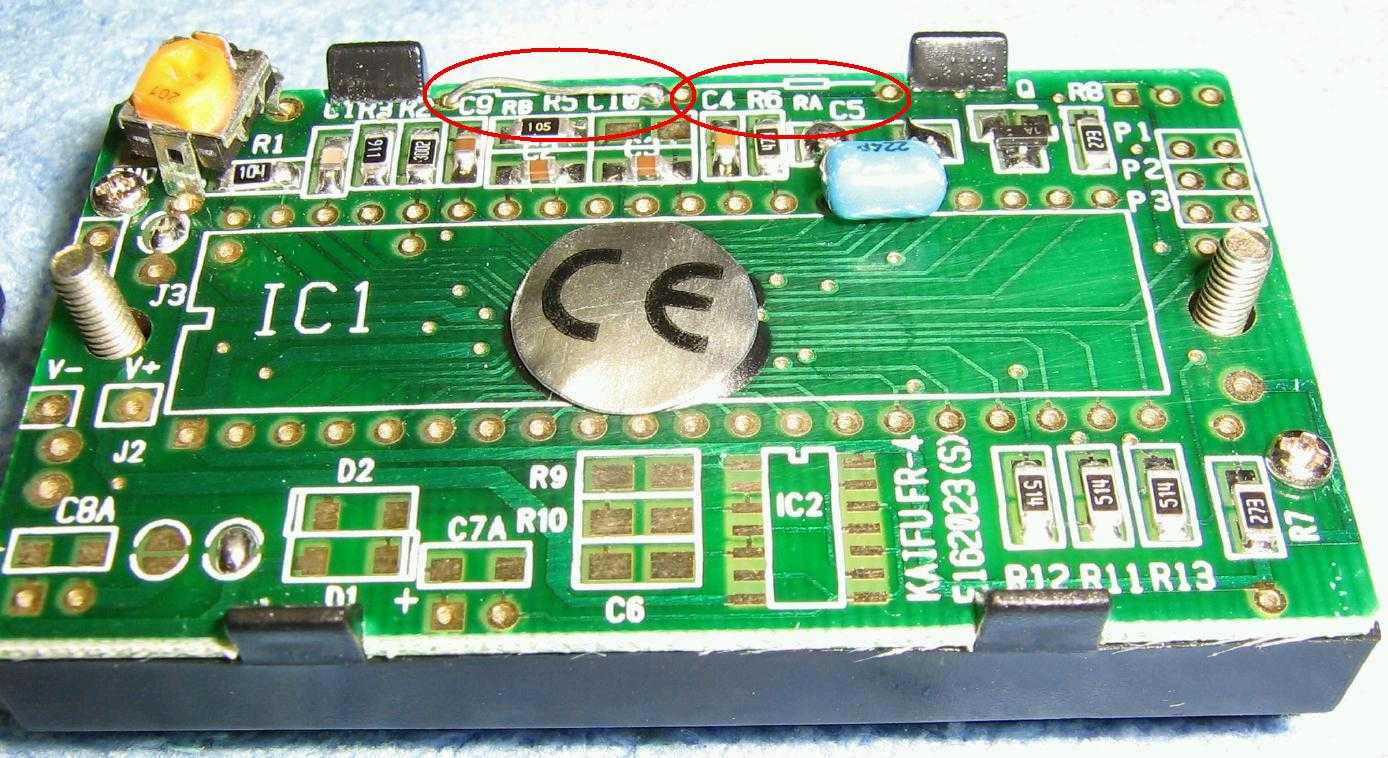
Rear view of a stock PM-128 LCD digital voltage meter. RA is open and RB is a wire jumper. The decimal place pads (P1, P2, P3) on the right are all open.
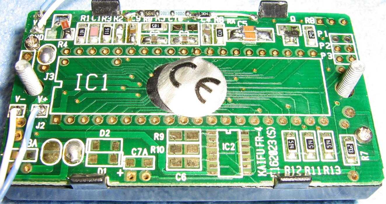
Rear view of a modified PM-128 LCD digital voltage meter, as used in this project. Resistor RA is changed to 300 kohms and resistor RB is changed to 2.7 megaohms. Several series surface-mount resistors where used to make the 2.7 megaohm resistor. Also, the potentiometer was removed and replaced with a 165 ohm resistor and the large, blue 0.22 µF capacitor was replaced with two surface-mount 0.1 µF capacitors in parallel. Leave the decimal place pads open.
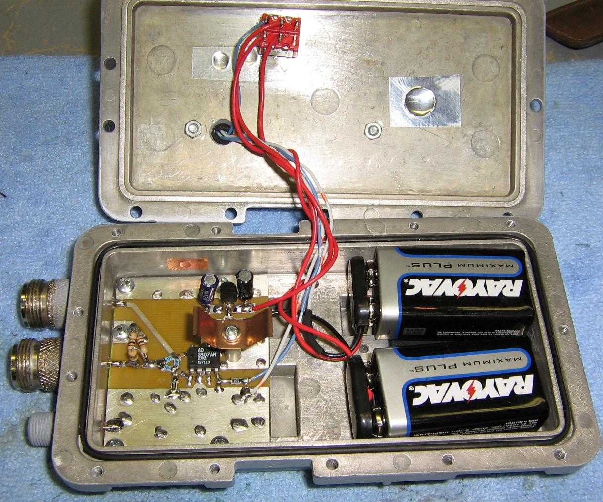
Internal overview. It's built into an old California Amplifier MMDS downconverter case. The middle N-connector is the RF Input and the top N-connector is the Unknown Impedance (antenna) connection. The two batteries power the return loss bridge circuit and the PM-128 meter.
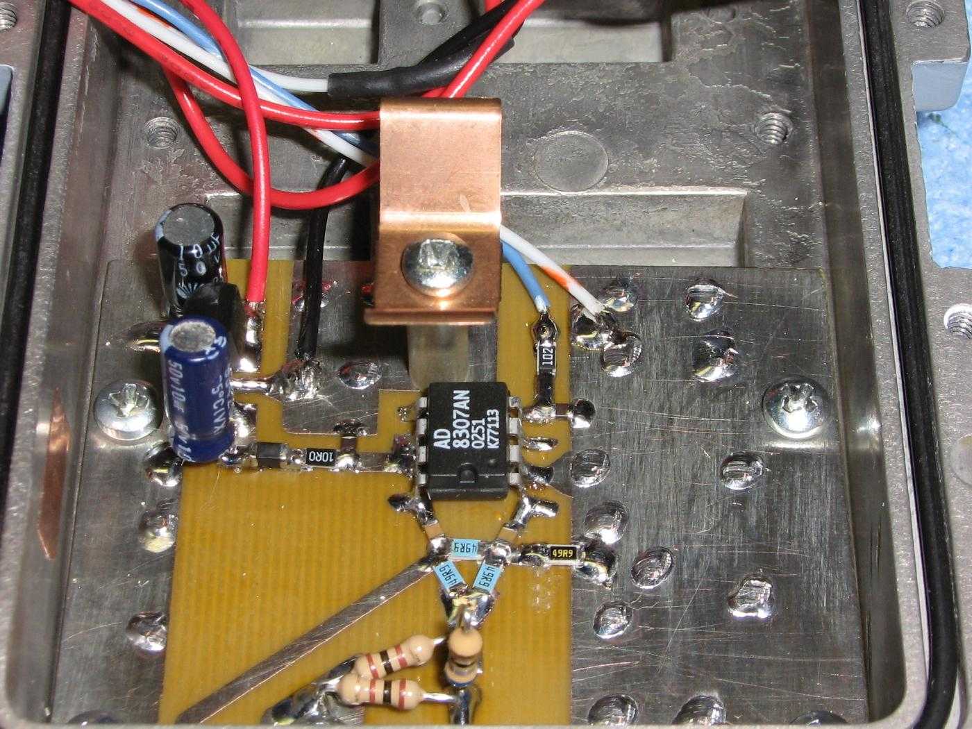
Close up view of the RF Input (bottom), the input 10 dB attenuator pad, the resistive bridge made up of 1% tolerance 49.9 ohm resistors, and the AD8307 logarithmic amplifier. The 78L05 voltage regulator and filter capacitors are to the left. Be sure your PC board is constructed with a good RF ground plane.
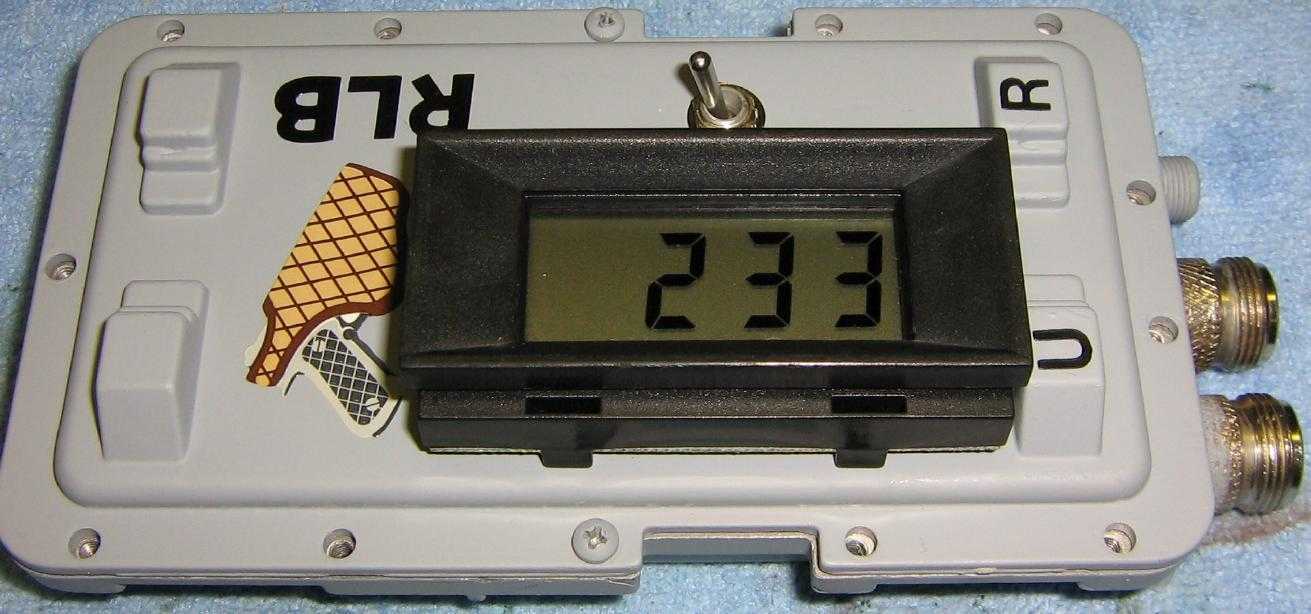
Outside case overview. Baseline reading on the meter. Yes, it is upside down. So?

Test setup. The RF signal source is a Broadcast Warehouse PLL+ 1 watt exciter running through a single 60 dB attenuator. Several different value resistive loads are shown on the right.
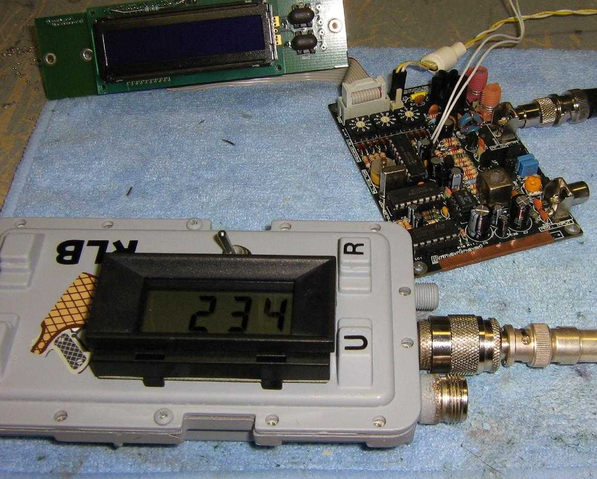
Test setup, baseline reading. The Unknown Impedance jack is left open and there is no RF signal input.
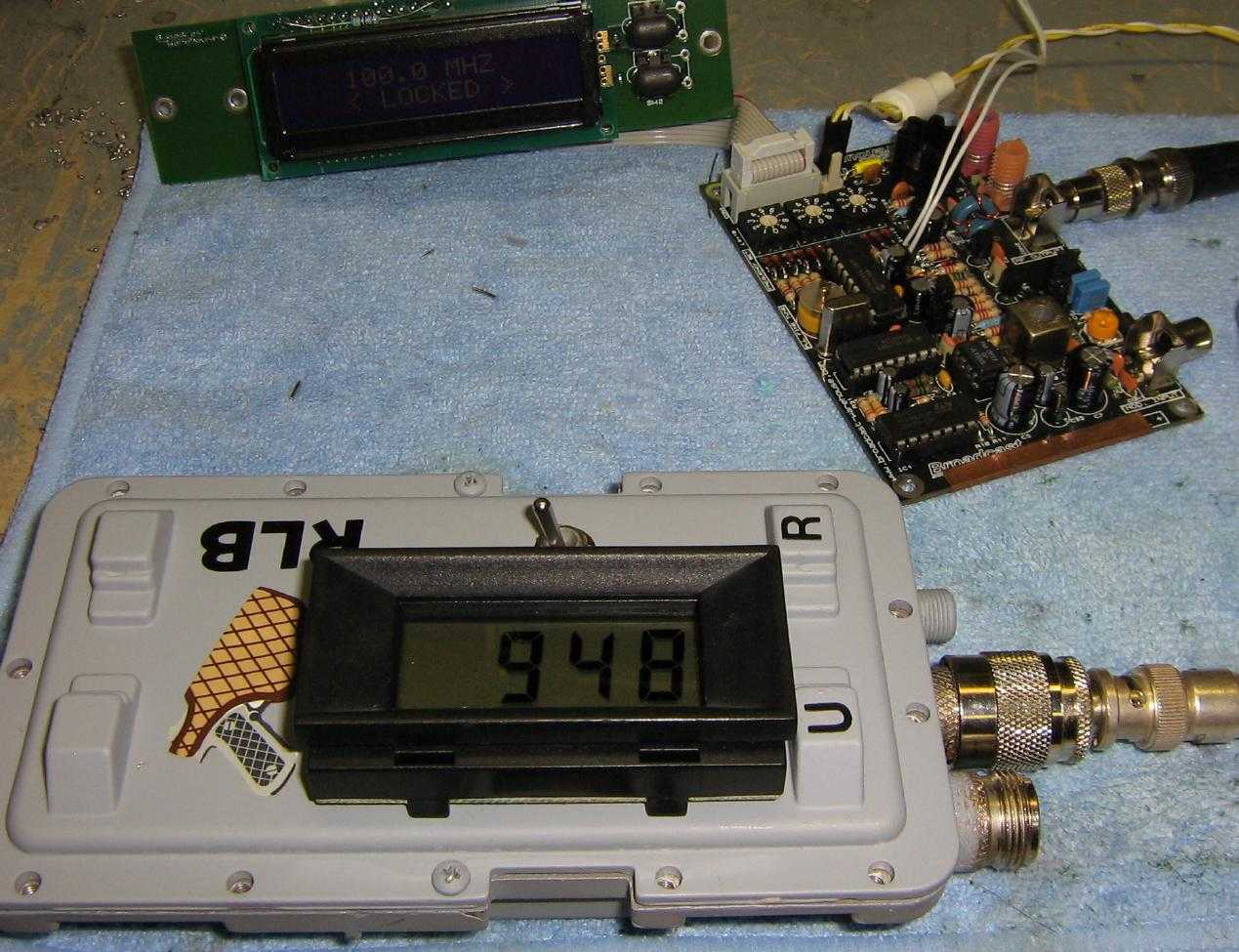
Test setup, worst-case reading. The 100 MHz RF signal source is now operating and the Unknown Impedance jack is left open.
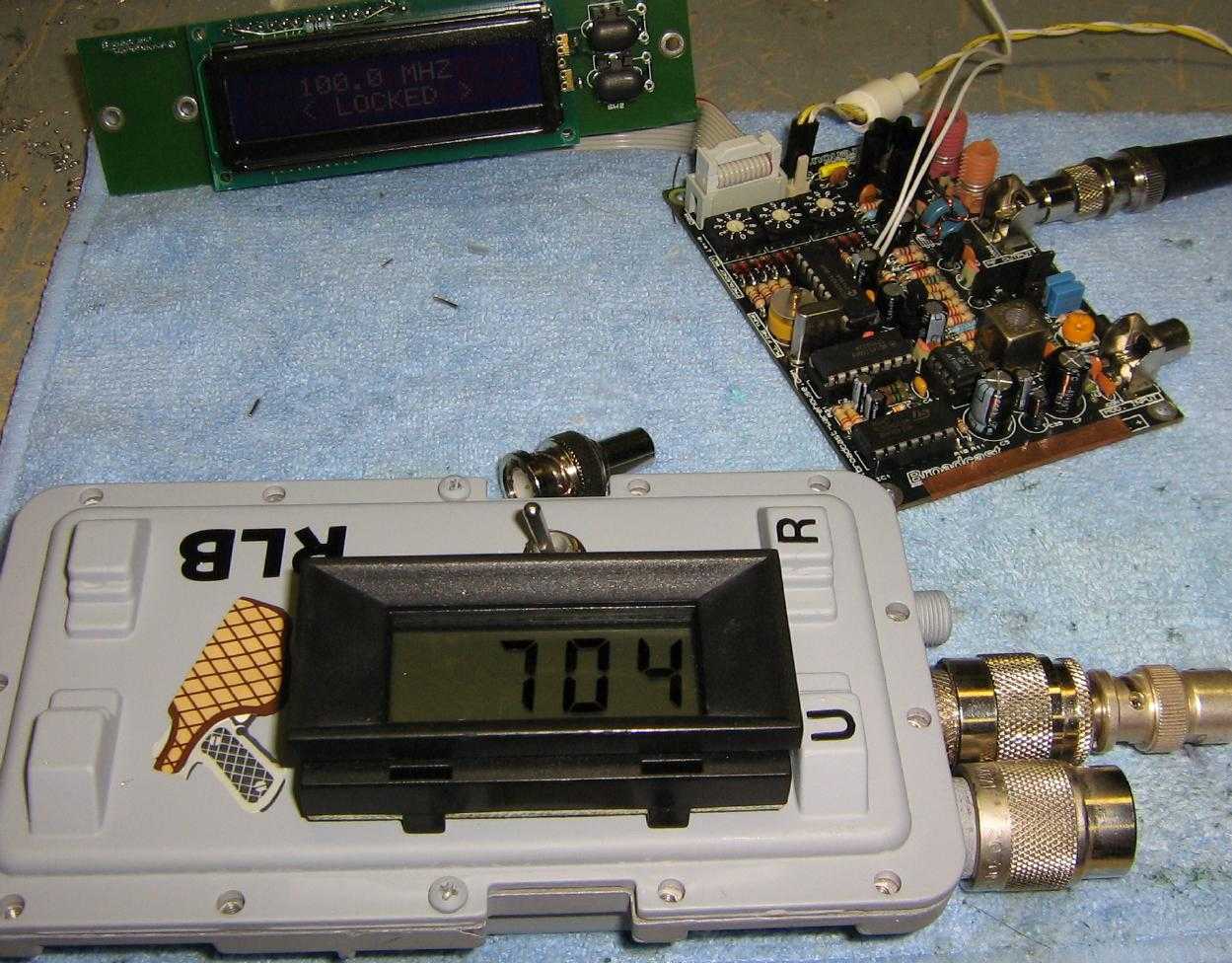
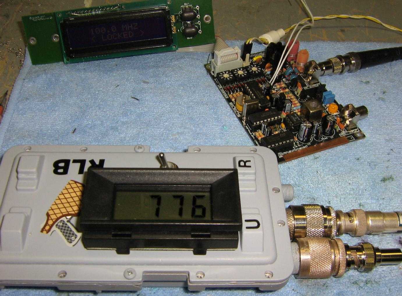
Test setup, best-case reading. The Unknown Impedance jack is connected to a pure resistive 50 ohm load.
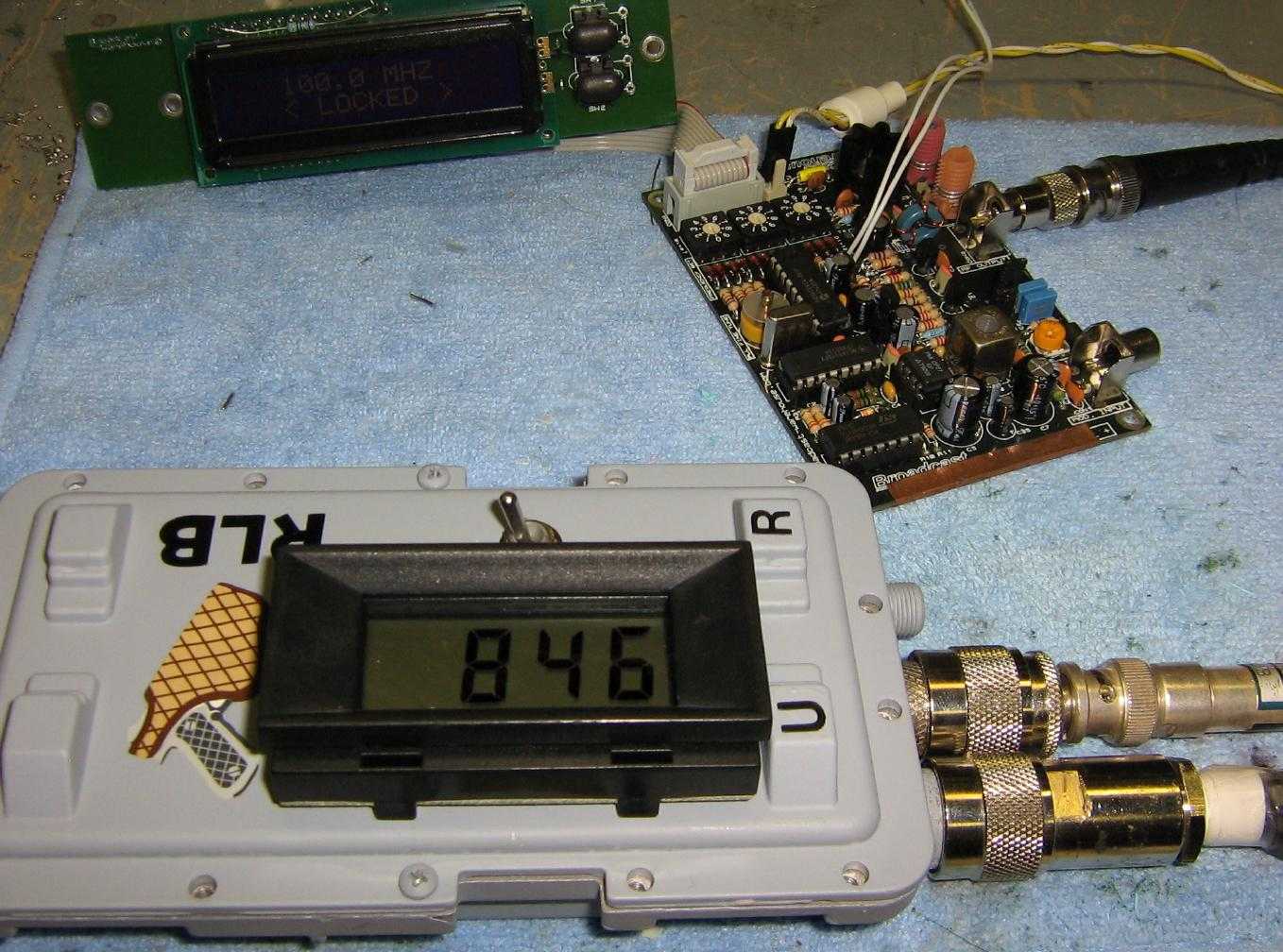
Test setup, 1.5:1 SWR reading. The Unknown Impedance jack is connected to a pure resistive 75 ohm load.
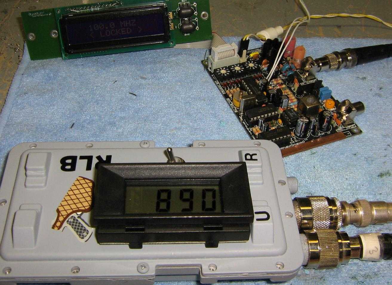
Test setup, 2:1 SWR reading. The Unknown Impedance jack is connected to a pure resistive 100 ohm load.
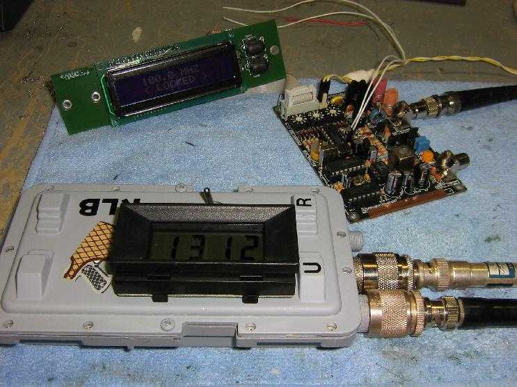
Test setup, 6:1 SWR reading. The Unknown Impedance jack is connected to a pure resistive 300 ohm load.
Test setup, with a "rubber ducky" antenna of unknown value connected. Note how the meter reading is worse than the worst-case reading. This is because the return loss bridge is only meant to determine a resistive impedance mismatch. In real life, antennas will have resistive, capacitive, and inductive impedance mismatches. You'll need one of those fancy MFJ antenna analyzers to measure those values.