Broadcast-Quality FM Transmitter Designs
Index
"Any material
element or resource which, in order to become of use or value to men, requires the
application of human knowledge and effort, should be private property - by the right of
those who apply the knowledge and effort." --Ayn Rand
The following schematic diagrams are being offered in the public domain for the benefit
of those who wish to do their part in the defense of freedom, justice and the American way
by excercising freedom of the airwaves. We will show you plans for building true
broadcast-quality equipment, not that consumer-grade junk that everbody's selling for
$50-$200.
Why am I offering perfectly good
designs for FREE like this? Because I was developing products for the broadcast industry
in the early 1980s, merrily believing it was possible for an inventor like myself to get
products to market with solely my ability to design and build the products and very little
money. Well, nothing could be further from reality. While I could secure the manufacture
process and perfect the designs, I hit a brick wall when I found out how regulated this
industry is. Each piece of apparatus must undergo testing by FCC-approved testing labs, in
order to qualify for FCC type acceptance. I merrily went along and started the process...
and then I found out that I had to pay $20,000 for EACH test, regardless of pass or fail!
Well, that set me back, and I spent the next four years seeking investment capital.
Nothing materialized, and I was out of cash and so I moved on to a new field, sparked by
the computer revolution. And so, as a kind of "poetic justice," I now offer
these designs to the micropower broadcasting community. Use them in good faith.
I must apologize for the messy hand-drawn schematics (and this is slowly changing for
the better), but I work mostly from memory and have little time for documenting stuff as I
change it so rapidly during design. I did, however, manage to get some of this scribbled
down in my notebook over the years and I have scanned those notes into the computer. In my
anxiousness to disseminate this information, I regret that I haven't the chance to have
this all re-drawn in CAD. Please bear with me as you enjoy the privilage of
rapidly-available and much coveted information.
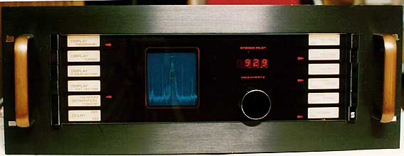 |
| Spectral output of my transmitter.
Spike at left is 2nd adjacent 50dBu station signal. Note that my 120dBu, 700-watt signal
does not overlap it. |
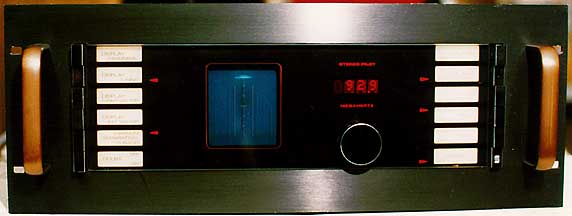 |
| IF bandwidth occupied by my
transmitter. |
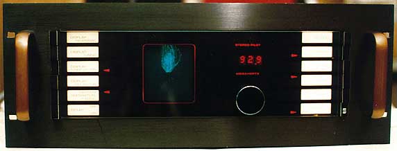 |
| Stereo vectorscope image of my
stereophonic transmission. |
| NOTE: If you have linked directly to this page, we recommend
changing the link to our index_main.htm page. If you have not read our HOW TO page, you should do so first, BEFORE undertaking construction
of any of these circuits. |
FCC WARNING - This equipment, in some instances, is
capable of exceeding Part 15 of the Rules for low-power broadcasting. Please be aware that
it is possible to use this equipment in a manner that can place you in violation of
federal laws. Before you construct any of these projects, you should familiarize yourself
with FCC rules with regard to radio transmission devices, and be aware of the boundry
between legal operation and illegal, unauthorized operation. It is up to you to assume
legal responsibility for your actions as you use this equipment.
This section is now indexed into convenient subsections. Use the chart below to locate
your topic of interest: