For the second article in this series, we'll be focusing on turning a common 2.45 GHz microwave oven magnetron into an Electromagnetic Pulse (EMP) device. Using higher microwave frequencies (shorter wavelengths) is ideal for EMP warfare because they are not as easily attenuated in the target device. A horizontally-polarized, high-power 2.45 GHz pulse is almost perfect for coupling into the PC board traces in most electronic devices. Potential uses out in the "real world" could involve disabling electronic voting machines to prevent illegal alien (Democrat) voter fraud. Another possibility could revolve around disabling an embassy's security system so you can more easily break into them. With a little more tweaking, a device such as this could remotely disable Improvised Explosive Devices (IED) by "zapping" any electronic timers or even pre-detonating their blasting caps. Is there some nutty open-borders politician driving an unshielded electric vehicle you want to take out? Zap!
The basic idea behind this device is to charge a high-voltage capacitor up to around 4,000 volts, and then using a spark gap, "pulse" discharge it into the magnetron. A spark plug will make a perfect spark gap for this particular application. The fast-rising pulse on the magnetron's cathode should even cause it to output a little more power than normal, over 1,000 watts of peak RF power is possible. That's the idea at least... It should be noted that magnetron's operate with a negative voltage on their cathode and "ground" potential on their anode, which is tied to the external case and cooling fins. The magnetron's filament/heater and cathode are also tied directly together. A magnetron is basically modelled as a large zener diode.
This project is very experimental and still needs some tweaking. It will output RF power, but I think the pulse capacitor needs to have a much larger energy storage capacity. The 1 µF capacitor used for testing can only output around 10 joules. This corresponds (roughly) to a magnetron pulse output time of around 10 milliseconds. Since microwave oven magnetrons are not designed to be pulsed this rapidly, I don't think the overall RF output peak power is very high. Extending the time of this pulse, probably with a larger high-voltage capacitor bank, might help to fix this. You'll need to experiment and find out. It should also be noted that microwave oven capacitors, which usually have a "2,000 VAC" maximum voltage rating on them, can be used at significatly higher DC voltages. They appear to easily handle at least 5 kV for short periods of time.

Google Streetview camera cars? Or potential EMP targets?
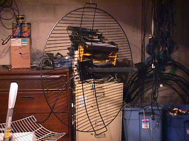
Parabolic antenna reflector used for this project. It's a Lance Industries Model 2536. This 36-inch diameter dish was originally designed for the 2.5-2.7 GHz MMDS band. The gain is approximately 26 dBi and the 3 dB beamwidth is 10 degrees. The focal length is 18-inches.

The only modification to the stock parabolic reflector is to the feed's mounting brackets. Since we'll be making a new feed arm, the original brackets should be drilled out (they are rivoted) and replaced with 1/4-inch stainless steel hardware. This helps to distribute the added weight of the magnetron mounted to the feed arm.

New feed arm made from 1-inch square aluminum tubing. The second little strut should have been 2-inches long, instead of only 1-inch, to help center the magnetron's horn antenna at the focal point. The aluminum feed arm was also an experiment using those "weld with aluminum" sticks you can buy at the hardware store. They say you can use only propane, but in reality, you'll need to use MAPP & oxygen to get a good "weld."
The magnetron and feed horn mount on the left-hand side. The feed arm was designed so that the parabolic's focal point is 1-inch inside the magnetron's feed horn assembly.
The extra arm length on the right-hand side is for mounting the completed parabolic antenna assembly to a mast. Normally the mast hardware attached to the parabolic reflector itself, but since the magnetron and supporting hardware are so heavy, the feed arm was made to carry the bulk of the weight.

Closeup view. Little aluminum L-brackets were added to help increase the feed arm's strength incase those sloppy welds won't hold. This thing is a total hack, so you may wish to design something a little nicer looking.

Inside the filament/cathode filter box on a Panasonic 2M258 magnetron. The large white plastic insulator is a feed-through capacitor and the two inductors keep the 2.45 GHz signal from flowing back into the filament/cathode leads. These should probably be bypassed for this application.

An automotive spark plug will be used for the spark gap. A Champion D14 is shown here. Be sure it doesn't have an internal resistor. A copper pipe ground clamp will be used to hold the spark plug, which will then be attached to the side of the magnetron's case.
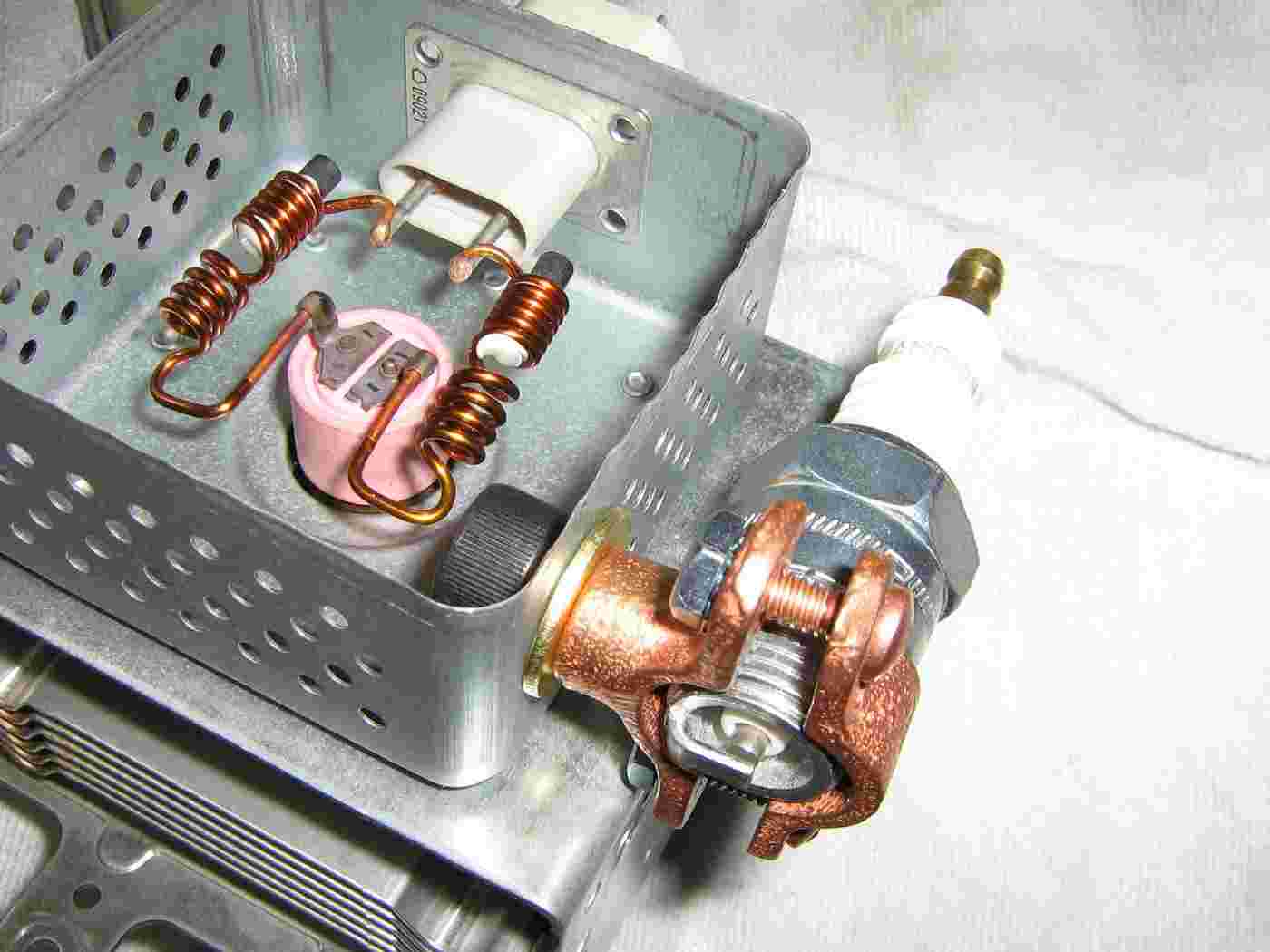
The spark plug is mounted to the magnetron by drilling a hole in the filter box and bolting it to the side. The mounting bolt is 3/8-inch, with brass washers to isolate the copper clamp. Kep nuts were also added to the ground clamp's screws to help secure the spark plug. The spark plug's gap is set to around 0.04-inches, or to fire at around 4,500 volts.

Test setup view showing the feed horn assembly for the magnetron. Refer to the GBPPR HERF Device project in issue #29 for more information on how to salvage the feed horn from an old microwave oven.
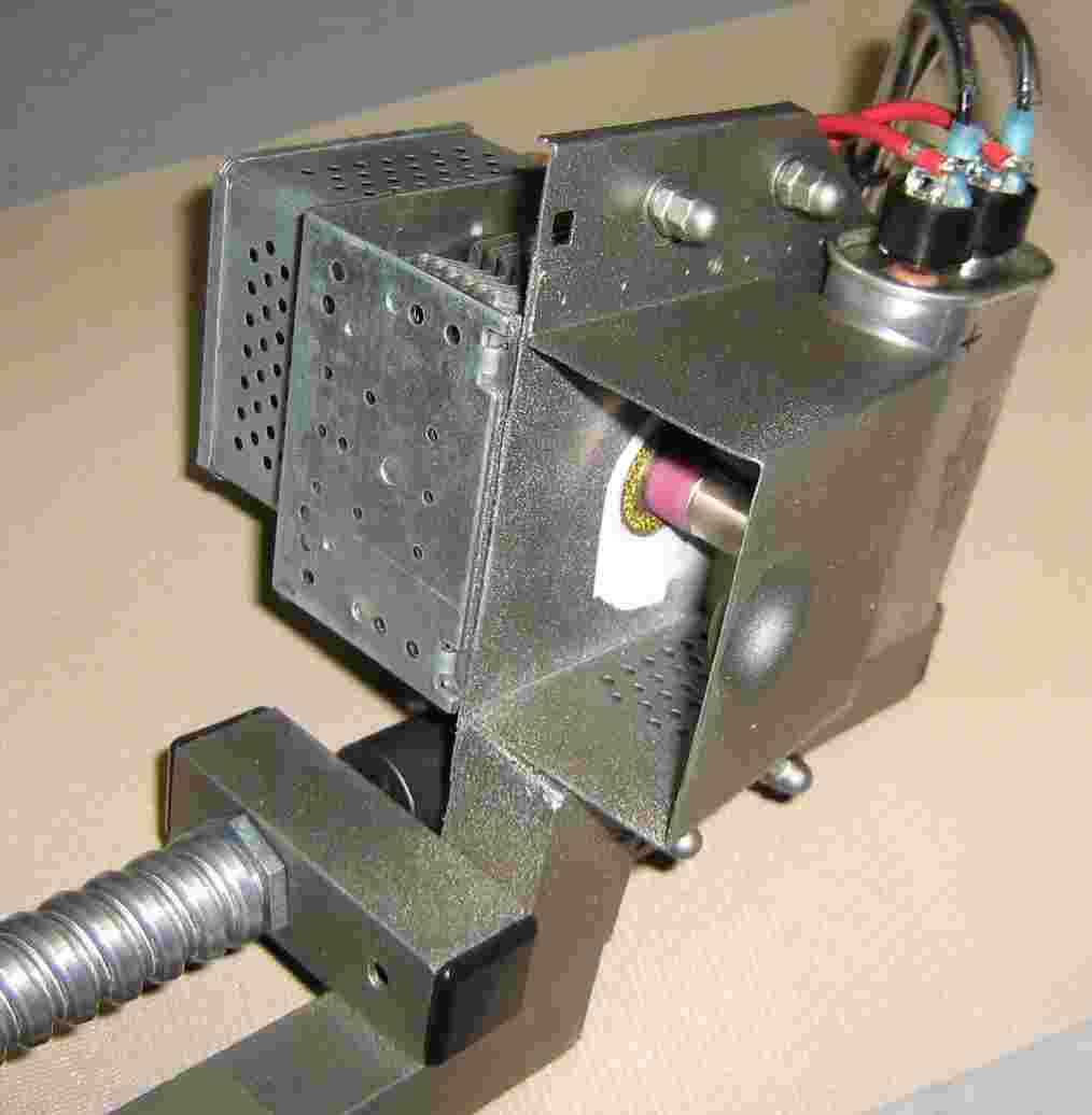
Completed feed view. The high-voltage capacitor charging line comes in via an armored cable. The high-voltage capacitor is epoxied behind the feed horn. This is only temporary, as the 1 µF capacitor proved to be too small in value to really accomplish anything.
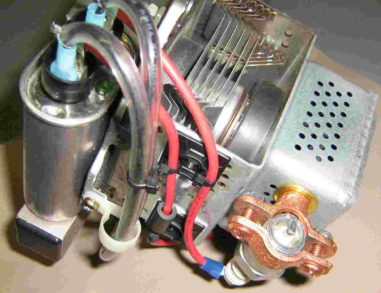
Completed top view. Note the vinyl tubing around the high-voltage charging lines. This worked out quite well. A ferrite bead was slipped around the cathode lead for good luck. Be sure all the high-voltage lines are isolated from the magnetron's case (anode). The spark plug has a handy #8 binding post if you remove the screw cap.
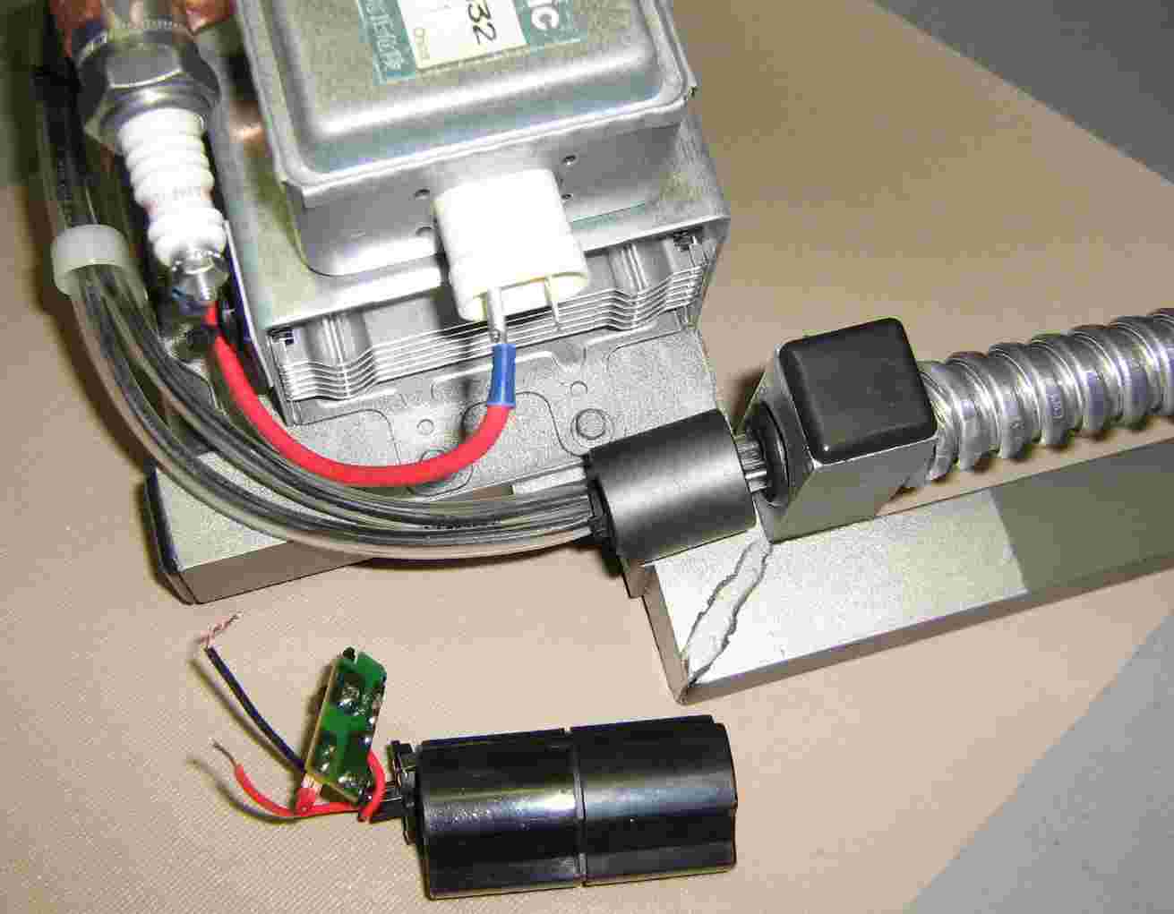
Filament feed view. A 3.6 VDC nickel-cadmium battery pack from a cheap cordless drill is used for the filament supply voltage. This sorta worked out. The filament current is very high, drawing at least 10 amps continuously. The (cheap) nicad batterys would only last for about 30 seconds before needing a recharge. Additional experiments used a separate microwave oven transformer to supply 3.3 VAC filament power. Microwave oven magnetron's have a direct-heating cathode, so the filament voltage can be either DC or AC. The filament supply will need to have high-voltage isolation which means solid-state power supplies are out.
Connect the battery pack via short, heavy-gauge wires and alligator clips. It takes at least two seconds for the filament to properly heat up. Increasing the filament voltage might help to increase the output RF power.
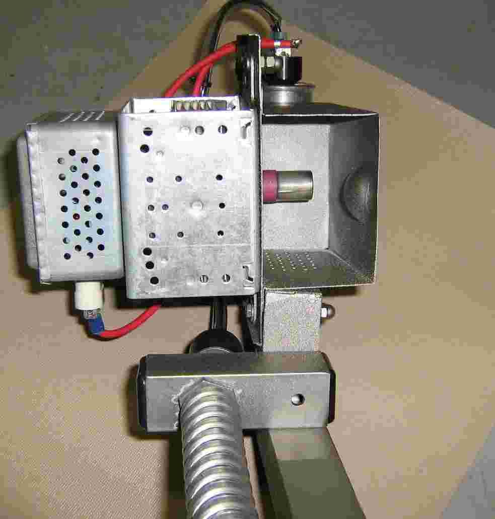
Completed view, looking down the feed horn. The microwaves are emitted from the pink ceramic probe, with the "cap" acting as a capacitor tuning hat.

Completed overall view. This thing does work - sorta. It messed up the screen on an Atari Lynx placed about 2 feet away! Not exactly ground breaking, but there is definitely room for improvements.
Experimenters may wish to try:
- Bypassing the input filament/cathode capacitor and inductor filter network.
- Increasing the filament voltage up to 6 volts.
- Adding extra magnets around the magnetron to increase flux density.
- Increasing the cathode voltage to -5,000 or more.
Does this magnetron experiment stuff kinda sound like how a radar works? Stay tuned!!!!


