Overview
For the third article in this series, we'll be focusing on Electromagnetic Pulse (EMP) devices which have the capability to disable a moving or stationary vehicle. The idea revolves around first charging a high-voltage pulse capacitor up to a fairly high voltage. Then, when a vehicle passes over it - completing the circuit - the capacitor discharges via two spark gaps and two long, metal contact probes. The metal probes help to directly couple the high-voltage, high-current pulse onto the frame or engine block of the vehicle. Since electronic fuel, ignition, and other engine controls are all connected to the vehicle's frame (ground), raising the frame to a high-voltage potential will hopefully destroy any solid-state electronic devices connected to it. The use of two spark gaps helps to maintain the high-voltage on the vehicle's frame for just a few more microseconds. The only problem using this device is that you'll need very high voltages for it to work properly. At least 30,000 VDC should be used to help the discharge "arc" cut through any rust, dirt, or grim on the vehicle's frame. If you use over 100,000 VDC, you might even be able to get the return arc to use a path to Earth ground, and that will almost guarantee a disabled vehicle. Also, the capacitor's value doesn't have to be very large, but you'll want it to have at least 50 joules of energy. The device shown here was only operated at 4,000 VDC - and I couldn't get anyone to let me test it on their vehicle! So, as it is, this method is still very experimental, but it should work. It'll also zap regular electronic devices as well. Just rub the contact probes against it...
How does this vary from the static spark you get when you slide across the driver's seat? Simple, while static sparks are very high in voltage, their source current is extremely low. All automobiles include protection circuits to help "trap" these static spark discharges. The EMP method shown here develops very high currents, which are harder to contain, and this will help to "burn out" any circuit protection components.
Construction Notes & Pictures
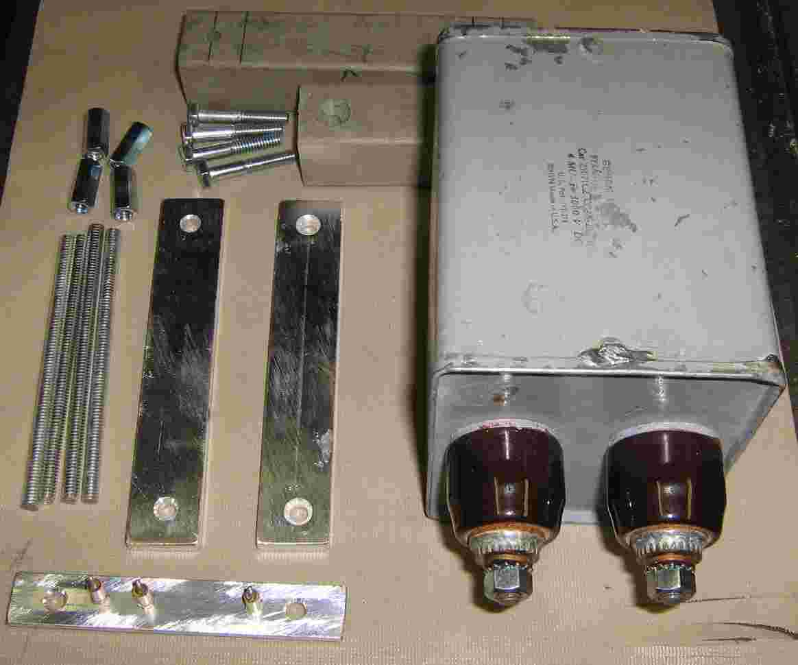
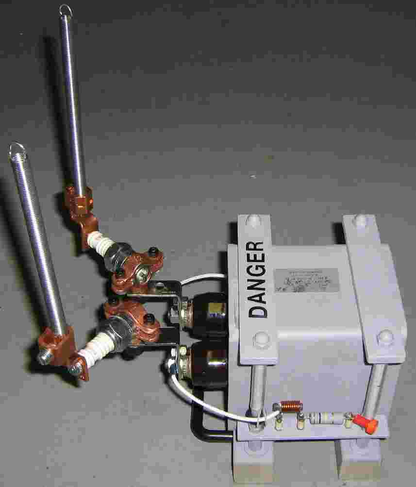
Capacitor mounting hardware overview. The high-voltage GE Pyranol capacitor is on the right.
The capacitor mounting hardware is literally a bunch of junk I found. Plastic fence parts will act as the base, and the capacitor will be sandwiched between two pieces of aluminum bar stock and 1/4-inch allthread and coupling nuts. Small aluminum bars will be mounted on the sides of the capacitor to hold standoff mounting terminals for the capacitor's passive charging components.
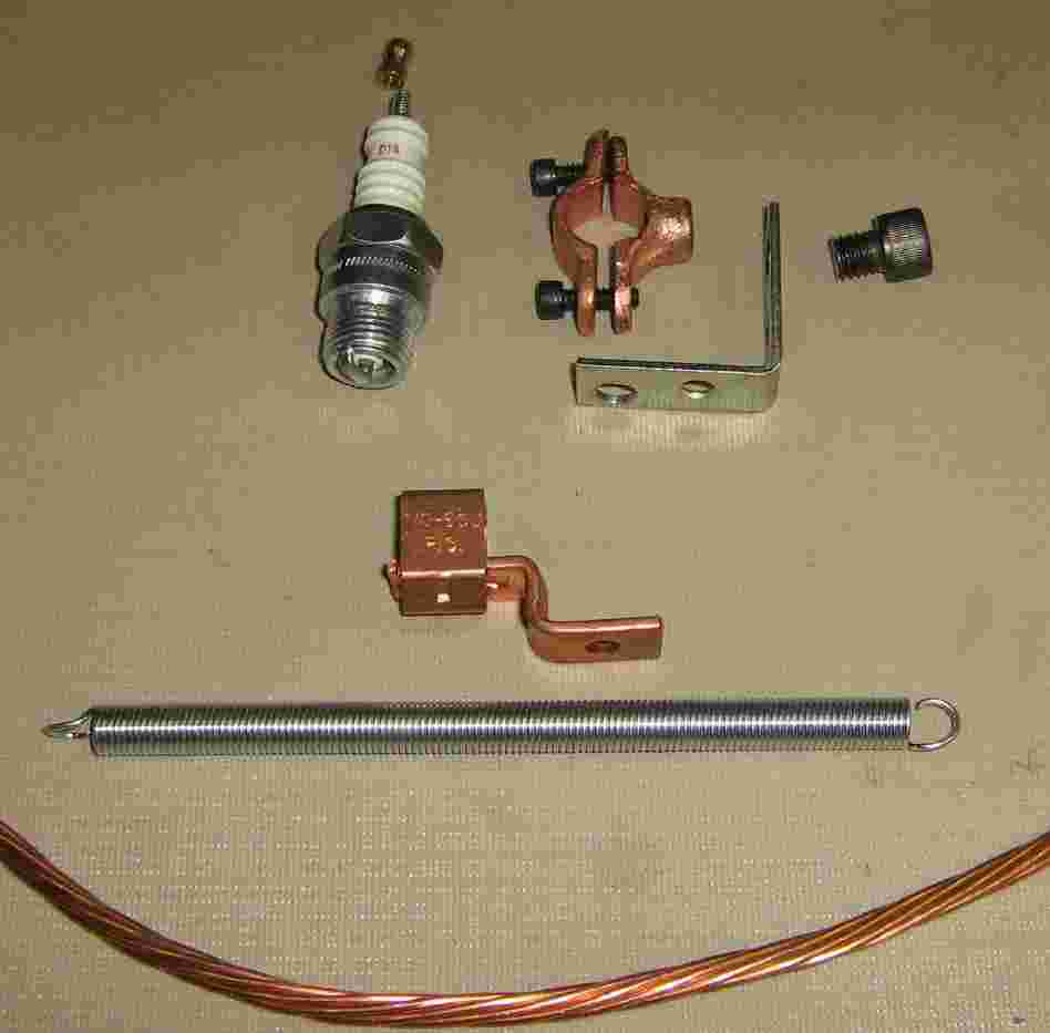
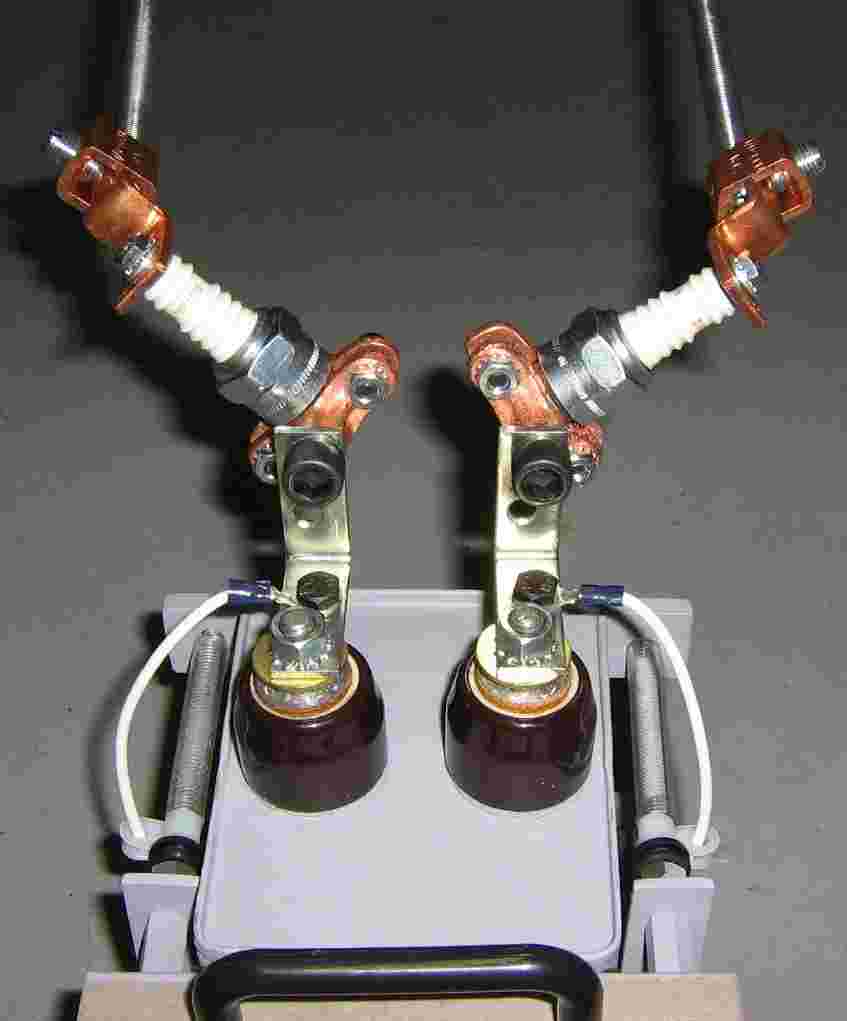
Spark gap parts. A Champion D14 spark plug is secured using a 1/2-inch copper plated split-ring hanger. This is then attached to a 1-inch by 1-inch L-bracket to the capacitor's terminals. Attached to the screw terminal on the spark plug is a 0-6 AWG copper mechanical lug. This is used to hold a 6-inch long, 3/8-inch diameter utility spring (C-239 on the package). The spring acts as the metal contact probe for when an automobile passes over it. If you can't find a spring, or if they are too short, you can use a piece of #6 or #4 copper ground wire.
Constructed high-voltage capacitor mounting hardware. The black strips are pieces of art foam to help protect the capacitor. The 1/4-inch bolts are counter-sunk into the plastic block.
Capacitor charge components. The charge voltage comes in from the right via a banana jack. It then passes through a five watt, 100 kohm isolation resistor. This isn't a real high-voltage resistor, but it'll work in a pinch. Next, is a 1.8 µH inductor which was salvaged from an old microwave oven magnetron's filament line. This helps to further isolate the discharge pulse from the charging circuits. The value is probably too low, but oh well. Also note how the components are mounted on isolated standoffs to prevent high-voltage arcing to the metal frame.
There is vinyl tubing over the threaded connecting rods for added protection. A rubber grommet and a plastic cable clamp help to route the charging line away from the metal frame and mounting hardware.
Alternate view with the spark plug hardware mounted to the capacitor. Large brass washers help to secure the L-brackets to the capacitor's terminals. A handle was also added to the plastic capacitor mount so it's easier to carry. You'll want to avoid touching the terminals when handling this device.
Underneath view of the the spark plugs and their associated mounting hardware. The WHITE wires are for the capacitor's charging lines. High-voltage oil capacitors like this one are not polarized.
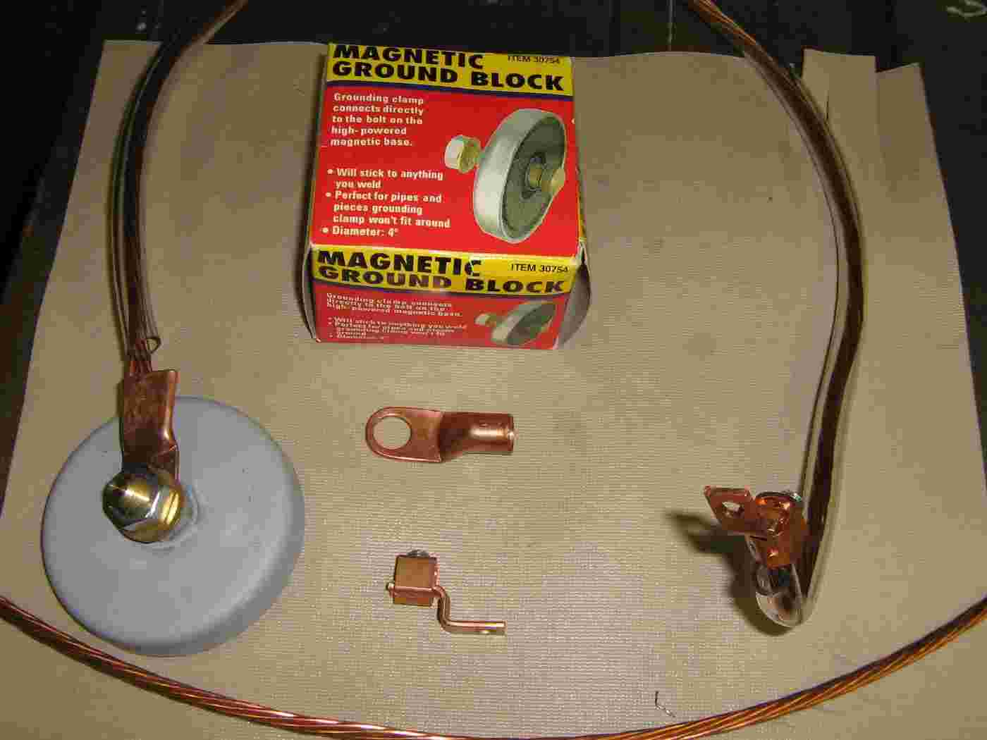
For a sure-fire method of disabling a stationary vehicle, you'll want to make up something like this. Take two Harbor Freight Tools Magnetic Ground Blocks (Item #30754) and attach two long lengths (about three or four feet should do) of #4 or #6 copper ground wire. Then add a copper mechanical lug to one end, and a copper ring terminal to the other end of the wire. Securely attach the ring terminal end to the magnetic ground block. You'll also want to run the copper wire through a piece of vinyl tubing for added high-voltage protection.
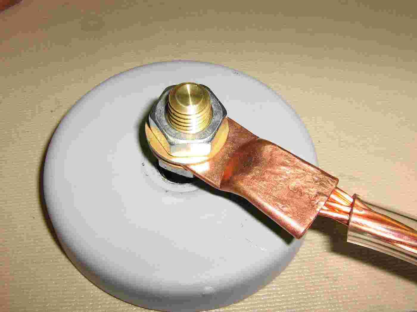
Closeup of the copper ring terminal attached to the magnetic ground block. The copper ring terminal was attached to the ground wire using a vise because I didn't have one for use on smaller diameter wire.
A handy addition is a foam handle. You'll want to add this if you are positioning the magnetic ground contact blocks while the capacitor is already charged. The pieces of foam tubing comes from those cheap carabiners you can buy at the hardware store.
View of the two magnetic ground blocks and their attached wires. You'll want to place one of the ground blocks on the engine or oil pan and the other on the vehicle's frame. This should help the discharge pulse to flow from the engine to the frame, blowing out any electronic engine controls in the path. Of course, you'll probably want to experiment ahead of time.
View showing how the copper wires are attached to the spark plug screw terminals. This particular setup is very fragile! An updated version should include better mechanical support.
Stationary vehicle disabling device - overall view.
Schematic / Block Diagram
Notes
- Higher resolution pictures and the original project article are available in GBPPR 'Zine Issue #40
- Remote Vehicle Disabling System U.S. Patent 5,293,527 (578k PDF)
- Vehicle Disabling Device and Method U.S. Patent 5,503,059 (784k PDF)
- Compact, Portable, Vehicle Disabling Device and Method U.S. Patent 5,645,137 (325k PDF)
- In-Road Microwave Vehicle Stopper U.S. Patent 5,907,290 (34k PDF)
- Electromagnetic Vehicle Disabler System and Method U.S. Patent 6,371,000 (125k PDF)
- Automobile Engine Disabling Device U.S. Patent 6,723,225 (55k PDF)
- Engine Disabling Weapon U.S. Patent 5,952,600 (94k PDF)
- System and Method for Selectively Disabling a Vehicle U.S. Patent 7,412,321 (174k PDF)
- Non-Lethal Technologies Road Patriot
- HSV Technologies
- History Channel on Location Xtreme Alternative Defense Systems "StunStrike Car Xapper" in action. (YouTube)
- XADS StunStrike Car Xapper Demonstration That's Impossible segment. (37M WebM)
- XADS StunStrike Car Xapper Demonstration for The History Channel Behind the scenes footage. (YouTube)
- Microwave Beam Stops Cars Dead
- Electromagnetic Pulse Cannon Could Demo Car-Stopping Power Next Month
- Cig-Lighter EMP Blaster Down to Suitcase Size, Apparently
- This EMP Cannon Stops Cars Almost Instantly
- Eureka's EMP Cannon Destined for the Marines?
- Electromagnetic Pulse Gun to Help in Police Chases Note: Slashdot posters are the dumbest people on the planet.
- Real World EMP Effects on Motor Vehicles by Michael Z. Williamson
- Eureka Aerospace High-Power Electromagnetic System EMP vehicle disabling system. (Videos)
- High-Power Compact Microwave Source for Vehicle Immobilization, Final Report by Eureka Aerospace (1.7M PDF)
- RF Safe-Stop Shuts Down Car Engines with Radio Pulse (Slashdot Entry) (Brochure)
- Radio Beam Device Can Disable Car and Boat Engines from 50m
- Diehl Defense Convoy Protection High-Power Electro Magnetics (HPEM) effectors offer the possibility of directing impulses against different electronic systems with the objective of causing malfunction. (HPEMcarStop) (HPEMcase)
Other Related GBPPR Projects:
- GBPPR Electromagnetic Pulse Experiments - Part 1
- GBPPR Electromagnetic Pulse Experiments - Part 2
- GBPPR Microwave Oven & EMP Experiments
- GBPPR HERF Device


