It is possible to detect some GPS receivers by the electromagnetic radiation they emit. GPS L1 receivers all generate a pseudo-random digital "noise" source at a chiprate of 1.023 MHz. These pseudo-random digital signals are then used to correlate against the data received from a GPS satellite's transmitted Coarse Acquisition (CA) data stream at 1575.42 MHz. By searching for any unintentional radiation of the receiver's 1.023 MHz digital noise signal (or its harmonics) you can pin-point the general location of an operating GPS receiver. By verifing that you "hear" a data stream at 1.023 MHz, 2.046 MHz, 3.069 MHz, etc. you can be sure that you've found a GPS receiver.
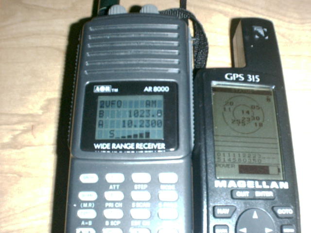
All you need to do this is a cheap AM radio receiver. One with the fancy PLL tuning will be useful, though. Tune the AM radio to approximately 1.023 MHz and pass it over an operating GPS receiver. You should hear a distinct, high-pitched digital "whine." That is, if you are not receiving any nearby AM radio broadcasts, which can be a problem. This receiving method will work best indoors or inside a shielded metal or concrete enclosure, which reduces the chance of external RF interference.
If you wish to get fancy, you can replace the Intermediate Frequency (IF) filter on the AM radio with one which has a much narrower bandwidth. This will help to eliminate any interference and reduce false signals. The ARRL Handbook for Radio Amateurs will cover the designing and building of suitable crystal IF filters. You could also try using a high-end shortwave receiver fed with a tuned ferrite stick or loop antenna.
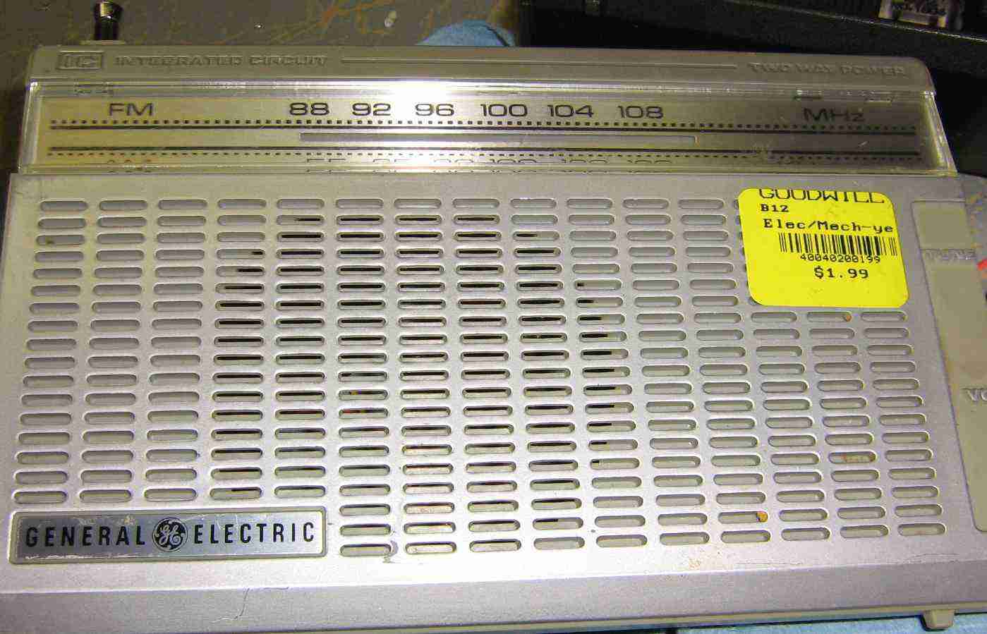
AM radio used for this project.
It is a General Electric Model No. 7-2650A, FCC ID: AEX9YD7-2650. Get ahold of a bunch of different AM radios and try to choose one whose internal PC board will fit snuggly inside a piece of PVC pipe. Be sure the ferrite rod antenna is in a horizontal position (with respect to your body) when holding it.
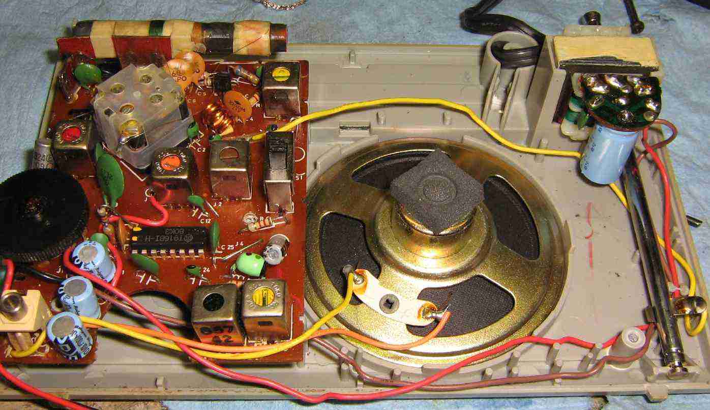
Internal view of the AM radio. It can be powered from either a 9 volt battery or 120 VAC. Be sure to note any speaker, volume, tuning, or antenna wiring when you take it apart.
Picture of the AM radio's main PC board. You'll need to note the incoming +9 VDC line (the red & black wires) and the speaker wires (orange & yellow). The volume control potentiometer will also need to be unsoldered (or replaced, in this case) and mounted to the GPS Receiver Detector's handle assembly.
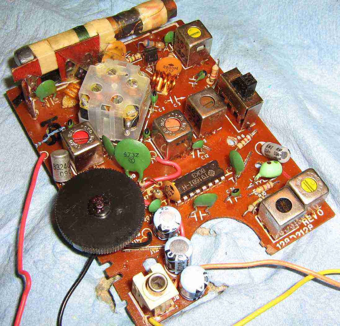
The ferrite antenna's main pick-up lobe will be horizontal to its axis. There will be sharp nulls on both ends. This can be useful for "nulling" any external RF interference.
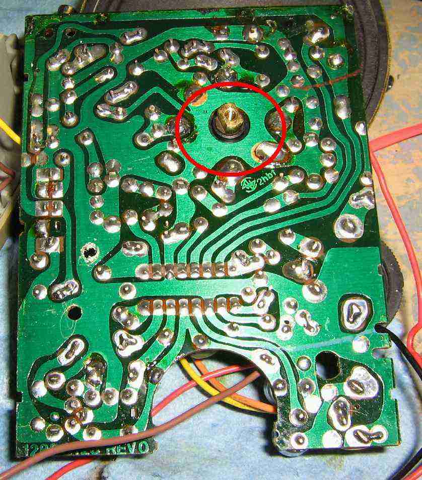
Solder side view of the AM radio's main PC board. Be sure to tune the AM radio to approximately 1.023 MHz before construction. Remove the plastic tuning wheel and add a dab of hot-melt glue to the capacitor's tuning post (red circle) to prevent the received frequency from drifting.
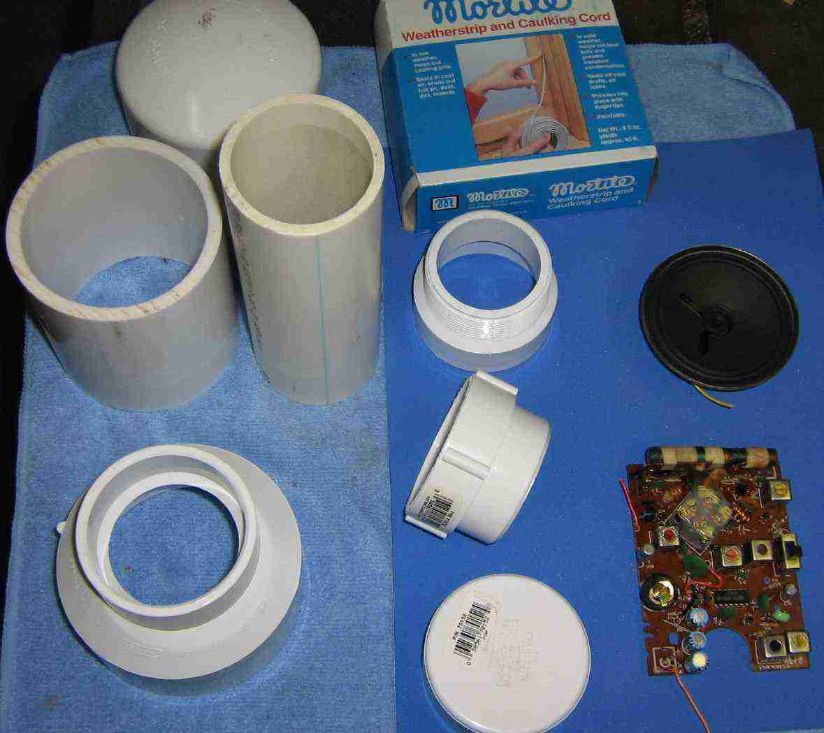
Some of the PVC parts used to make the GPS Receiver Detector. From the top left-side, a 3-inch diameter PVC cap, a 4-inch long piece of 3-inch diameter PVC pipe, next to that is a 6-inch long piece of 2-inch diameter PVC pipe, which will be the handle. Below that is a 3-inch to 2-inch PVC reducer/coupler. On the right-side, from the top, is some weatherstrip caulking cord, a 2-inch diameter PVC threaded male adapter and a "clean-out" thingy. Below that is a 2-inch PVC cap. Finally, the AM radio receiver board and speaker.
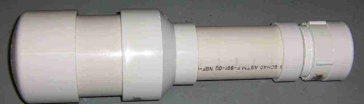
Put it all together so it looks something like this. The AM radio will be mounted in the left-hand section, with the ferrite antenna just behind the PVC cap.
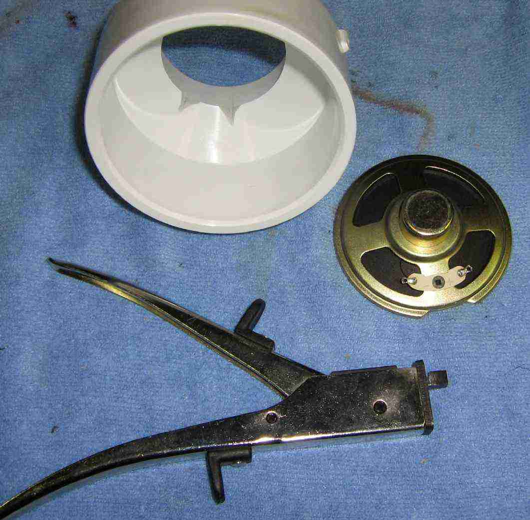
The AM radio's speaker should be mounted inside the 3-inch to 2-inch PVC reducer. You'll need to file the reducer so there is space for the control wires to pass through. You may also need to trim some metal from around the speaker. A "nibbler" tool will do this easily and without damaging the speaker's cone.
Mount the speaker inside the 3-inch to 2-inch PVC reducer like so, using the weatherstrip caulking cord to hold it in place.
Fit the 3-inch and 2-inch diameter pieces of PVC like so. Line the 3-inch diameter piece with art foam. This will be used to "hold" the AM radio. It is probably a good idea to spray in the inside of the PVC pipe with some sort of metallic or ferrite EMI spray.
Fit the AM radio's receiver board like so. Make sure the ferrite antenna goes into the space created by the 3-inch PVC cap.

Add a 9 volt battery holder clip inside the PVC handle.
Internal view. It should look something like this. Note the large wire bundle on the left. This will go underneath the speaker and into the PVC handle.
The wire bundle consists of the wires for the volume potentiometer, +9 VDC (via an on/off switch), ground, and an additional speaker output which will be used to drive a signal strength meter.
Rear view of the handle assembly showing the threaded adapter and cap. The new 10 kohm volume potentiometer has an attached on/off switch to control the radio's +9 VDC. The additional speaker tap is brought out to a 1/8-inch mono jack.
Pretty it all up. Note: Also makes a good tool to beat Emmanuel Goldstein over the head with.
Parts for making a visual signal strength meter. Shown are two 1.5-inch diameter PVC caps, an analog strength meter from an old stereo system, and a 1/8-inch mono jack.
You'll need to make or buy a small 1/8-inch to 1/8-inch patch cord to connect to the signal strength meter.
Completed signal strength meter. Mount it behind one of the PVC caps. Secure the meter into position with some epoxy. A small ferrite bead was added to the rectifier board's input.
The signal strength meter reading will be relative.
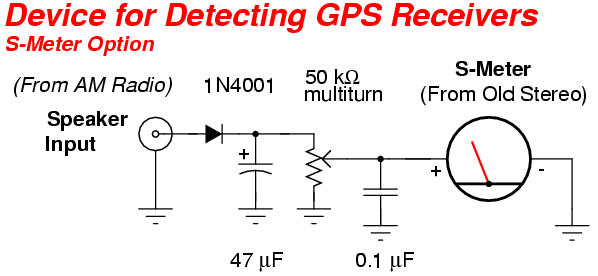
To adjust it, first turn on the GPS Receiver Detector and adjust the volume control until it reads around "2" on the signal strength meter. Bring it near an operating GPS receiver. The speaker should emit a high-pitched "whine." Adjust the 50 kohm potentiometer on the rectifier board so the meter reads full scale. Move the GPS Receiver Detector away from the operating GPS receiver and verify the signal drops back down to around "2". Once the meter is set, you can leave it. You'll have to tune the volume knob back to the same position if you wish to utilize the meter, though.
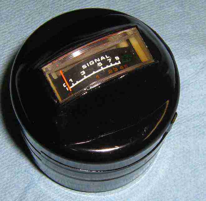

Overviews of the completed signal strength meter. The analog meter is shown on the left, the input to the rectifier board is on the right.