Operation
The main trick when performing targeted depopulation, just like in magic, is being in two places at once.
While I don't know how to to that, I can fake it! And that's all you really need to convince the court system that you are, in fact, "non-guilty."
GPS basically works by transmitting a preciously timed psuedo-random "noise" signal from an orbiting satellite down to your GPS receiver. Inside your receiver, a similar psuedo-random "noise" signal is also generated. The GPS receiver tries to sync the phase of these two signals together. Since the distance to the satellite is known, the amount of phase-shift (time) that this syncing process takes can be calculated into a distance. When taking into account multiple satellites and multiple readings, your global longitude and latitude coordinates can be determined.
The GPS calculations are based around the speed-of-light (electromagnetic radiation) through the atmosphere and ionosphere. If we could somehow alter that speed, we could also alter the final determined coordinates.
Now, how in the hell are we going to alter the speed-of-light, especially with only a hacker's budget? Simple, we'll make a "RF delay line" out of some scrap coaxial cable. Our "delay box" project will receive the weak GPS signal at one end, delay the signal to approximately 60 - 80 percent the speed-of-light over a distance of several hundred feet, then we'll amplify this delayed GPS signal, and finally transmit it to our target GPS receiver. Since this "new" signal has been artificially "delayed" in its journey from the orbiting satellite, the GPS receiver will think that it is actually someplace where it isn't. Your new GPS coordinates will be a few hundred feet off from where you actually are.
This overall concept does appear to work, but it's still very experimental. And no, encrypting the signal will have no effect on the outcome, as this is a "layer one" physical attack. The only way to really prevent this type of "spoofing" is to use a very directional GPS receiver antenna or an antenna system with very sharp nulls towards the horizon and proper polarization. Also, since the transmitted "delayed" signal can have a higher received power level then a signal received directly from the GPS satellite (approx. -130 dBm), GPS receivers should start tracking the received power.
Block Diagrams
Construction Notes & Pictures
Homebrew coaxial delay line.
This is approximately 233-feet of surplus Belden 9269 RG-62A/U coaxial cable. Yes, the 93 ohm impedance is wrong, but it will still work and it can be had for free as businesses get rid of their old ARCnet and IBM 3270 terminal networks.
We'll wind the coax around an AC extenstion cord thingy.
Completed coaxial delay line with BNC connectors added to each end.
Belden 9269 RG-62A/U coaxial cable has a velocity of propagation equal to 84% the speed-of-light and a nominal delay of 1.21 nanoseconds per foot.
This entire delay line assembly will "slow" the received GPS signal by approximately 282 nanoseconds. This corresponds to a final 275-foot "error" on the GPS receiver. This delay line's total attenuation loss will be around 26 dB.
Standard 50 ohm impedance Belden 8216 RG-174 coax has a nominal delay of 1.54 nanoseconds per foot. RG-174's narrow diameter also makes it ideal for constructing physically small delay lines, but it will have much more attenuation loss.
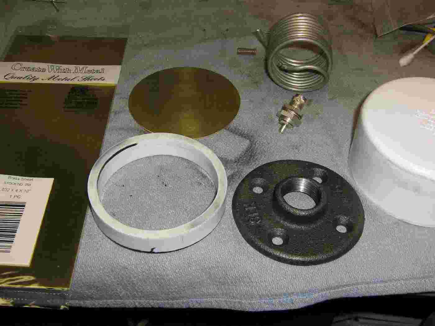
Parts for the GPS receive antenna.
For this experiment, the first thing we'll construct is the GPS receive antenna. This is the antenna which will receive the direct satellite transmissions and will be mounted on a mast away from the delay box. This GPS antenna is a slight modification from the one in the October 2002 QST article "An Inexpensive External GPS Antenna" by Mark Kesauer (N7KKQ).
This article is available online at www.arrl.org/tis/info/pdf/0210036.pdf. Study it very caerfully before constructing this version of the antenna. We'll be replacing the PC board antenna elements in the original article with a piece of UT-141 semi-rigid coax. It will also be mounted inside a 3-inch diameter PVC pipe enclosure.
The parts shown above are, from the left, 0.032-inch thick brass sheet (K&S #253) cut into a 3-inch diameter disk, a piece of 3-inch PVC pipe for use as a template, a 3/4-inch pipe floor stand, a flat 3-inch PVC cap, a panel-mount BNC connector, and some UT-141 coax.
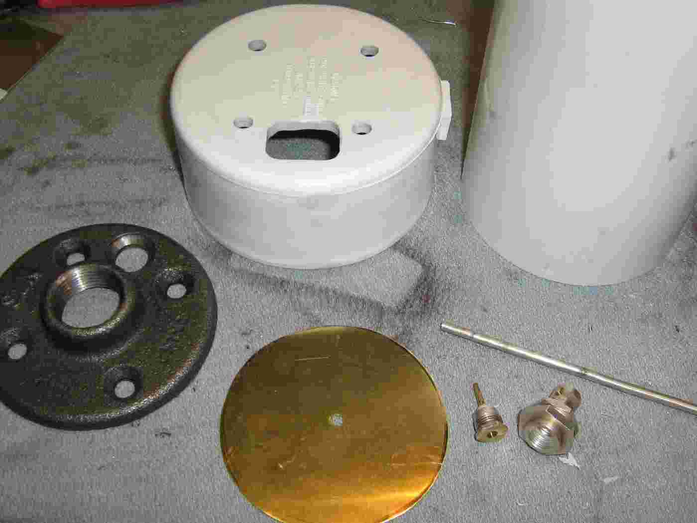
Begin the antenna construction as shown.
On the left, is the pipe floor stand with a large hole drilled in it to fit the panel-mount BNC connector. The PVC cap has been drilled so the pipe floor stand can be attached to the bottom to act as a mast mount. The larger hole allows the panel-mount BNC connector and coax to feed the antenna.
On the upper-right is a length of 3-inch diameter PVC pipe which will be used for the antenna's enclosure.
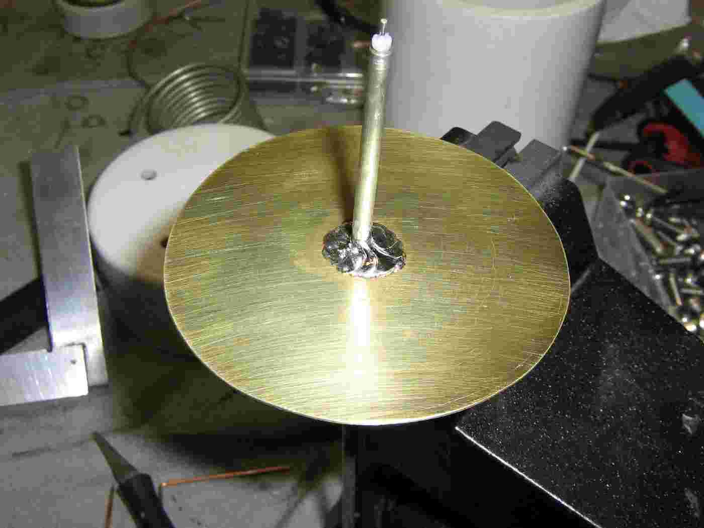
A hole has been drilled in the center of the 3-inch diameter brass sheet to pass the UT-141 coax.
Solder the UT-141 coax to the brass sheet as shown. The distance from the brass ground plane to the shield-end of the UT-141 coax is 1.78-inches.
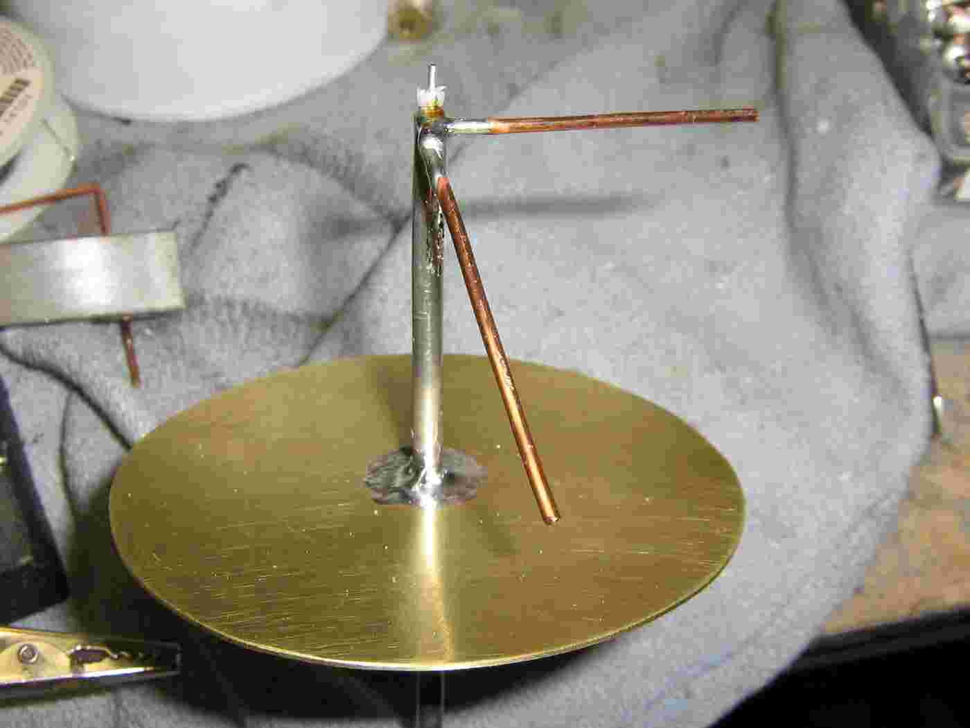
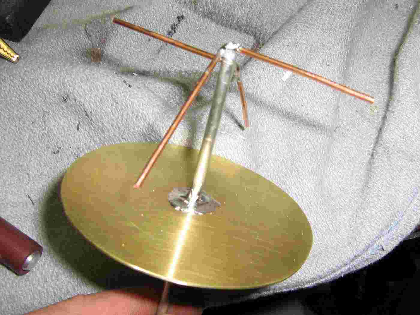
First #14 copper wire antenna element added to the UT-141's shield.
Follow the instructions in the QST article for adding each antenna element. The horizontal element will be 1.51-inches long and the 45° "down" element will be 1.82-inches long. You may have to trim the horizontal elements down slighty to fit inside the 3-inch PVC pipe enclosure.
Second #14 copper wire antenna element added to the UT-141's center conductor.
The picture looks confusing, but the QST article provides much more detail. It will also make more sense while you are actually building it.
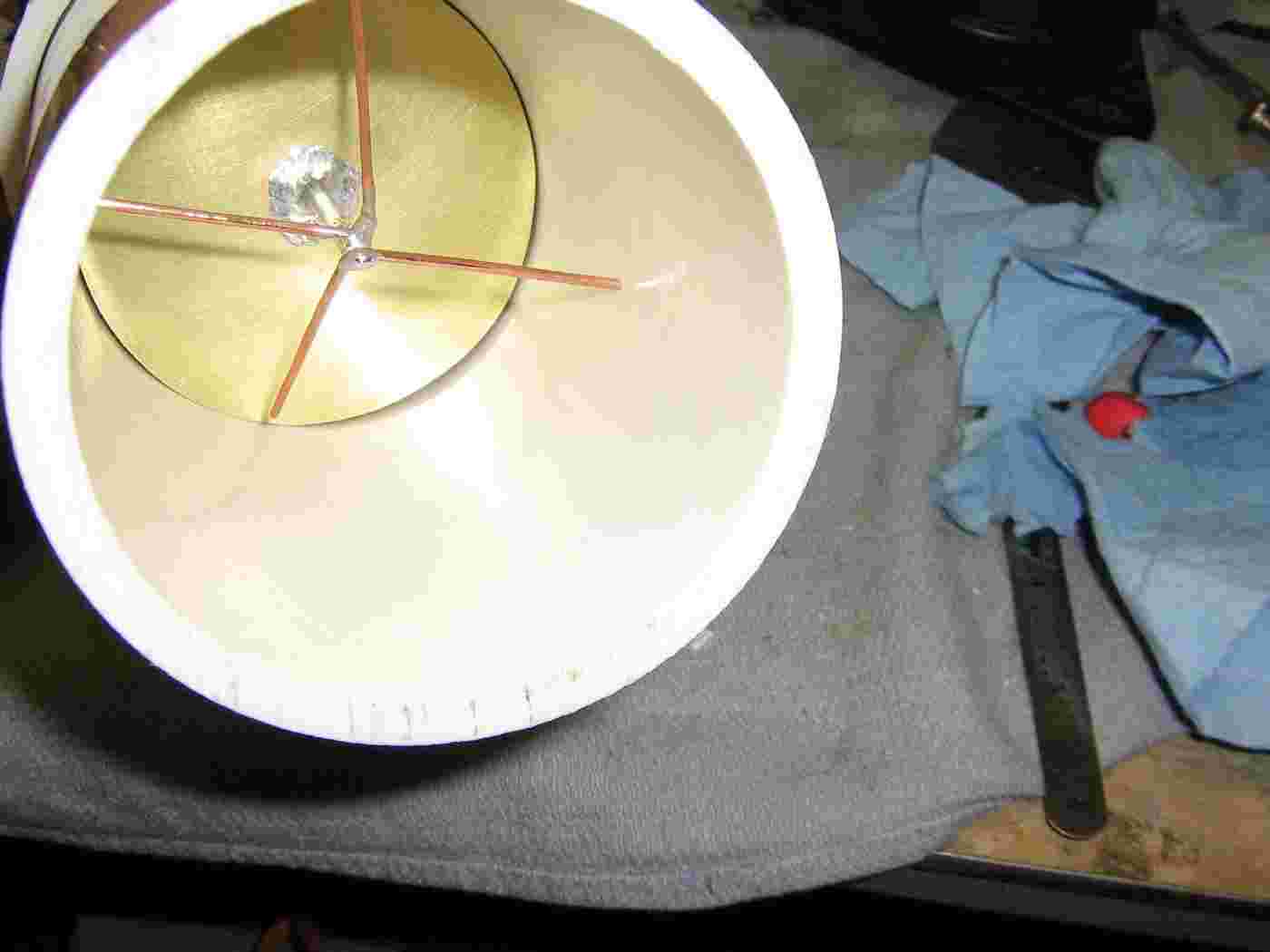
Final GPS receive antenna construction.
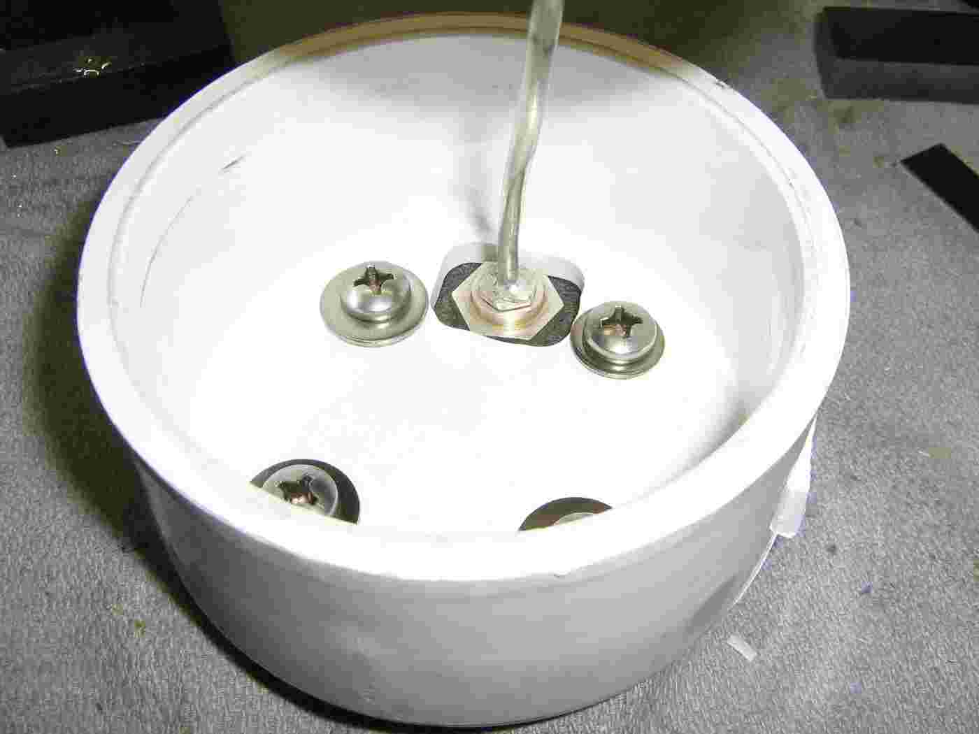
Solder the UT-141 into the panel-mount BNC connector with enough "slack" to allow you to adjust the antenna's final position inside the PVC enclosure.
Use stainless steel hardware to mount the floor pipe stand to the PVC cap as shown. Also mount the panel-mount BNC connector at this time, making sure that the locking nut is very secure.
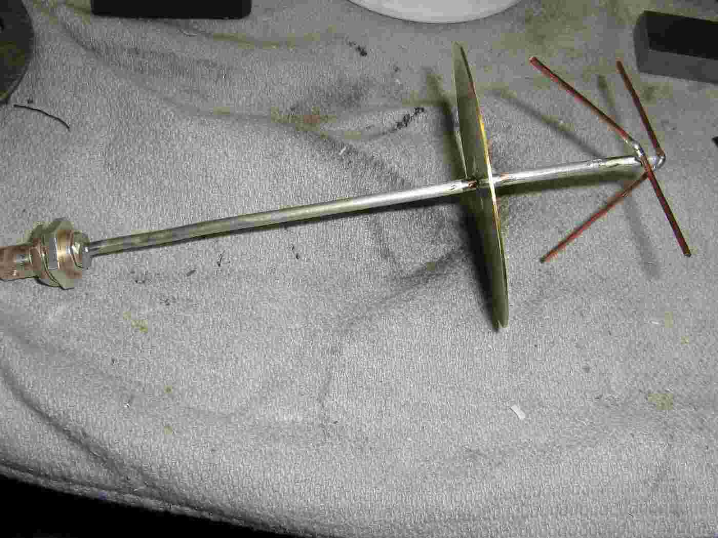
Finished GPS receive antenna without the PVC enclosure.
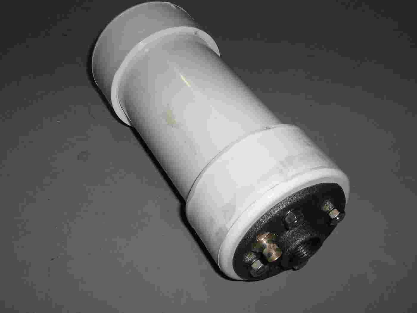
Finished GPS receive antenna inside a 12-inch long piece of 3-inch diameter PVC pipe. You may have to trim the elements down a little bit for it to fit. This shouldn't effect the antenna's overall performance too much.
Add another PVC cap to finish off the project.
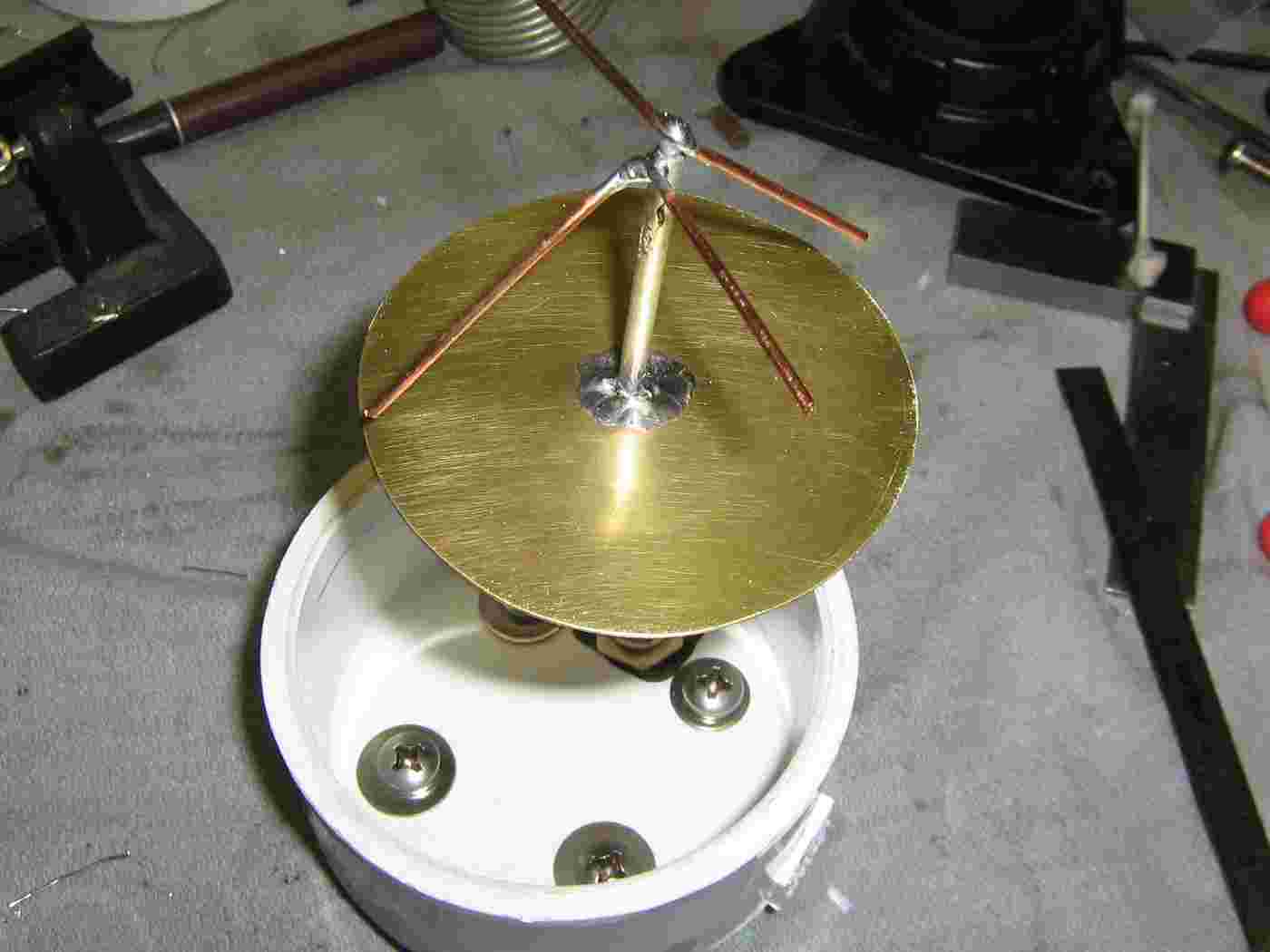
Completed GPS receive antenna overview.
The antenna can now be mounted to the top of a mast made out of standard 3/4" galvanized plumbing pipe.
Initial GPS delay spoofing testing. Completely passive (antenna to delay line to antenna). No active amplifier elements used.
The GPS receive antenna was mounted on a 8-foot high mast placed about 10-feet away from the testing location. The delay line was added inbetween, and the output sent to a Ramsey Electronics LPY2 Yagi antenna placed next to the target GPS receiver.
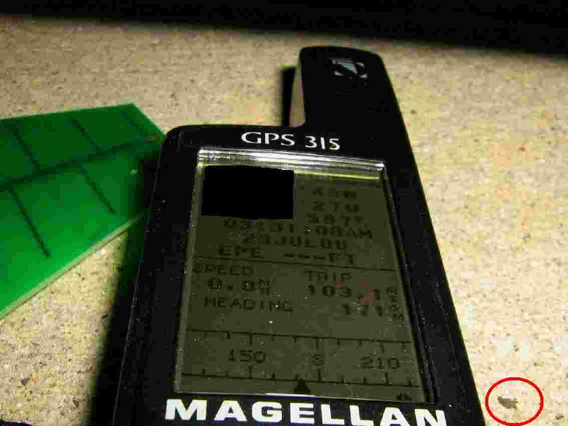
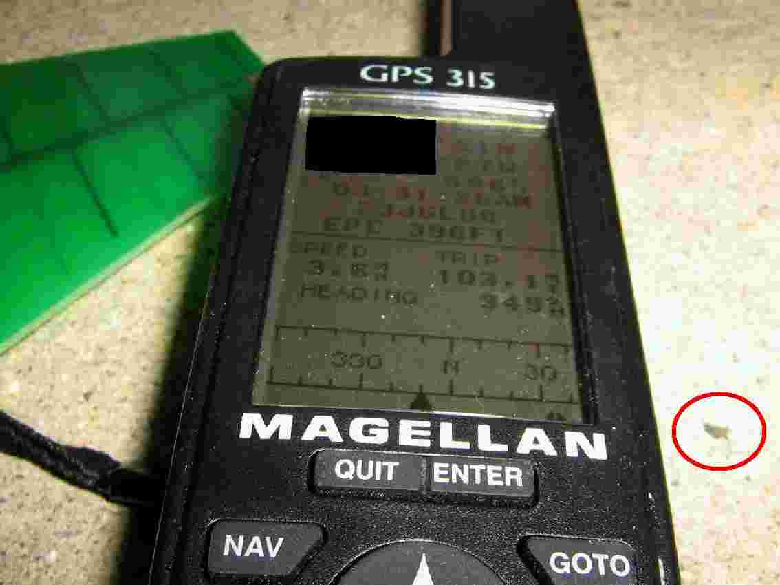
The (censored) starting non-spoofed coordinates are:
 Latitude : XX° XX' 48" North
Longitude : XX° XX' 26" West
The circled spot on the concrete will be used to reference the GPS receiver's position so you know it hasn't been moved.
(The GPS receiver times will be off after I realized the camera angle sucked.)
The delay line is now connected and the GPS receiver was shielded from receiving a direct satellite signal.
After 30 seconds or so, the spoofed coordinates are now:
 Latitude : XX° XX' 49" North
Longitude : XX° XX' 27" West
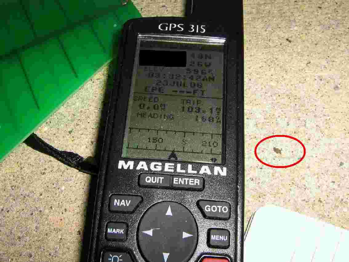
About a minute later, the "spoofed" coordinates now read:
 Latitude : XX° XX' 51" North
Longitude : XX° XX' 27" West
Also note the high Estimated Position Error (EPE), 396-feet. Also, for some reason, the GPS receiver thinks it is traveling 3.6 miles per hour.
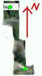
Censored Terraserver overhead picture of the testing location.
The green spot in the lower-right is the "non-spoofed" starting point and the upper-left one is the final "spoofed" coordinates.
The spoofed location is approximately 311-feet northwest from the actual GPS receiver's location. This is fairly close to our estimated "error" of 275-feet.
"So you moved some GPS coordinates a few hundred feet, what's the big deal?"
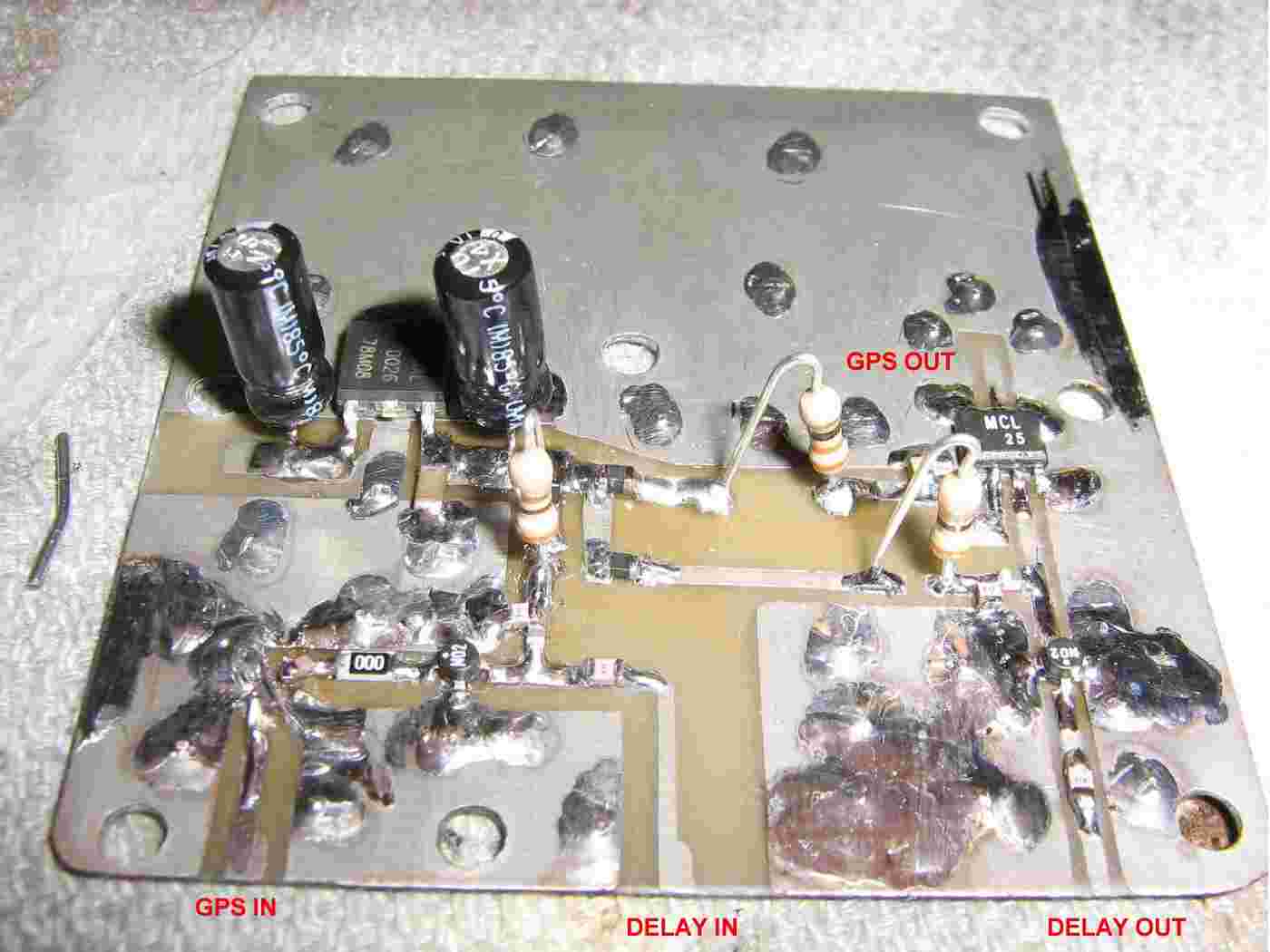
Active amplifier PC board overview.
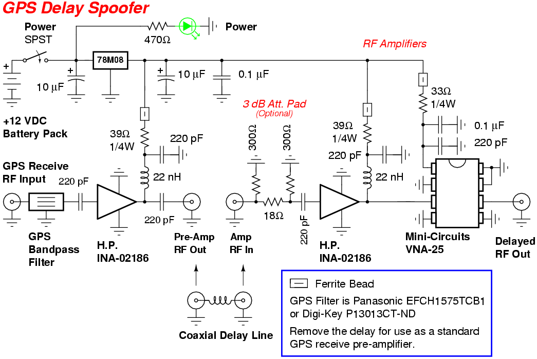
A H.P./Agilent INA-02186 low-noise MMIC receive pre-amplifier is on the lower-left. The INA-02186's RF input is fed through a Panasonic EFCH1575TCB1 GPS bandpass filter, which is an absolute pain to solder, so we'll make it optional.
The INA-02186's RF output is then sent to the coaxial delay line. The other end of the delay line is amplified by another INA-02186 low-noise MMIC and a Mini-Circuit's VNA25. The final output is then sent to the GPS transmit antenna.
For some reason, this circuit doesn't seem to work. The test target GPS receiver could not lock onto a signal. It's probably better to use lower-gain MMIC stages or stick with no active amplifiers and just use directional GPS antennas on each end.
Pin-out of the Panasonic EFCH1575TCB1 GPS bandpass filter.
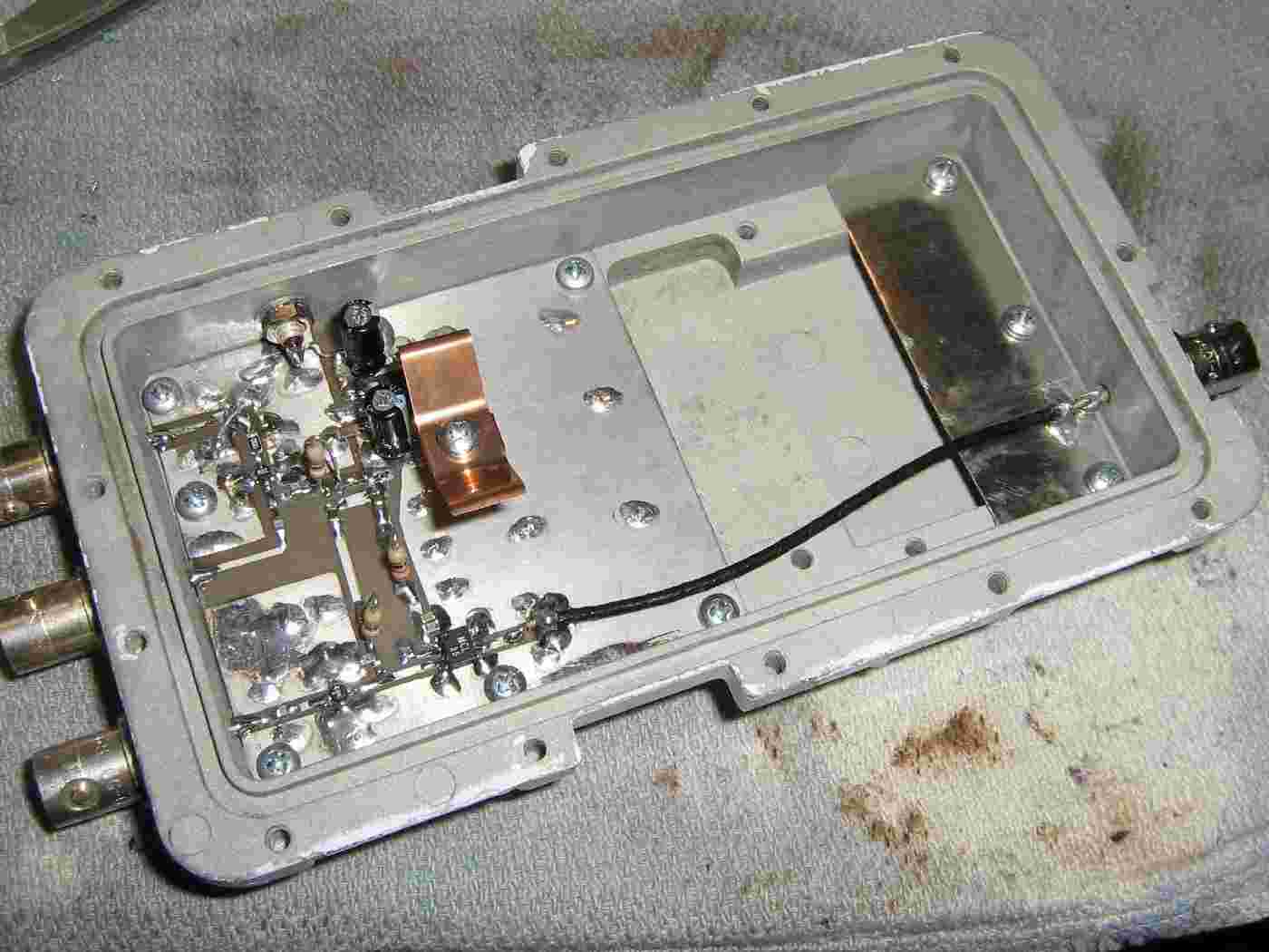
Overview of the amplifier PC board mounted in an old California Amplifier MMDS downconverter case.
A BNC connector is mounted to the rear of the case for the RF output and a piece of tin acts as the ground plane for soldering the coax.
Schematic
Datasheets & Notes
- Higher resolution pictures and the original project article are available in GBPPR 'Zine Issue #53
- The slight artificial "delay" can also be used to disrupt systems which use GPS-based time synchronization. Most notably, CDMA-based cellular phone networks and cellular phone-based "counter-stealth" radar systems.
- Panasonic EFCH1575TCB1 GPS Bandpass Filter (1M PDF)
- H.P./Agilent INA-02186 MMIC Amplifier (75k PDF)
- Mini-Circuits VNA25 MMIC Amplifier (55k PDF)
- Belden 9269 Coax Specifications (29k PDF)
- Countermeasures for GPS Signal Spoofing (153k PDF)
- Think GPS Offers High Security? Think Again! (2.8M PDF)
- Vulnerability Assessment of the Transportation Infrastructure Relying on GPS (478k PDF) (Slides)
- NS/EP Implications of GPS Timing by LeeAnne Brutt (451k PDF) (HTML)
- The Global Positioning System: A Shared National Asset
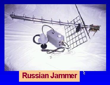
- Picture of a Russian GPS Jammer
- Iowa Farmer Sells GPS-Based Crop Circle Creation Kit
- Secure GPS for Aviation
- GPS Spoofing Countermeasures by Jon S. Warner & Roger G. Johnston
- GPS Vulnerability Assessment Team (VAT)
- U.S. Navy NAVSTAR Global Positioning System Homepage
- Global Positioning System Overview
- philosecurity: GPS Spoofing
- Schneier on Security: GPS Spoofing
- GPS NMEA Spoofing Hack a Day Entry
- Spoofing GPS and Getting Your Own UAV Hack a Day Entry
- Cornell Chronicle: Spoofing GPS Receivers (Cornell University GPS Laboratory)
- How Good is GPS? The civilian-military relationship and the impact on GPS performance.
- Anti-Spoofing Filter for Accurate GPS Navigation Login required.
- U.K. MoD Boffins in Cornwall GPS Jamming Trials
- Wisconsin Lawyer: Tracking Evidence with GPS Technology
- Expert Advice - GPS Location Assurance by Logan Scott
- Scientists Succeed in Spoofing GPS Signals
- Trust Your Receiver? Enhancing Location Security by Oscar Pozzobon, Chris Wullems, Kurt Kubik (Text Version)
- Researchers Demonstrate How to Spoof GPS Devices
- Assessing the Spoofing Threat: Development of a Portable GPS Civilian Spoofer
- Researchers Use Spoofing to "Hack" Into a Flying Drone
- U.S. Sentinel Drone Fooled Into Landing with GPS Spoofing
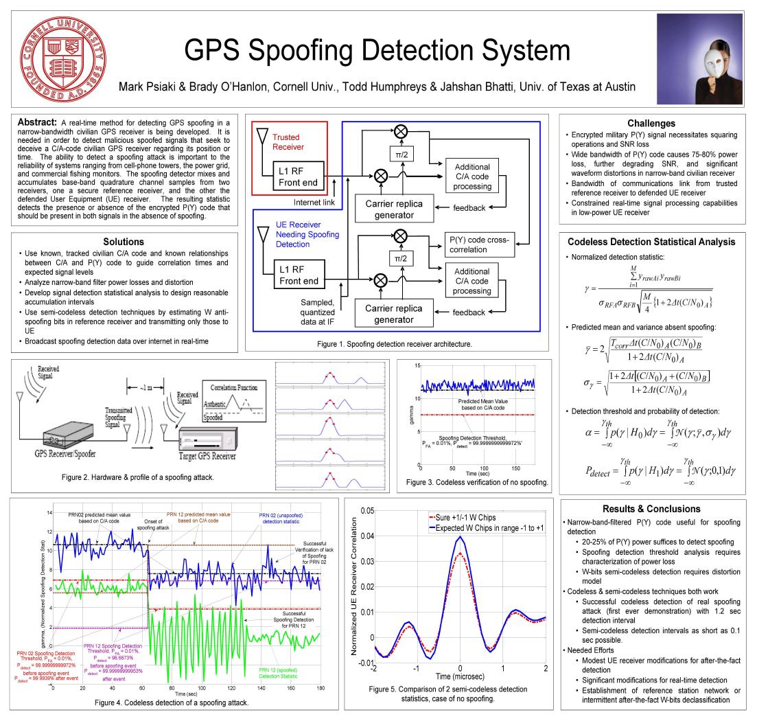
- GPS Spoofing Detection System A real-time method for detecting GPS spoofing in a narrow-bandwidth civilian receiver.
- Spoofing Civil GPS-Based Timing by Todd Humphreys (1.1M PDF)
- Assessing the Civil GPS Spoofing Threat (1.7M PDF)
- Coaxial Cable Delay by Jacques Audet, VE2AZX (137k PDF)
- Time Synchronization Attack in Smart Grid - Part 2: Cross Layer Detection Mechanism (926k PDF)
- A Simple Demonstration that the Global Positioning System (GPS) is Vulnerable to Spoofing (1.6M PDF)
- GPS Spoofing Countermeasures (222k PDF)
- On the Requirements to Successful GPS Spoofing Attacks (746k PDF)
- Security For and From GPS by Per Enge, Professor of Aeronautics and Astronautics - Stanford University (YouTube)
- Is Your TimeSpace Safe? - Time and Position Spoofing Opensourcely We have found a way to produce GPS spoofing with an extremely low-cost SDR device and both iPhone and Apple Watch could be affected. The map apps of iOS and Android can be cheated too, and you can even produce an Uber position spoofing, which make LBS apps vulnerable. Futhermore, the time information of smart devices could be easily cheated, since those devices rely heavily on GPS based timing or NTP service (also based on GPS timing). Additionally, we will examine other common positioning methods used by smart devices, such as iBeacon/BLE/Wi-Fi. We will give a demo on how we collect Wi-Fi Access Point SSID data, and then make a fake Wi-Fi environment to cheat Wi-Fi positioning system of Android. In the end, we will also give some suggestions in order to prevent such spoofing.
- Hunting GPS Jammers This presentation provides an introduction to the vulnerabilities of satellite navigation and timing systems and the ways in which these vulnerabilities have been exploited. First, the specific vulnerabilities of GPS-based systems are introduced – the main vulnerabilities of GPS are due to the very low signal strength of the satellite signals. The paper discusses the effect of RF interference on satellite navigation and timing systems and introduces some real examples of disruption caused by real interference events. (Slides)
- Low-Cost GPS simulator - GPS Spoofing by SDR It is known that GPS L1 signal is unencrypted so that someone can produce or replay the fake GPS signal to make GPS receivers get wrong positioning results. There are many companies provide commercial GPS emulators, which can be used for the GPS spoofing, but the commercial emulators are quite expensive, or at least not free. Now we found by integrating some open-source projects related to GPS we can produce GPS signal through SDR tools, e.g. USRP/bladeRF. This makes the attack cost very low. It may influence all the civilian use GPS chipset. In this presentation, the basic GPS system principle, signal structure, mathematical models of pseudo-range and Doppler effect will be introduced. The useful open-source projects on Internet will be shared with attendees.
- GPS-SDR-SIM GPS-SDR-SIM generates GPS baseband signal data streams, which can be converted to RF using software-defined radio (SDR) platforms, such as ADALM-Pluto, bladeRF, HackRF, and USRP.
- Spoofing a Multi-Band RTK GNSS Receiver with HackRF One and GNSS Jammer (PDF)
- Global Navigation Satellite System Repeater Disruption Eurosavage Patent EP1901084A1 (124k PDF)
- Spoofing Detection System for a Satellite Positioning System U.S. Patent 5,557,284 (539k PDF)
- Apparatus and Method for Providing a Deception Response System U.S. Patent 6,480,140 (49k PDF)
Other Related GBPPR Projects:
- Cellular Phone/GPS "Burst" Tracking Device Jammer
- GPS (L1) Jammer
- Device for Detecting GPS Receivers
- Simple GPS Jammer Using a Satellite Tuner
- Simple CW GPS Jammer
- GBPPR Homebrew Radar Experiments

