
Overview
Illegal aliens are using GPS devices (Mirror) to illegally invade the U.S. It's now time to fight back. Build several of these devices and flood the Mexico border to disable any GPS reception.
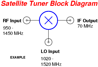
This GPS jammer is made from the parts of an old C-band analog satellite receiver. These are becoming hard-to-find, but they do show up at Goodwill / thrift stores from time-to-time. Normally, the tuner inside the receiver takes the incoming (downconverted) 950 - 1,450 MHz RF signal from the satellite dish's block converter and heterodynes it down to a lower frequency of 70 MHz. This 70 MHz signal is then further downconverted and finally demodulated for the required video and audio signals.
During the 950 - 1,450 MHz to 70 MHz conversion, the satellite tuner will generate what is called a Local Oscillator (LO) RF signal that is 70 MHz higher than the frequency being received. That is, when the tuner is tuned to C-band satellite channel 10, the tuner is actually receiving at 1,250 MHz (satellite downlink frequency of 3,900 MHz). The local oscillator frequency needed to convert the 1,250 MHz signal to 70 MHz is then 1,320 MHz (1,250 + 70 MHz). Most satellite tuners have a little bit of "play" in the local oscillator tuning, and they are capable of generating RF signals outside of their normal range. This means a satellite tuner can be turned into a simple L1 band GPS jammer by using it to generate a RF carrier at around 1,575.42 MHz.
Note that not every satellite tuner works on those exact frequencies. Some use an IF signal of 130 MHz or so and some will tune up to over 2,100 MHz They will all be quite similar though. Digital tuners can also be used, but their operation and construction makes them much more difficult to work with.
Block Diagram & Schematic
Pictures
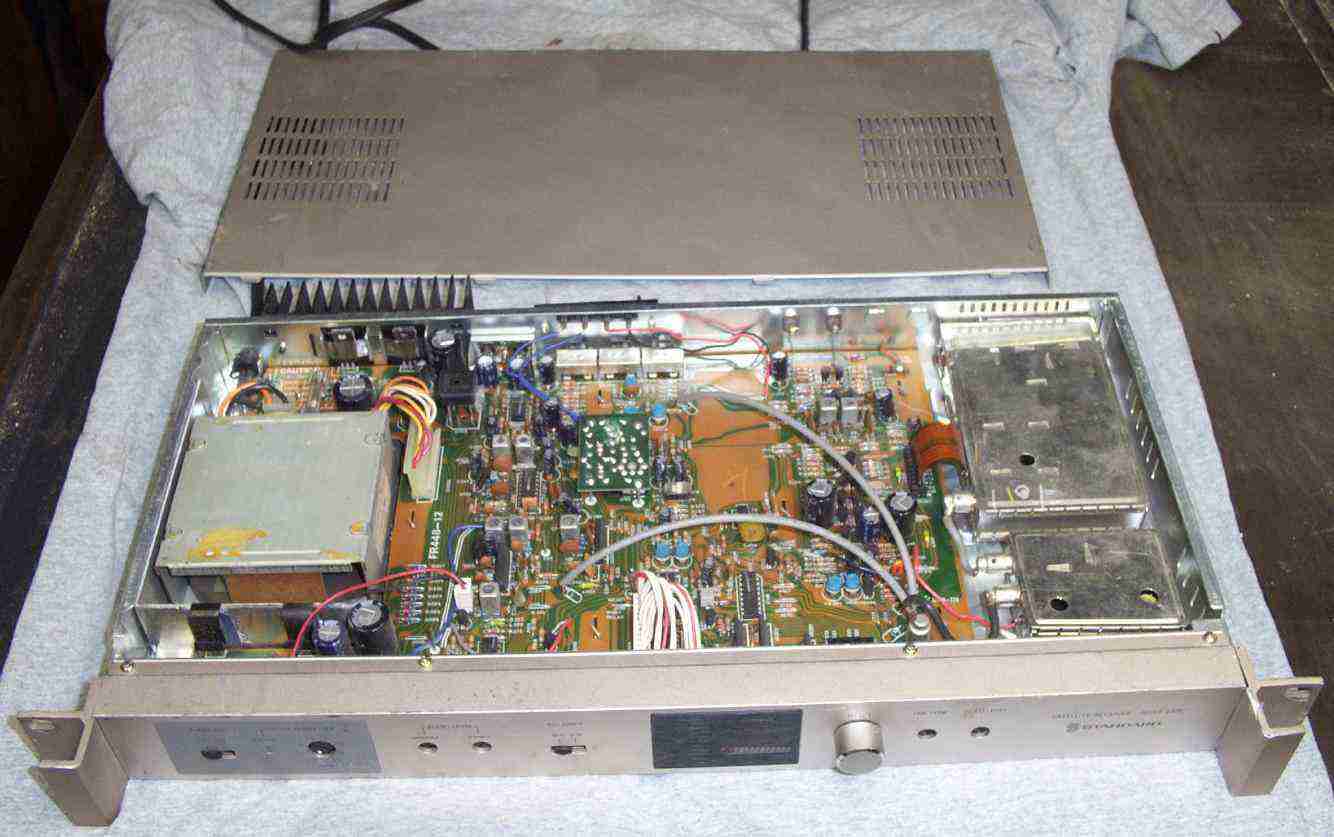
Overview of the satellite receiver used for this project. It is a rack-mount "Standard Satellite Receiver, Agile 24PC". The power supply is on the left, the channel control and demodulator section is in the middle, and the tuner is big silver box on the right.
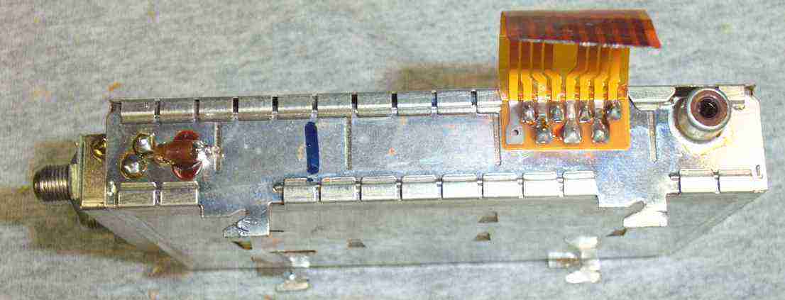
Close up picture of the tuner. The 950 - 1,450 MHz RF input from the block converter goes into the F connector on the left. The other F connector is just a feed-through. The tuner's power and voltage control lines go in via the ribbon cable. The tuner's IF output is via the RCA jack on the right.
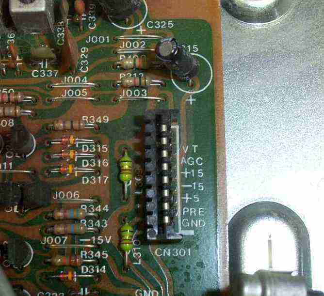
Close up of the ribbon cable connections. VT is the Voltage Tune line, AGC is the Automatic Gain Control, +15 is +15 VDC, -15 is -15 VDC, +5 is +5 VDC, PRE is the Prescaler Output, GND is Ground.
Only the +15, VT, and GND connections will be needed. The tuner will operate at +12 VDC if +15 VDC isn't available.
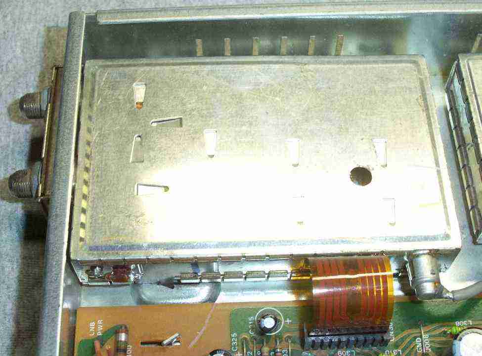
Connection view of the satellite tuner. The little neon light bulb is for dissipating static electricity on the block converter's voltage bias line. The ribbon cable can be unsoldered.
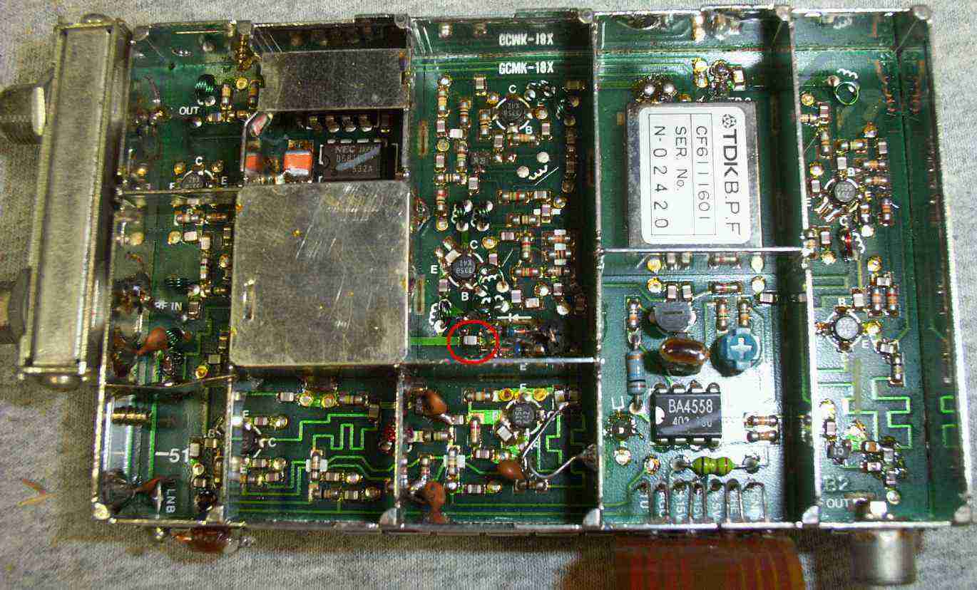
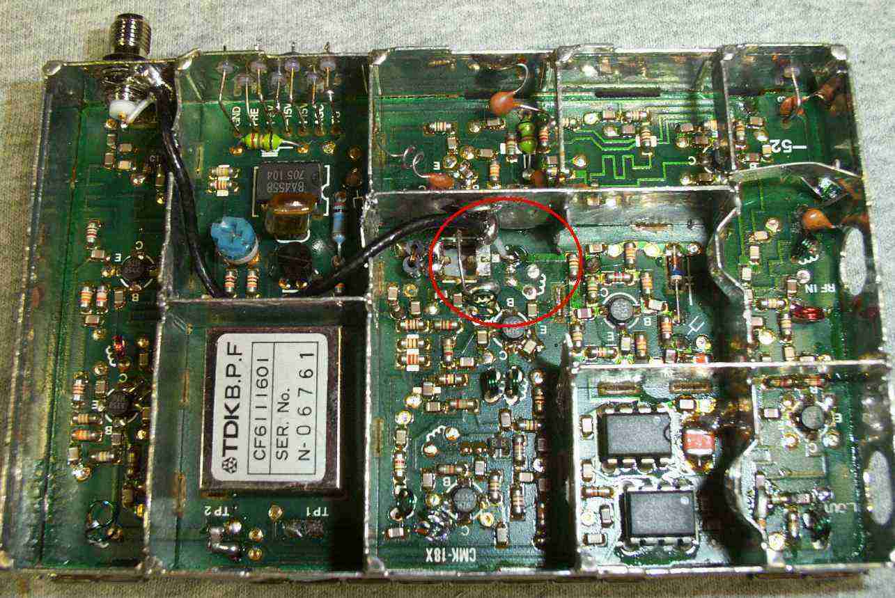
Inside view of an unmodifed satellite tuner. 950 - 1,450 MHz RF input is on the left. Under the shielded box are the local oscillator components. Next to that, the section with the two back-to-back diodes is where the RF and LO signals are mixed to form the new 70 MHz IF signal. The box with the "TDK" logo on it is a bandpass filter for the IF. The IF signal is then further amplifed and sent to the RCA jack on the bottom right.
The little red circle around the capacitor is where the LO signal should be tapped. You'll need to remove the capacitor, and run a little piece of coax from the local oscillator line to an external RF connector.
Inside view of a modified satellite tuner. The LO signal is routed via a short piece of RG-196 coax to a SMA connector mounted on the side of the case. The shield has been removed for a better view. The F connectors have been removed to make the case smaller.
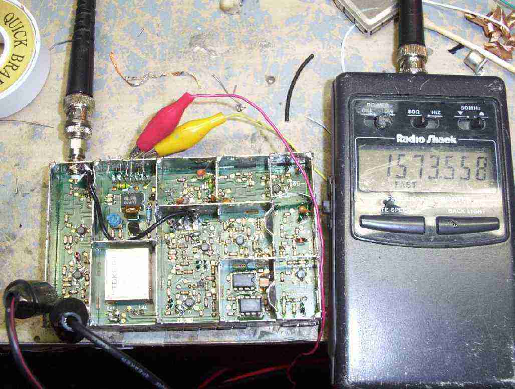
Test setup. The frequency counter is reading "1573.558 MHz". Anywhere near 1,575 MHz is usually good enough to jam GPS signals.
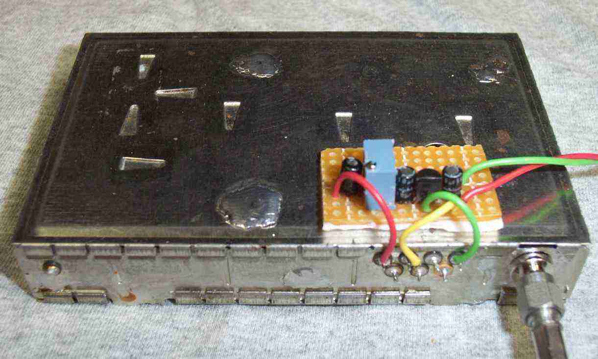
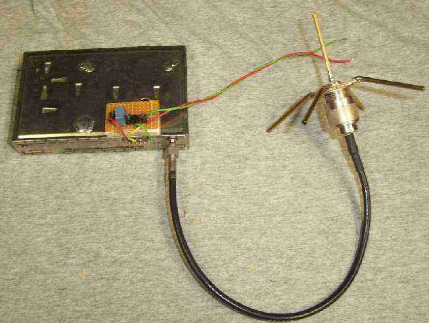
Completed voltage regulator and voltage tune potentiometer control board. +12 VDC power input from a car battery is on the right side. The 78L05 is in the middle and the 10 kohm potentiometer is on the left. The RED wire on the tuner is for the Voltage Tune line, the YELLOW wire is for the +12 VDC Input, and the GREEN wire is Ground.
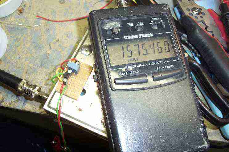
Test setup showing the completed voltage regulator and potentiometer control board mounted to the tuner with double-sided tape. The frequency counter is reading "1575.46 MHz".
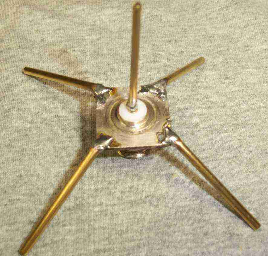
Homebrew GPS (1,575 MHz) ground plane antenna. Each element is made from brass tubing and is about 1/4-wavelength (47 mm) long. Be sure to use a N connector with Teflon dielectric material, otherwise it will melt when you solder it. Bend the ground plane elements at 45° angles when finished.
You're gonna die!
Datasheets / Notes
- Higher resolution pictures and the original project article are available in GBPPR 'Zine Issue #17
Other Related GBPPR Projects:
- Cellular Phone/GPS "Burst" Tracking Device Jammer
- GPS (L1) Jammer
- Device for Detecting GPS Receivers
- Simple CW GPS Jammer
- GPS Delay Spoofing Experiments