The main component in a radar system that determines the RF pulse length is a passive circuit called the Pulse-Forming Network (PFN). This circuit is essentially a lumped-component inductor/capacitor version of a long piece of coaxial cable, in that is has a delay time and impedance. The number of inductor/capacitor sections in the pulse-forming network determines the overall pulse length, usually a microsecond or so. The ratio of inductor/capacitors also sets the impedance of the PFN. The impedance will stay the same, regardless of the number of L/C sections, provided the inductors/capacitors maintain the same value.
When operating, the PFN is charged to a high-voltage DC potential (we'll be using 2,000 volts) and is quickly discharged to ground using a thyratron or other type of high-speed trigger. Since the PFN is connected in series with the pulse transformer's primary, the discharge induces a large voltage spike equal to one-half the charging voltage in the pulse transformer's primary windings. This voltage pulse is equal in length to the PFN's delay time. The voltage pulse is further stepped-up via the pulse transformer's secondary winding and is finally applied to the magnetron's cathode. The PFN's impedance is also stepped-up via the pulse transformer to help match the magnetron's operating impedance, which is usually around 1,200 ohms. Impedance matching helps to keep the transmitted RF pulse from being "deformed." Pulse transformer operation will be covered in better detail in an upcoming article.
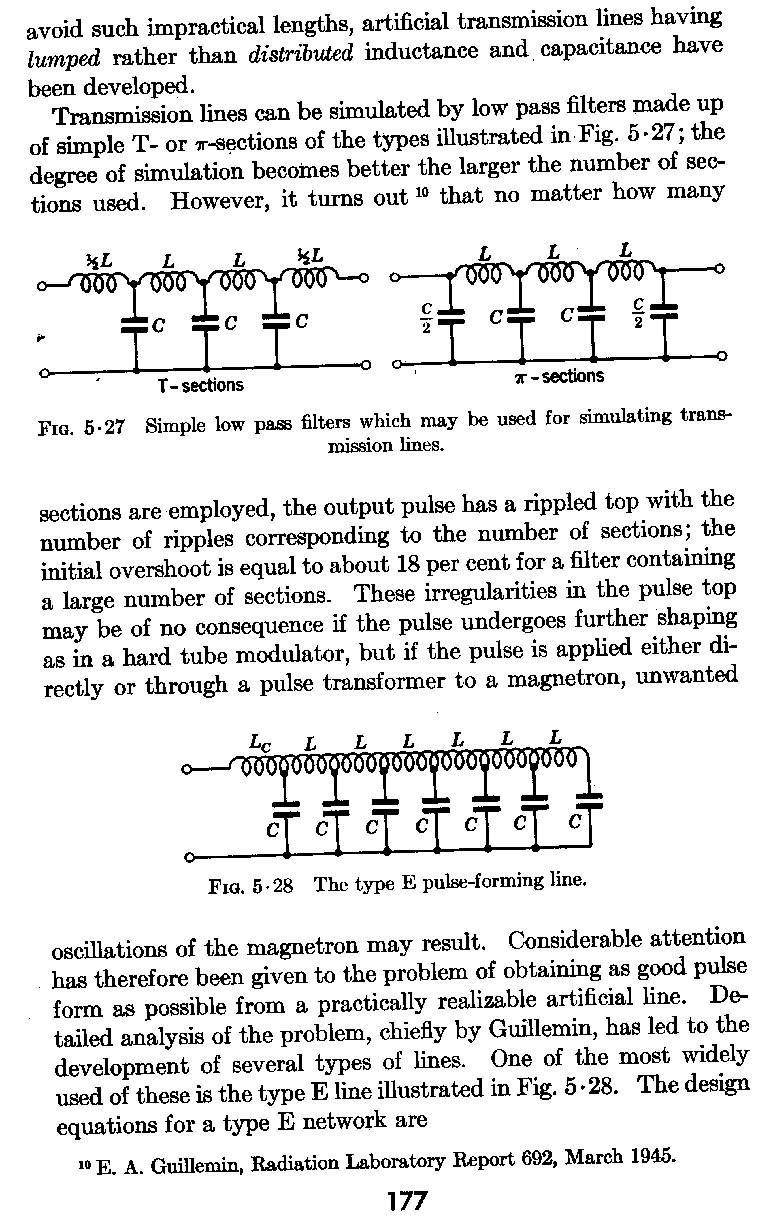
The PFN we'll be using is the most widely used version, the type-E pulse-forming transmission line. This consists of a single ferrite core with a number of winding taps for the capacitors.
Example:
Using five 10 µH inductors and five 1,000 pF capacitors; you would have a PFN with a pulse width of 1 µS and an impedance of 100 ohms.
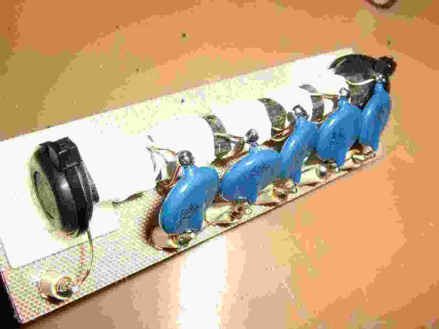
Parts for our homebrew pulse-forming network.
The main L/C components are a 10 mm diameter ferrite rod antenna from an old "auto-setting" clock (C-MAX CMA-60-100 or similar), and five 1,000 pF / 4 kV capacitors.
The inductors will be wound on the ferrite rod using #22 enameled wire.
The ferrite rod will be attached to an optional fiberglass base using two rubber grommets to isolate and secure it.
The white square things are adhesive-backed cable tie mounts.
Optional solder-terminals will be used for holding one end of the capacitors.
This is all a total hack, and I'm not even sure it's correct. I've never even seen a PFN in real-life. Seriously...
Forming the inductors.
To help secure the windings, wrap the ferrite rod with some double-sided sticky tape.
Wind about 12 turns of #22 enameled wire to make a 10 µH inductor. You may need to tweak the number of required turns, depending on the composition of the ferrite rod.
Make the five inductor sections, as shown above, then secure the windings with some Q-dope or other type of glue.
Be sure to leave a little space on the ferrite rod to attach the grommets.
The PFN will generate high-currents, but only for a short time, so it pays to use heavier gauge wire.
When finished, secure and wrap the inductors with a few turns of Teflon plumbers tape.
Attach the ferrite rod to the base by wrapping zip ties around the grommets and attaching them to adhesive-backed mounting points on the base.
Mounting the PFN on a separate base is optional, but should help to make it easier to swap out if you need to change the radar's pulse length.
Completed pulse-forming network.
One lead of the high-voltage 1,000 pF capacitors is soldered to a terminal, the other is supported by the inductor windings.
The high-voltage DC charging positive input is via the terminal on the lower-left. The output is via any other terminal.
The entire PFN assembly will be mounted on stand-offs to allow for high-voltage isolation.
A very detailed description of how pulse-forming networks operation (and other radar operations) is available in the U.S. Army Aviation Course - Subcourse MM5005: Radar Transmitter manual.
This manual is available online at:
http://www.tpub.com/content/armymunitions/mm50058/index.htm