Dataradio Gemini G3 UHF Radio Modem Experiments |
EXPERIMENTAL |
Overview
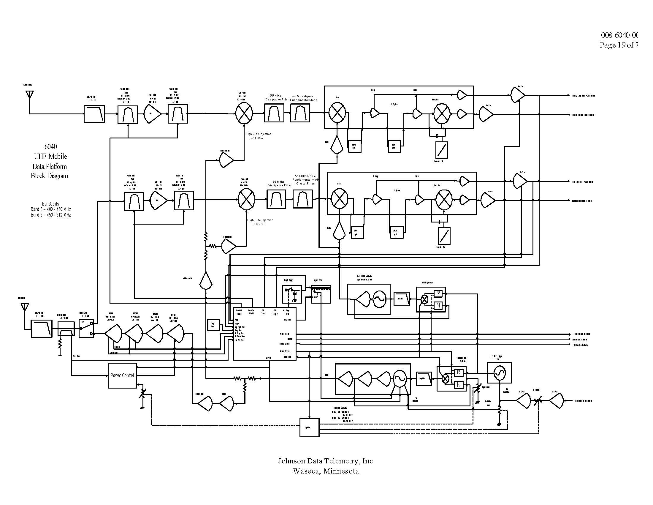
The Dataradio Gemini G3 is a UHF (450-512 MHz) mobile radio modem housed in an aluminum cabinet and integrated Ethernet connection. It comprises a transceiver with a second space-diversity receiver, a variable 2-50 watt RF power amplifier, and a Gemini Control Unit (GCU). The modem used on the GCU is based around a Motorola DSP56303 Digital Signal Processor (DSP) operating at an oscillator frequency of 12.228 MHz. The main modem function is to convert the digital data into analog filtered waveforms used to modulate the transceiver with DGFSK (Differential Gaussian Frequency Shift Keying). The modulation scheme is either 2-level FSK (DGMSK), 4-level FSK (xRC4FSK), or 8-level FSK modulatio depending on the datarate.
The transceiver and the DSP modem interface uses five analog signals:
- XCVR_TXMOD (TXA, outgoing audio signal)
- XCVR_RX1 (RXA_1 incoming audio signal)
- XCVR_RX2 (RXA_2 incoming audio signal)
- CH0 (main receiver RSSI_1)
- CH1 (diversity receiver RSSI_2)
The transceiver and the diversity receiver audio incoming channels are processed by a PCM3002 CODEC using a sampling frequency of 48 kHz. It provides dual filtered audio bi-directional channels, with separate pairs of A/DD/ A converters The DSP modem circuit processes both Receivers RSSI signals from the transceiver using U12 (AD7811), a 10-bit serial A/D converter.
The latest certification EOTGPDA has been granted to Dataradio Inc on 12/04/2001 for its Gemini/PD radio modem. Gemini/PD is comprised of the Dataradio COR Ltd. (DRL) Mobile Data Platform (MDP) UHF (403 MHz-512MHz) Transceiver with the Dataradio Inc Gemini Modem. Dataradio Inc does the final assembly and markets the Gemini/PD unit. The certificate, comprising its several Class II permissive changes already underwent, has been granted for: - 8K60, 15K0 and 15K3F1D for respectively 9.6, 16.0 and 19.2kbps DGMSK Differential Gaussian Minimum Shift Keying digital modulation - 16K8,15K6,16K0, 8K17 and 8K67F1D for respectively 32.0, 25.6,19.2,16.0 and 14.4kbps xRC4FSK family of Raised Cosine 4-level Frequency Shift Keyinga
The Gemini modem generates 2-level Differential Gaussian Frequency Shift Keying (DGFSK) and 2n-level family Raised Cosine Frequency Shift Keying. (xRC nFSK). 2-level DGFSK and 4-level xRC has been granted with the certificate EOTGPDA. This measurement concerns only 8-level xRC (raised cosine family) modulation, its description follows. This digital modulation scheme is produced by the main CPU in conjunction with the DSP. The main CPU processes incoming binary data, applying Forward Error Correction (FEC), interleaving and scrambling, and from it generates an NRZ signal that is fed to the DSP processor for encoding and pulse shaping. The DSP processor assigns to every incoming group of three bits a symbol recorded in a level of frequency shift. The mapping follows a Gray scheme:100-highest positive frequency, 101-next highest positive, etc, to 000-lowest negative, resulting signal being a 8-DC level digital. This 8-level signaling transmits three information bits per symbol (baud) which yields a bit rate of three times the on-air baud rate, hence the 28.8 kbps references in the Installation Guide correspond to a transmitter baud rate of 9600 baud. That digital signal is digitally filtered (Squared Root or pure Raised Cosine pulse shaping with roll off factor 0.4) by the DSP then fed to the CODEC for digital to analogue conversion. This xRC8FSK wave shape applied to the FM modulator will then produce a compact RF spectrum, when using proper frequency deviation, to fit inside the restrictive masks inherent to the intended channel bandwidth. The transmitter deviation level and digital filter cutoff frequency (which is based on the raised cosine filter equation) are set according to the bit rate selected and channel bandwidth as shown in page 10.
The transmitter deviation level and digital filter cutoff frequency (which is based on the raised cosine filter equation) are set according to the bit rate selected and channel bandwidth as follows: Bit rate Baud rate Raised Cosine filter s 3dB cut-off frequency Deviation 48000 b/s 16000bauds 8.0 kHz ± 5.1 kHz 43200 b/s 14400bauds 7.2kHz ± 5.2 kHz 24000 b/s 8000bauds 4.0 kHz ± 2.5 kHz 21600 b/s 7200bauds 3.6 kHz ± 3.9 kHz
Pictures
Click for higher resolution.
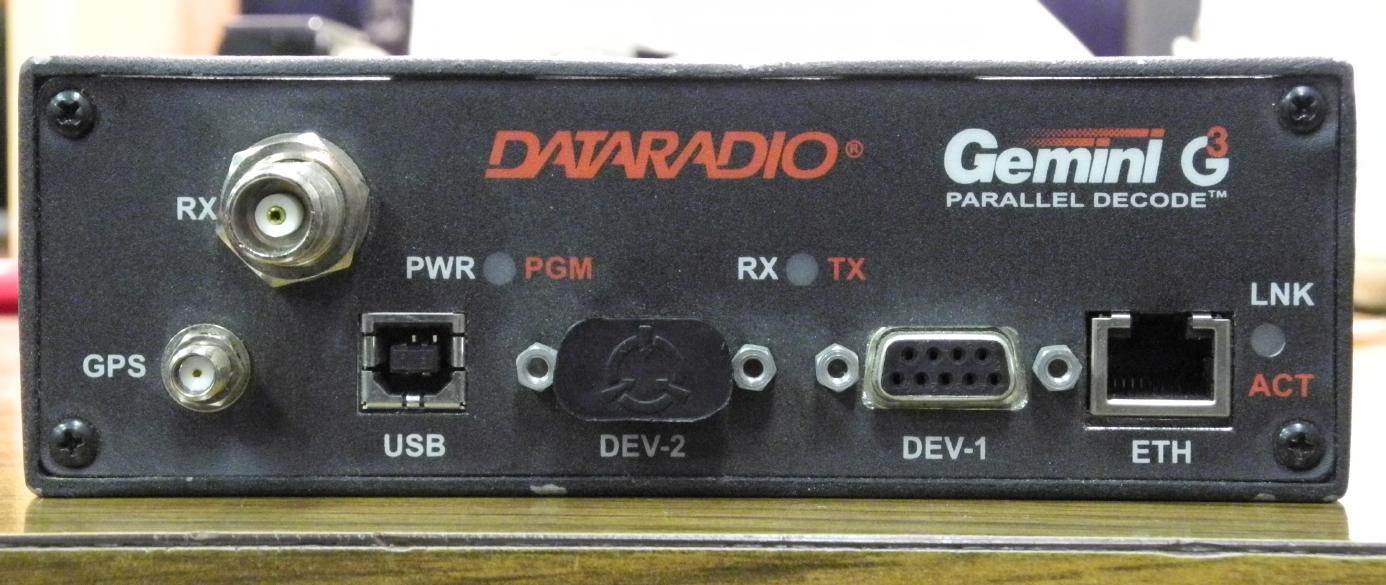
Front-panel overview of a Dataradio Gemini G3 UHF Radio Modem (FCC ID: EOTGPDA).
The TNC jack is for the diversity receive antenna. This antenna would be mounted about 5/8ths wavelength away from the main antenna connection (real-panel TNC). This connection is for receive only and doesn't transmit.
SMA jack is for a powered GPS antenna.
USB connector appears to be unused.
The two DB-9s (DEV-2 & DEV-1) are for interfacing with RS-232 devices.
The RJ-45 Ethernet connection is on the lower-right.
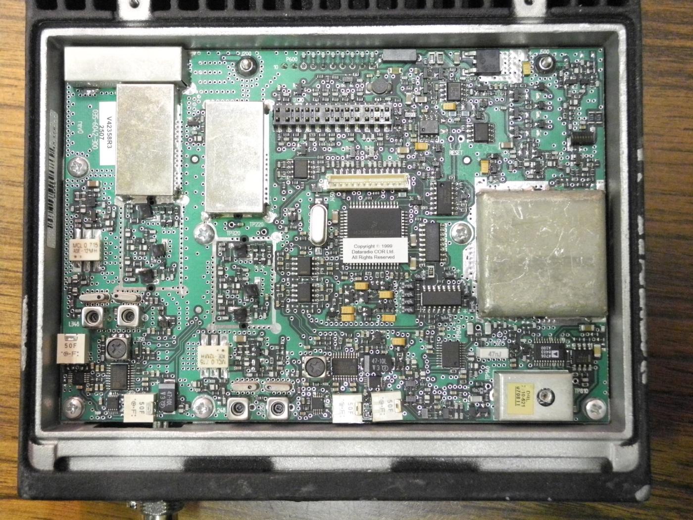
Overview of the top circuit board. (Bottom View)
The dual receivers are along the left-hand side. Under the shields are most likely the receive filters.
The large shield on the right-hand side is the main VCO with the Philips SA7026 fractional-N, dual frequency synthesizer (50 kHz reference) to the lower-left.
The device with the trimmer access port on the lower-right is a Temperature Compensated Crystal Oscillator (TCXO). I think it's 17.5 MHz.
Pinout for the 12-pin auxillary/programming board connector (J450, white):
- AUX TXD
- AUX RXD
- AUX FLASH ENABLE
- AUX RF ENABLE
- FUSED BATTERY
- AUX PTT REQUEST
- AUX TEST
- GROUND
- OUTPUT 1
- TRANSMIT MODULATION
- MAIN RECEIVER DEMOD
- DIVERSITY RECEIVER DEMOD
Pinout for the 24-pin user/modem interface board connector (J400):
- DIGITAL GROUND
- MODEM TXD
- MODEM RXD
- XCVR FLASH ENABLE
- MODEM DATA INPUT
- MODEM DATA OUTPUT
- MODEM CLOCK
- XCVR SELECT / OUTPUT 3
- XCVR BUSY OUTPUT / OUTPUT 2
- OUTPUT 1
- OUTPUT / INPUT 1
- OUTPUT / INPUT 2
- OUTPUT / INPUT 3
- OUTPUT / INPUT 4
- XCVR PTT REQUEST
- XCVR ENABLE
- IGNITION SENSE OUTPUT
- FUSED BATTERY
- ANALOG GROUND
- TRANSMIT MODULATION
- MAIN RECEIVER DEMOD
- MAIN RECEIVER RSSI
- DIVERSITY RECEIVER DEMOD
- DIVERSITY RECEIVER RSSI
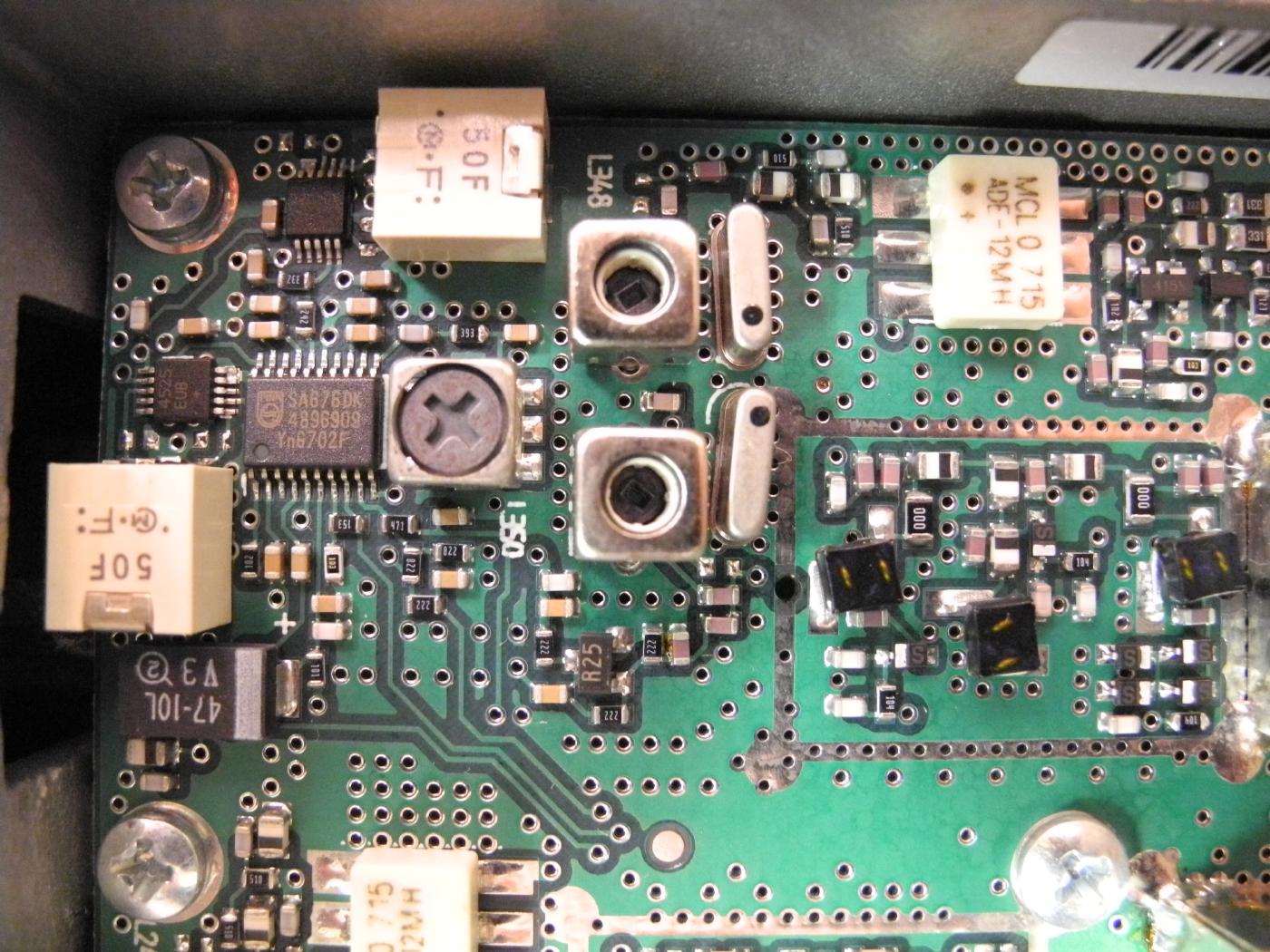
Closeup view of one of the receive sections.
The Gemini's use two seperate receivers with two receive antennas to minimize data loss due to polarization mismatches or fading.
The 1st IF frequencey is 55 MHz and is filtered via 4-pole crystal filters.
The 2nd IF frequency is 450 kHz and is filterd via those Murata IF filters.
A Philips SA676 is used for the 450 kHz IF FM demodulation and limiting. Baseband data output is essentially in the "audio" range.
Two Mini-Circuits ADE-12MH mixers are used for the receive mixing.
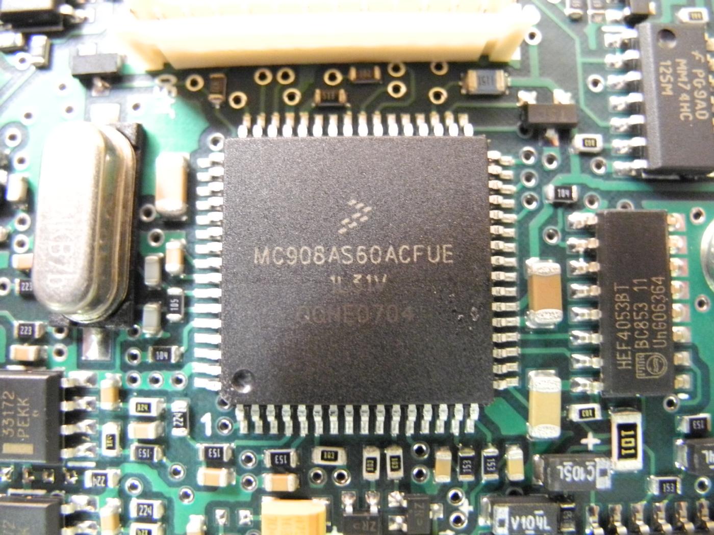
Freescale MC908AS60ACFUE 8-bit microcontroller.
The clock oscillator to the left is 4.9152 MHz.
The microcontroller controls the VCO synthesizer, adjusts the Gemini's front-end preselector filters, and controls transmit power to maintain equal power, deviation, and modulation flatness across the band.
There are numerous test points and headers across the board.
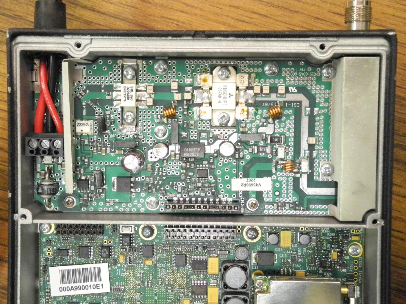
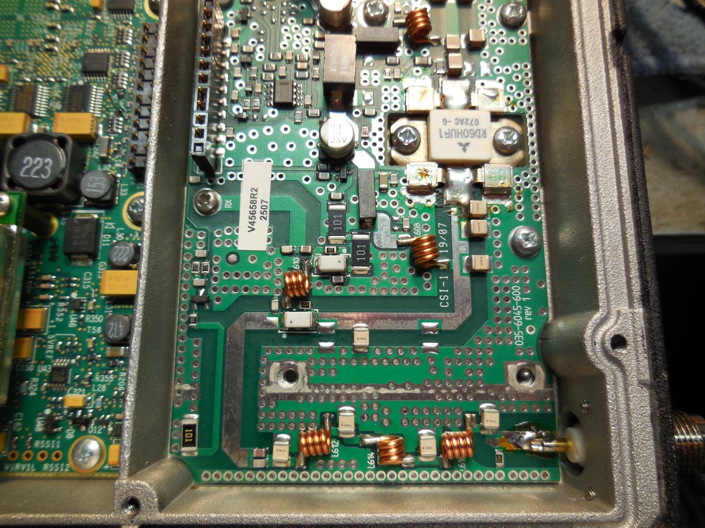
Overview of the RF power amplifier.
Pinout for the 10-pin PA board connector (P600):
- RAW BATTERY
- IGNITION SENSE
- TRANSMIT ENABLE (Pulls the power control amplifier out of saturation to allow PA to reach set RF output level)
- POWER CONTROL
- PA TEMP SENSE (Thermistor next to final PA transistor)
- FORWARD POWER SENSE
- TRANSMIT PRE-ENABLE (Prepares the RF board for transmit, biases the pre-driver and driver, and sets antenna switch to TX)
- PA CURRENT SENSE (Voltage drop through current sense resistor)
- GROUND
- GROUND
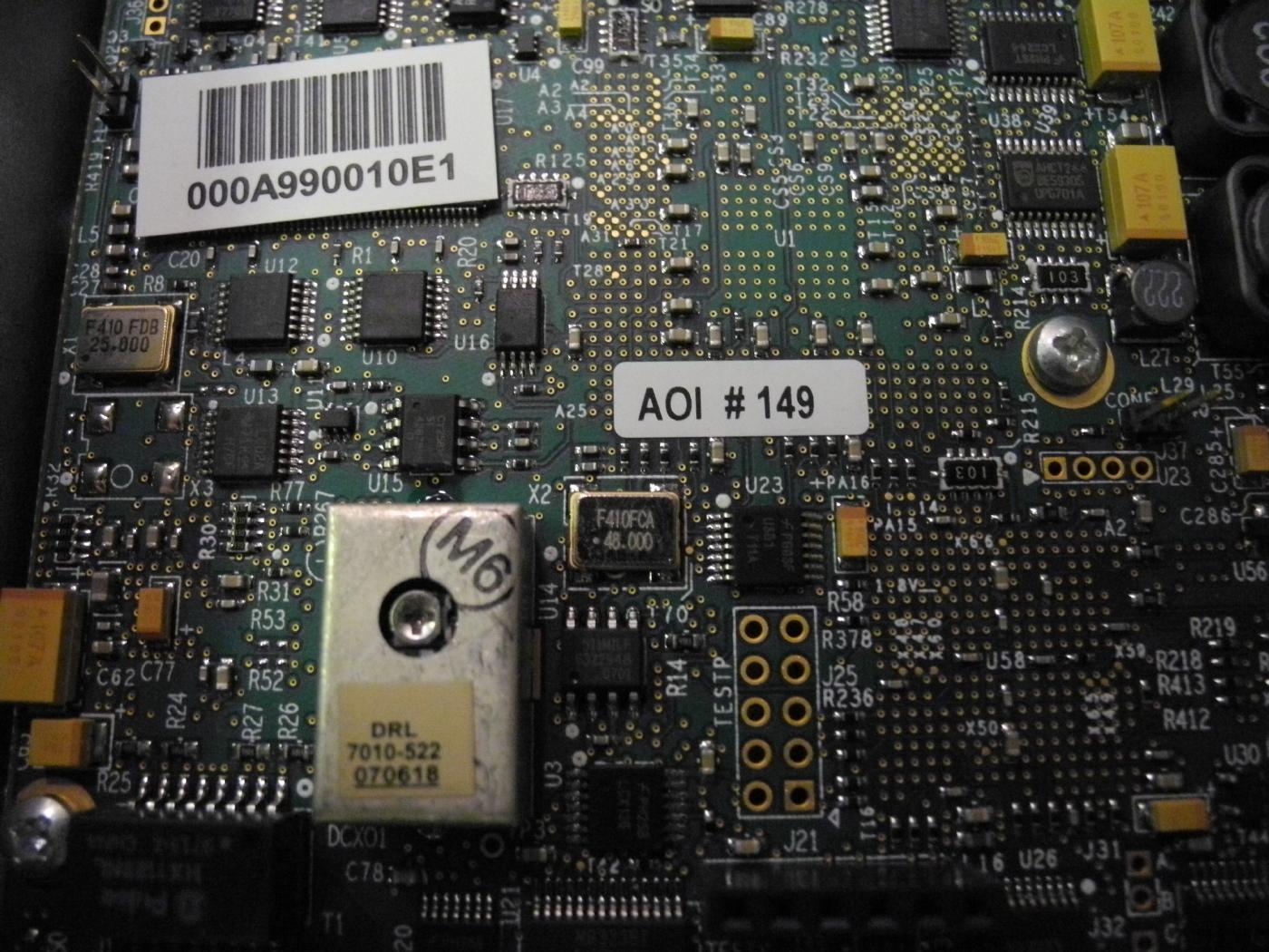
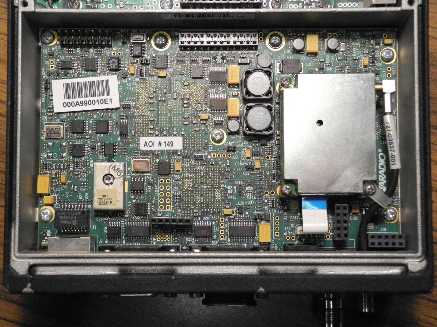
Overview of the lower circuit board. (Bottom View)
The module on the right-hand side is Ashtech G8 GPS receiver.
The G8 supports two TTL serial communication ports; one of which is used to interface to the GCU. The receiver outputs up to one GPS based position information per second serially at 4800 bps. The G8 processes signals from the GPS satellite constellation to provide real-time position, velocity, and time measurements. The G8 receives GPS satellite signals via an external active GPS (L1) antenna. The DGPS corrections if used, will be input into to the GPS receiver via the GCU.
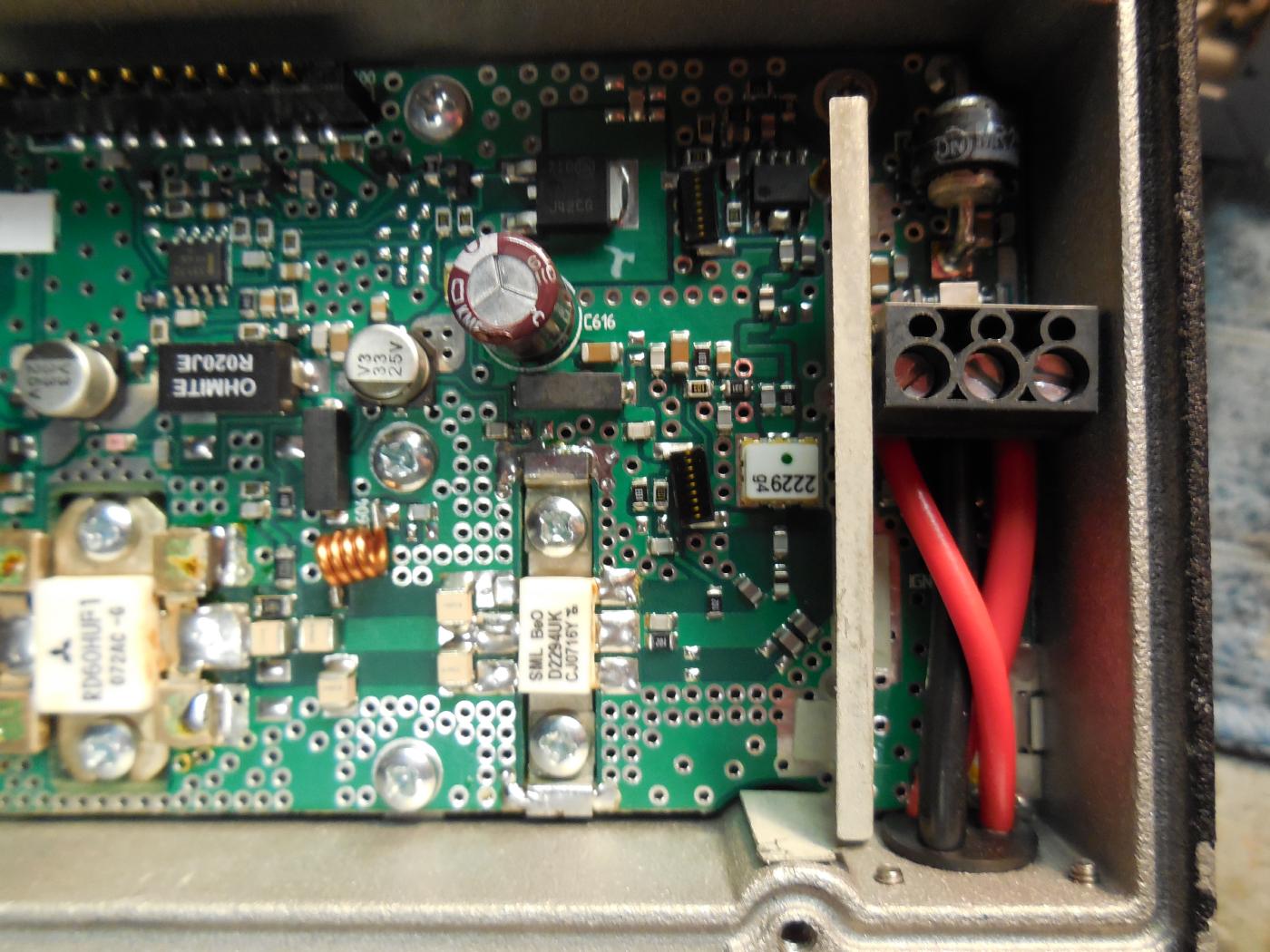
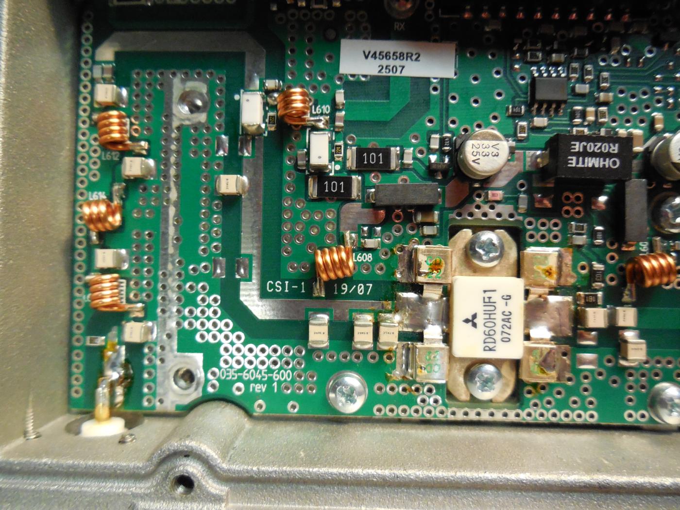
Final RF power amplifier transistor is a Mitsubishi RD60HUF1.
It'll hit 60+ watts if you really push it...
The pre-drivers are a SemeLAB D2294UK and SemeLAB D2229UK.
Notes & Links
- The default encryption passphrase appears to be: Dataradio
- Change RF and Ethernet MAC addresses in psa.rc?
- CalAmp Mobile Data Series Bought Dataradio Inc.
- Dataradio Gemini Configuration Screens Raw HTML configuration file grab. (Main Config Screen)
- Dataradio Gemini G3 Radio Modem User Guide - v3.01 (2.4M PDF)
- Dataradio Gemini G3 Radio Modem Installation Guide - v1.00 (184k PDF)
- Dataradio Gemini/PD Radio Modem Installation Guide - v1.44 (174k PDF)
- Dataradio Gemini/PD+ Radio Modem Installation Guide - v1.06 (177k PDF)
- Gemini/PD Radio Modem Description of Circuitry and Block Diagrams FCC ID: EOTGPDA (116k PDF)
- Gemini/PD Radio Modem Component List FCC ID: EOTGPDA (23k PDF)
- Gemini/PD Radio Modem Schematics FCC ID: EOTGPDA (315k PDF)
- Engineering Exhibit in Support of Certification FCC Form 731 for the Mobile Data Platform Transceiver With the Dataradio Gemini/PD Modem FCC ID: EOTGPDA (1.3M PDF)
- Philips SA676 FM IF System (76k PDF)
- Philips SA7026 1.3 GHz Dual PLL Synthesizer (236k PDF)
- Ashtech G8 GPS OEM Board Reference Manual (2.7M PDF) (Interface Summary)
Knowledge is Power