This is a collection of Polytec board photos from items I own. Here is picture collection #1 of boards from the Internet.
Polytec CLV Card DIN Connector Pin-Out:
DIN 41612 / IEC 60603-2 Connectors / Type M Male ERNI Part No. 594160 / 40 Pin + 4 Coax / Class 2 When viewed "parts side" up: Top Row: C Middle Row: B - Unused Bottom Row: A C07: +16 VDC C08: Ground C09: -16 VDC C10: C11: -5 VDC C12: C13: Signal Input? C14: C15: C16: C17: C18: C19: C20: C21: C22: C23: C24: C25: Ground C26: +5 VDC A07: +16 VDC A08: Ground A09: -16 VDC A10: A11: -5 VDC A12: A13: A14: A15: A16: A17: A18: A19: A20: A21: A22: A23: A24: A25: Ground A26: +5 VDC |
CLV-2000 Vibrometer Controller
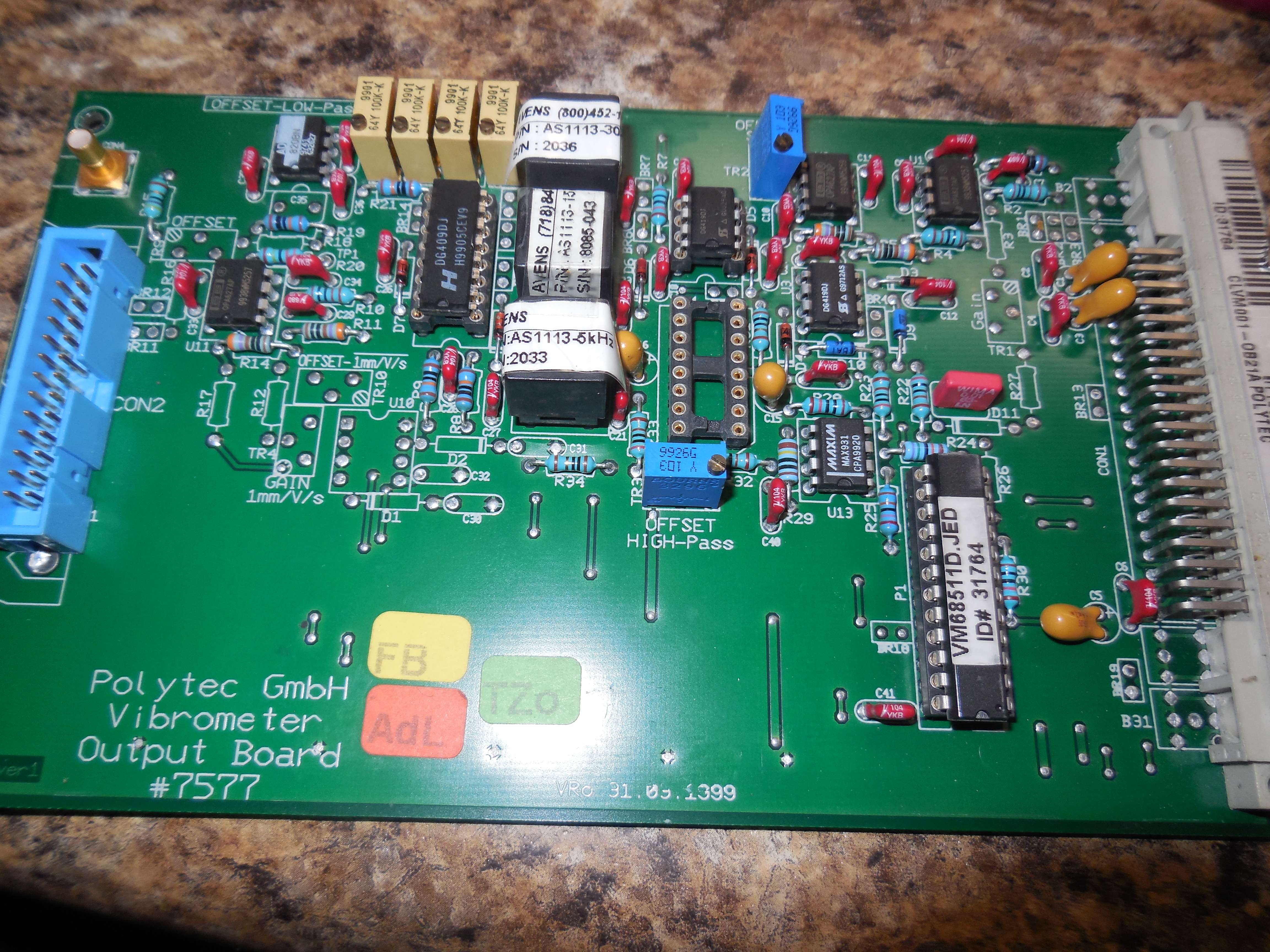
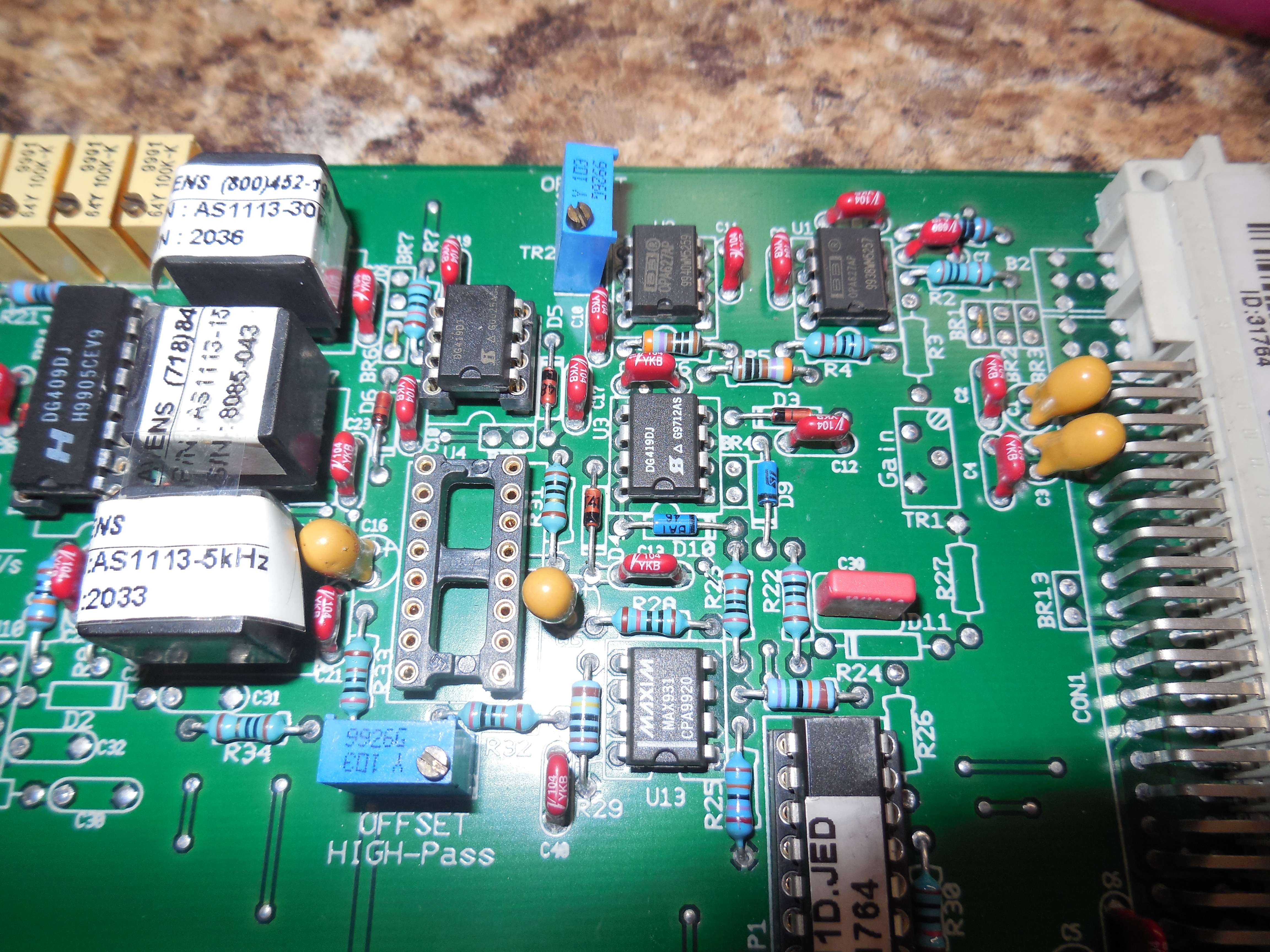
CLV-M001 Output Module
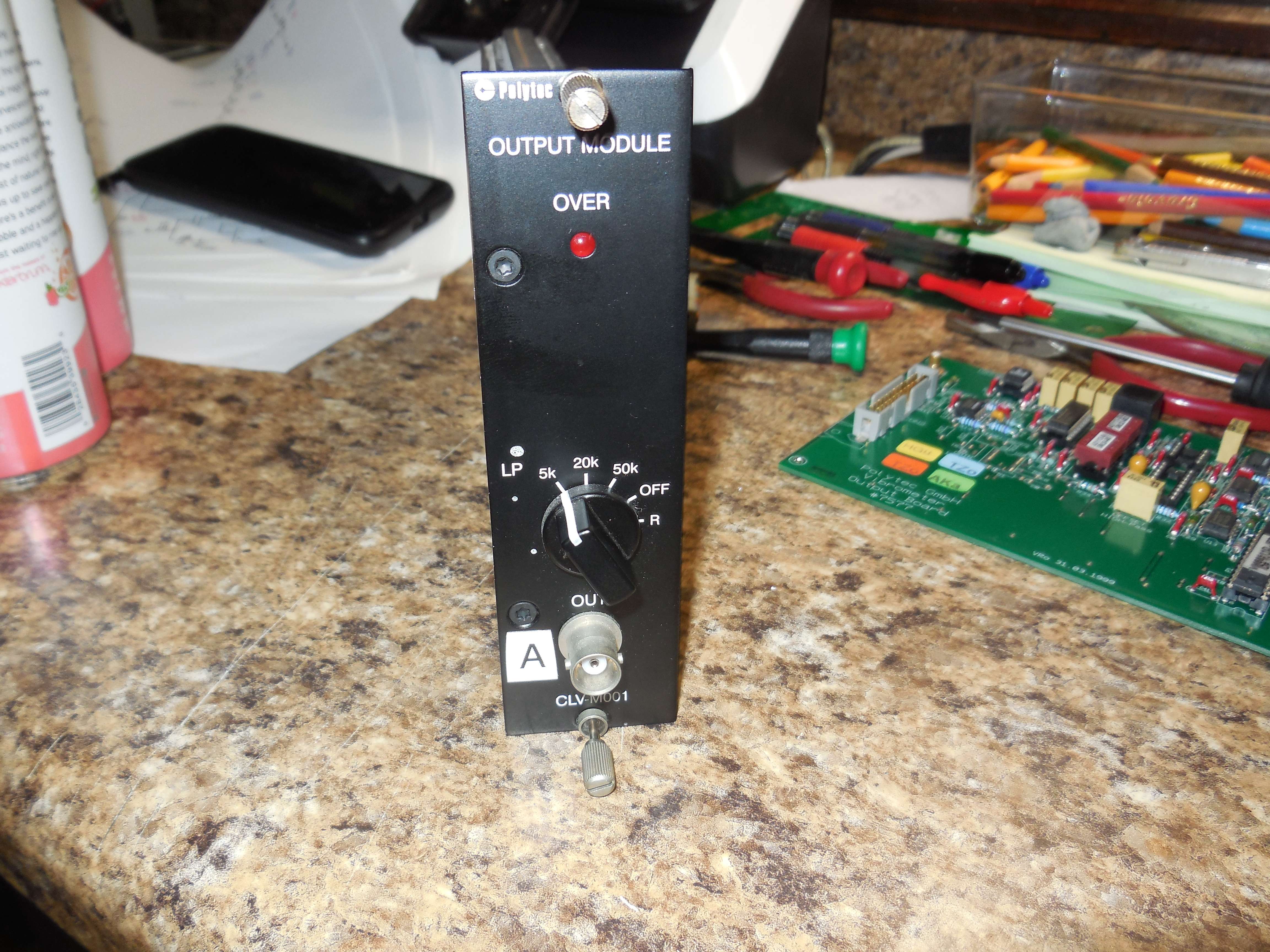
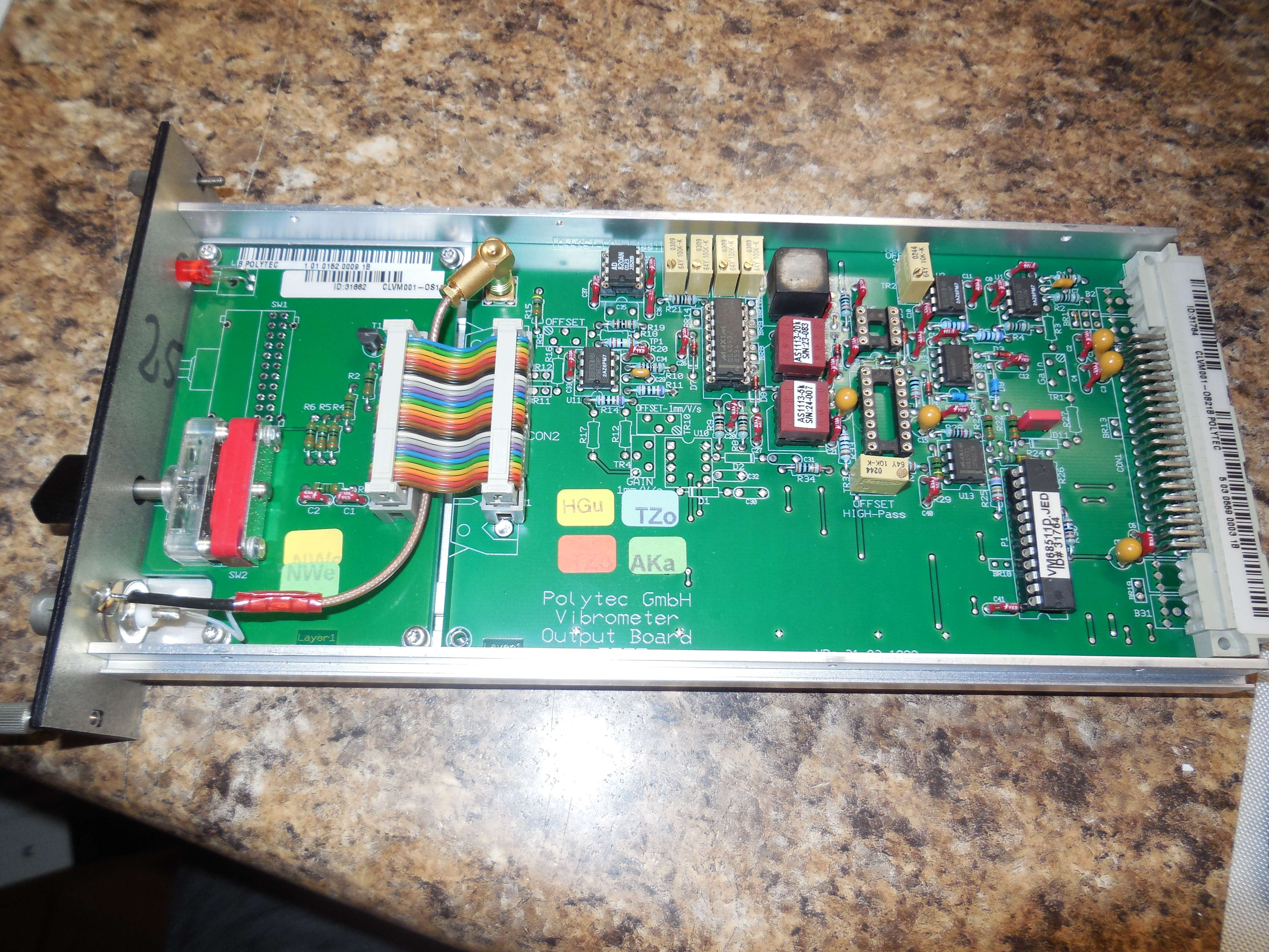
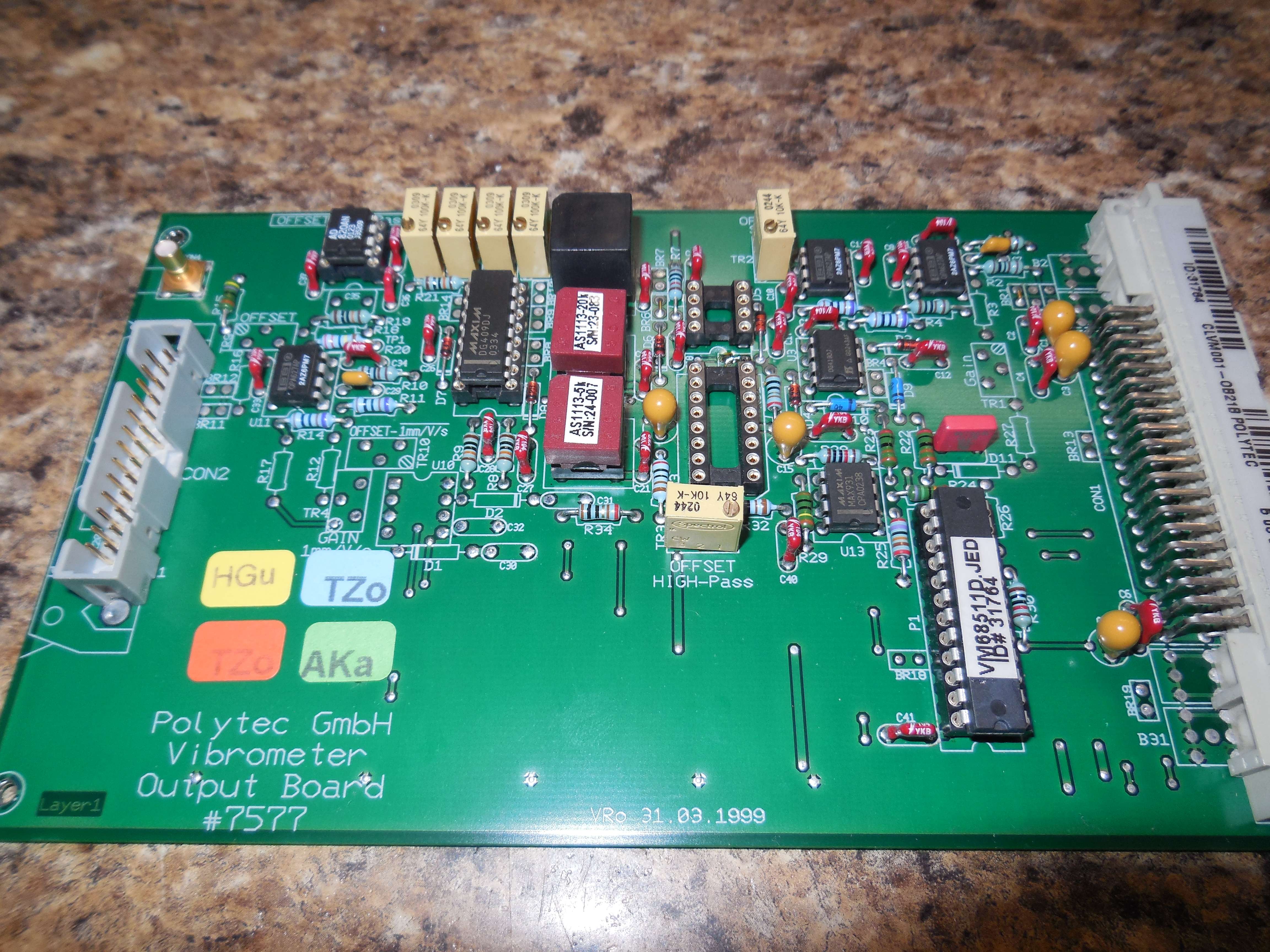
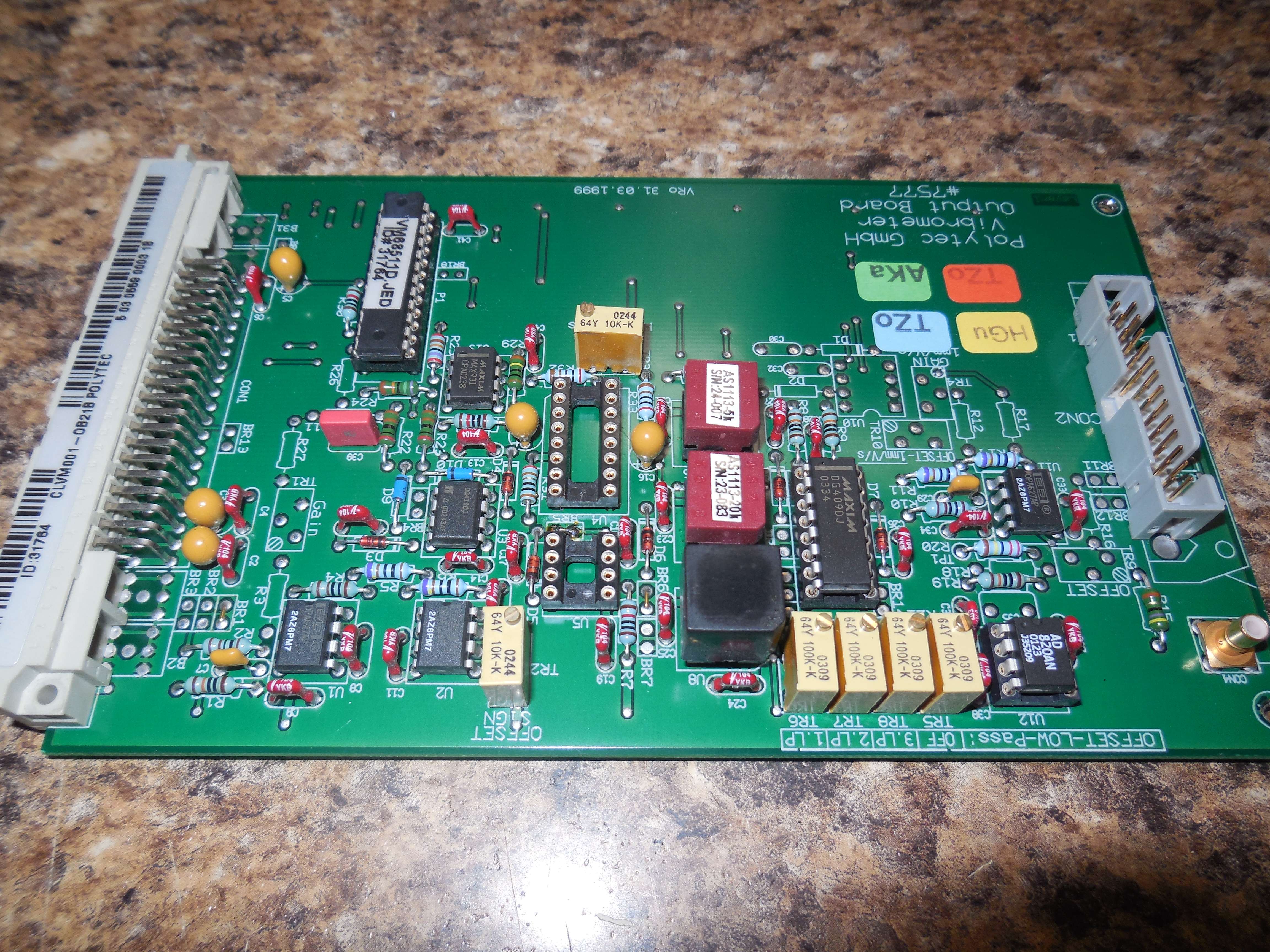
AD820A, MAX931, DG409, DG419, OPA627, Avens low-pass filters.
The Avens AS1113 low-pass filters are "all-in-one" devices which are switched in via the front-panel selector switch (5 kHz, 20 kHz, 50 kHz, off) .
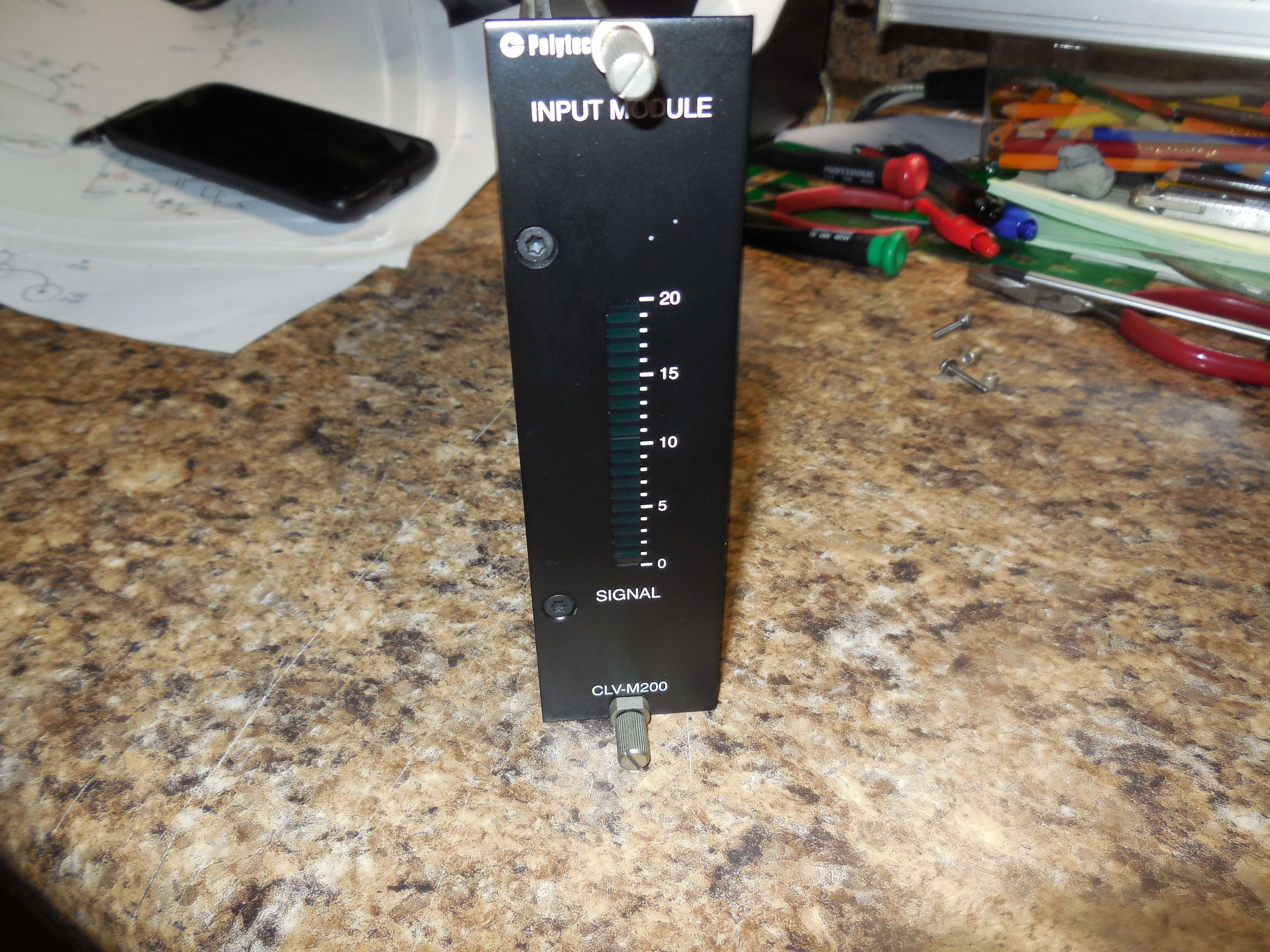
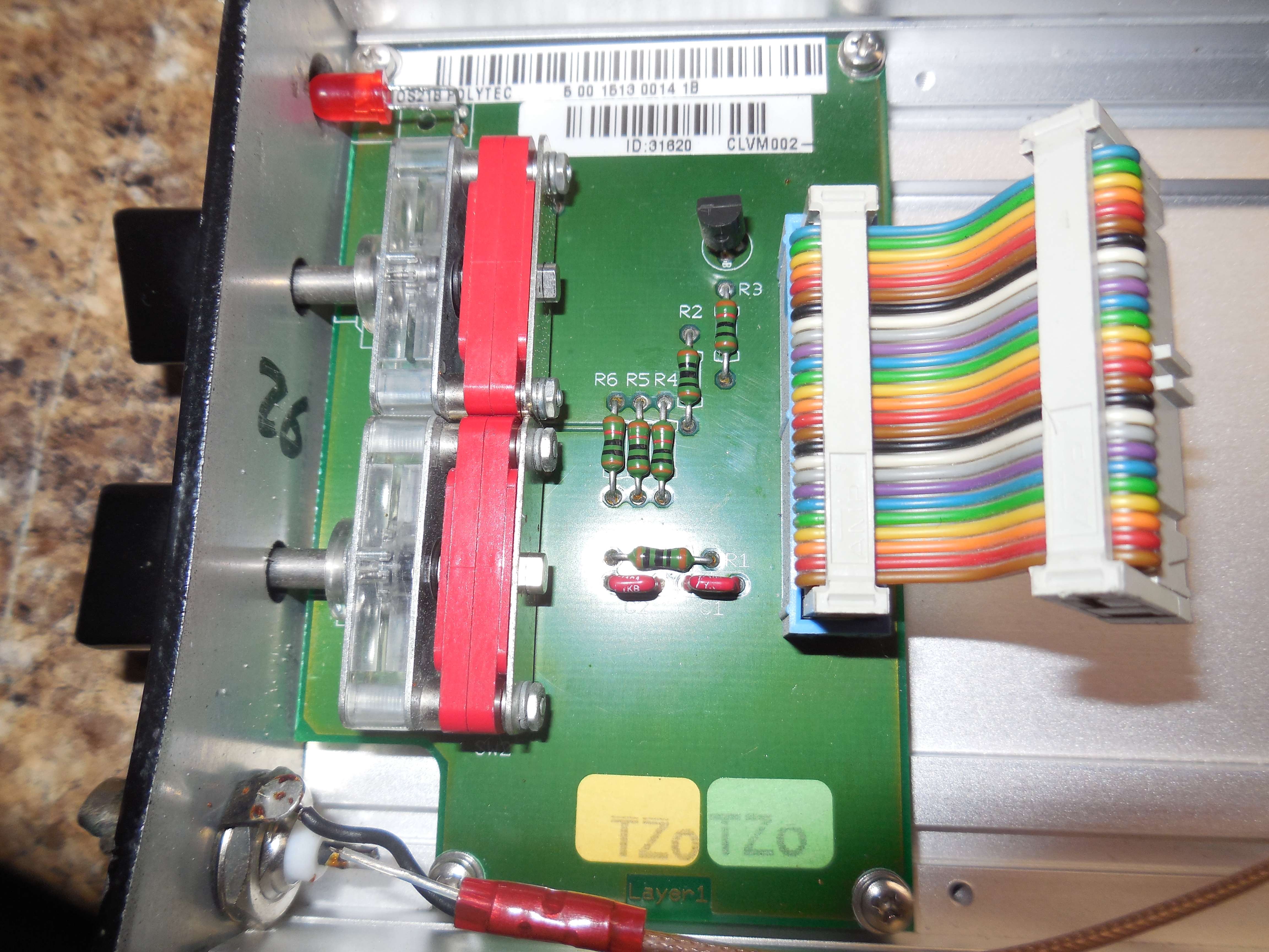
CLV-M200 Input Module (Level Display)
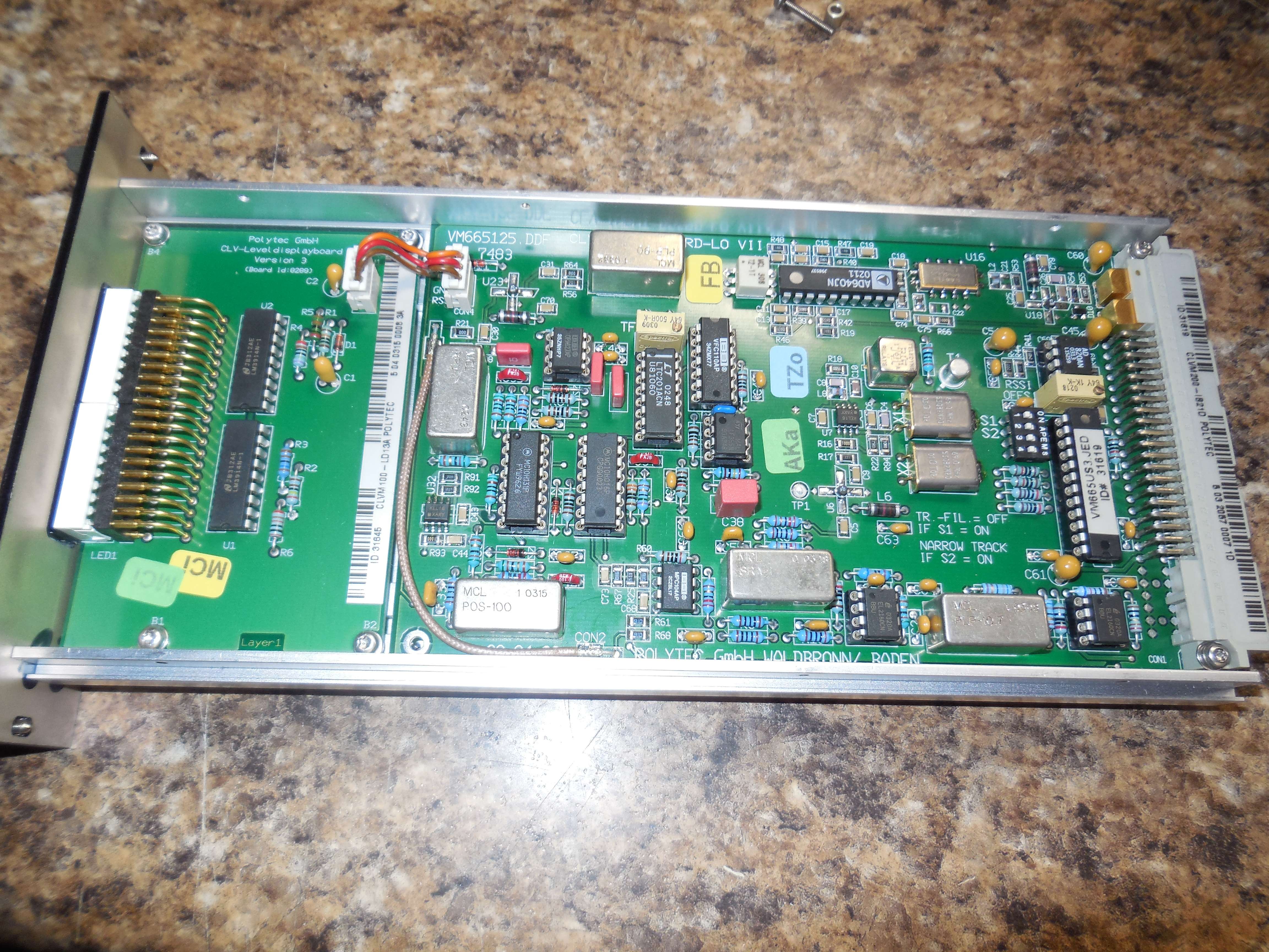
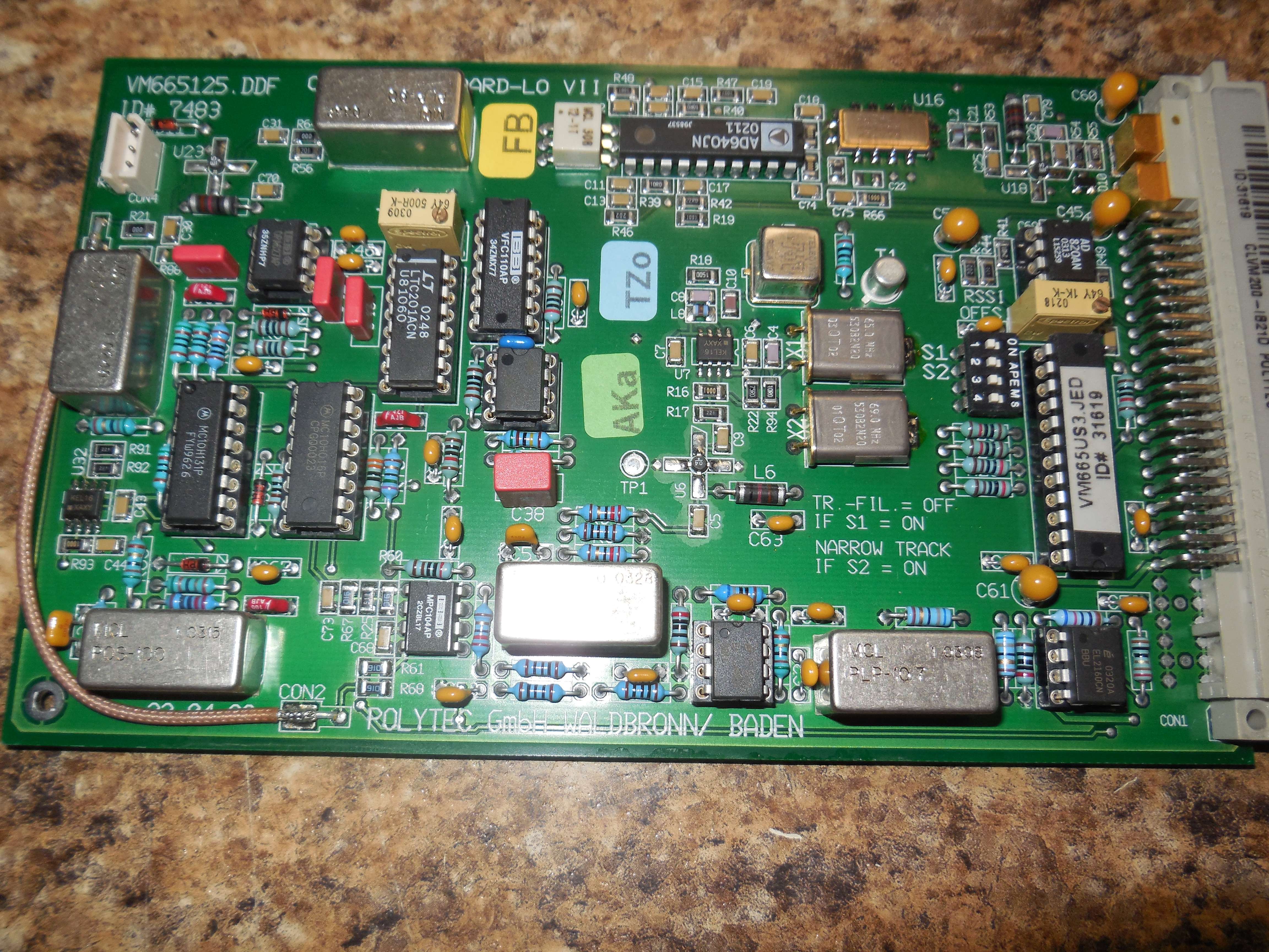
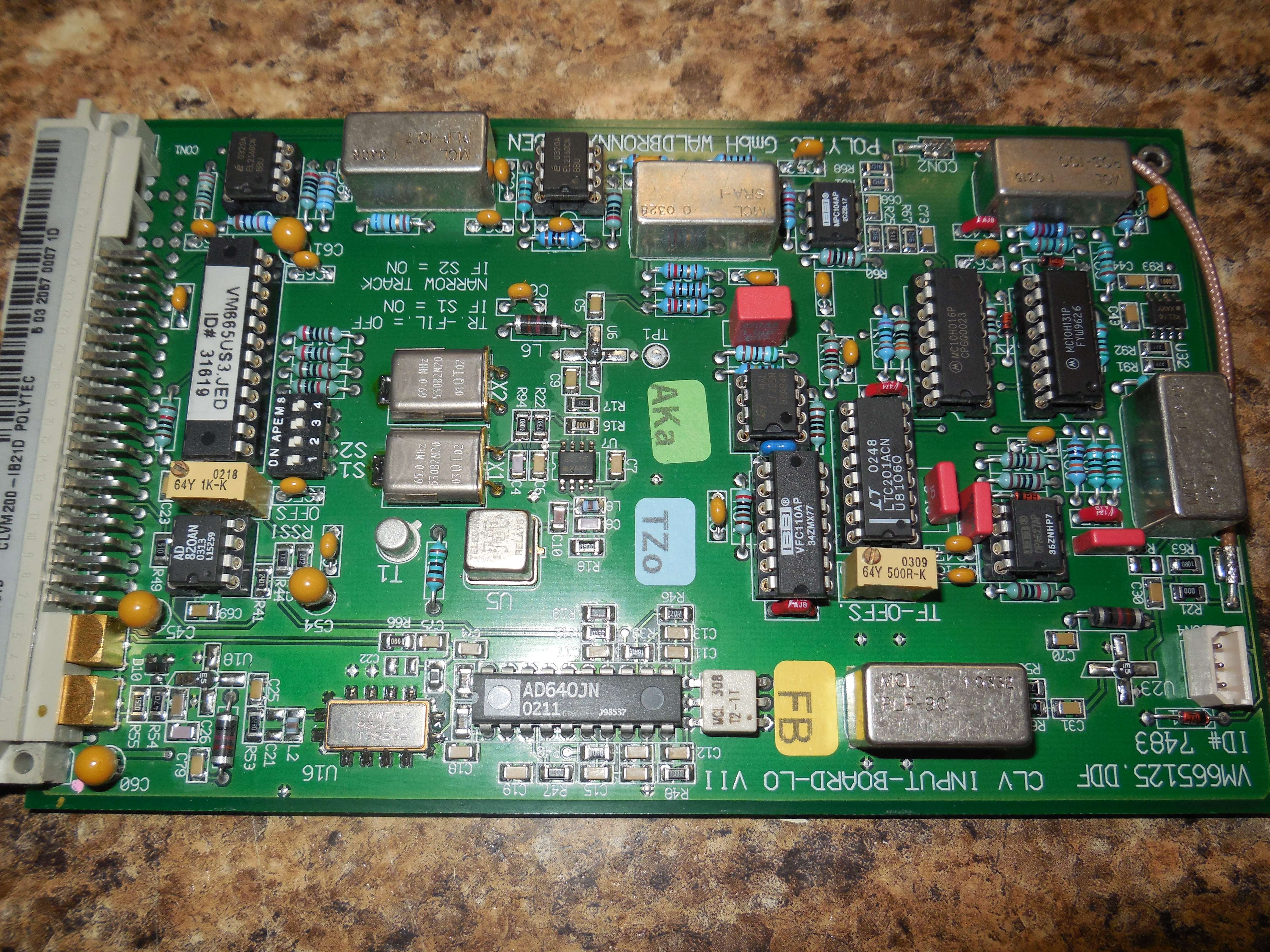
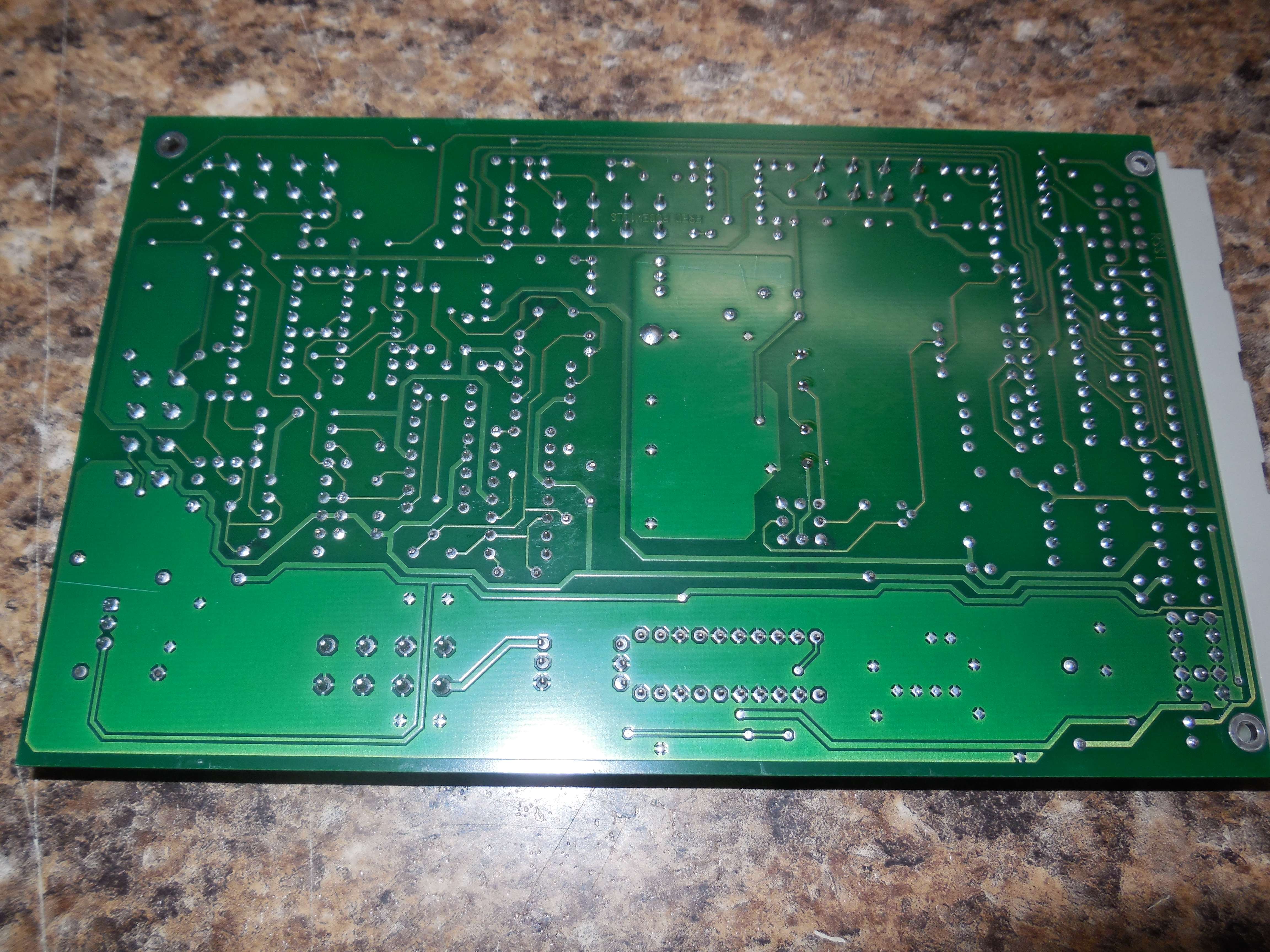
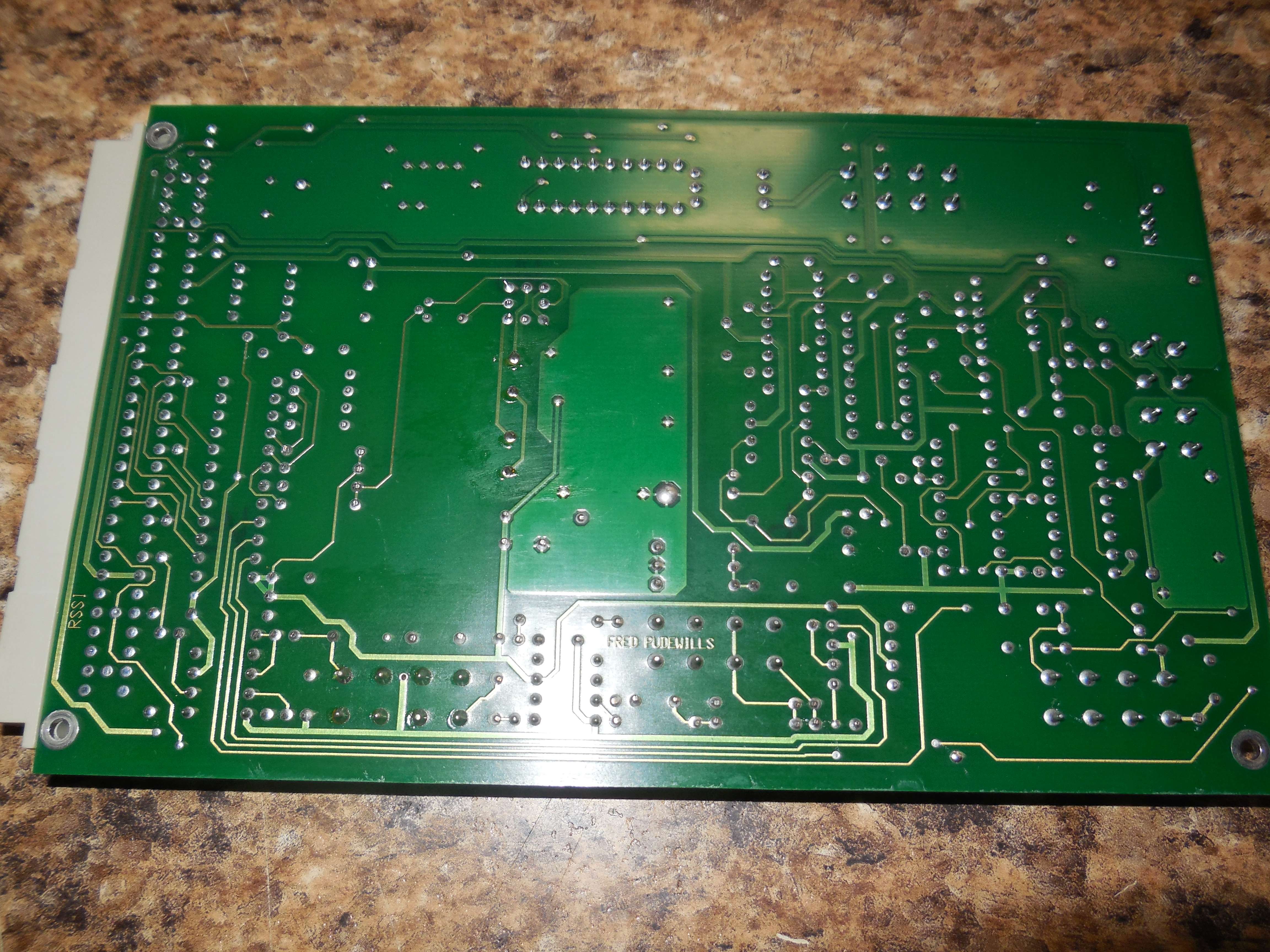
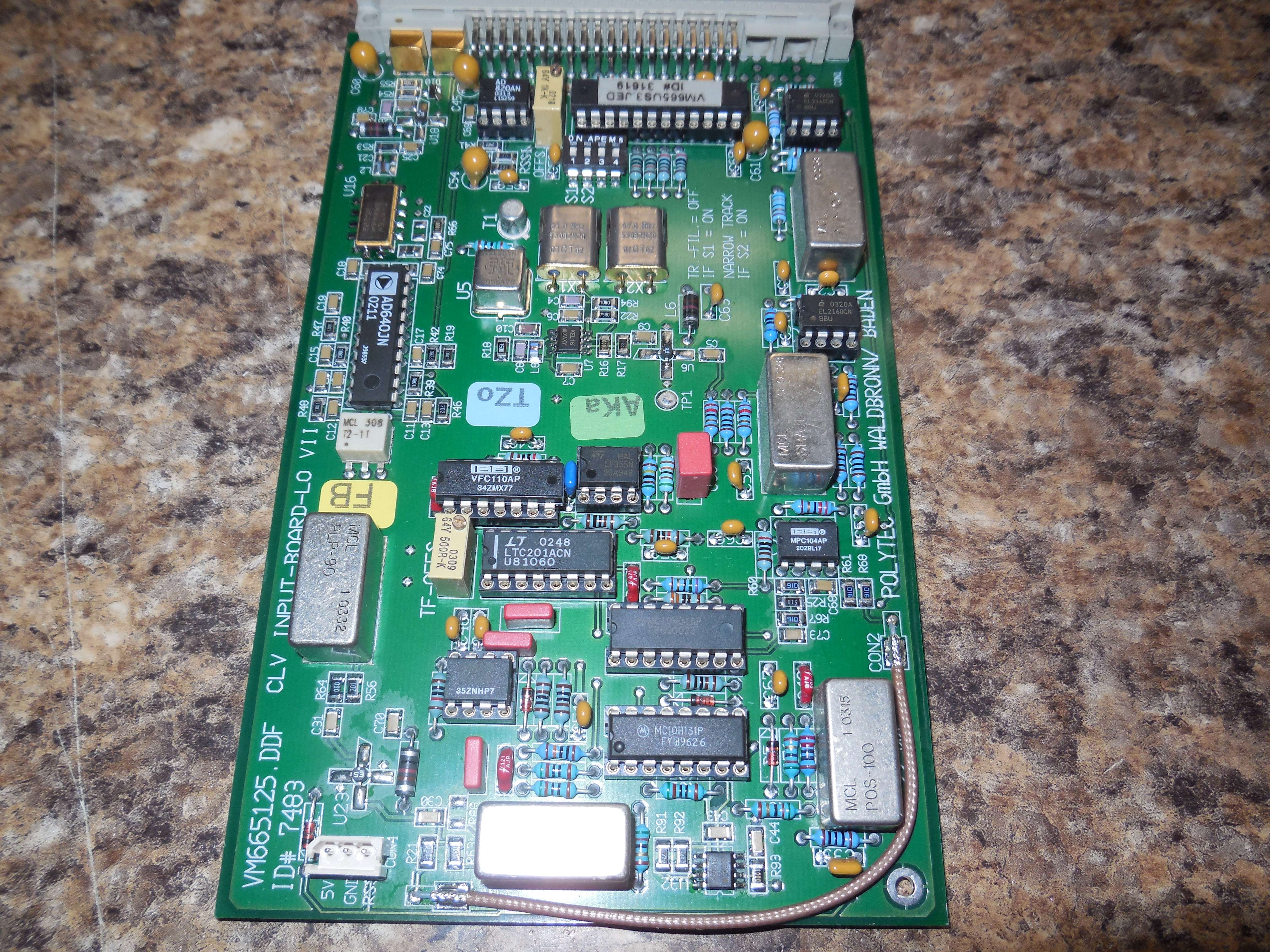
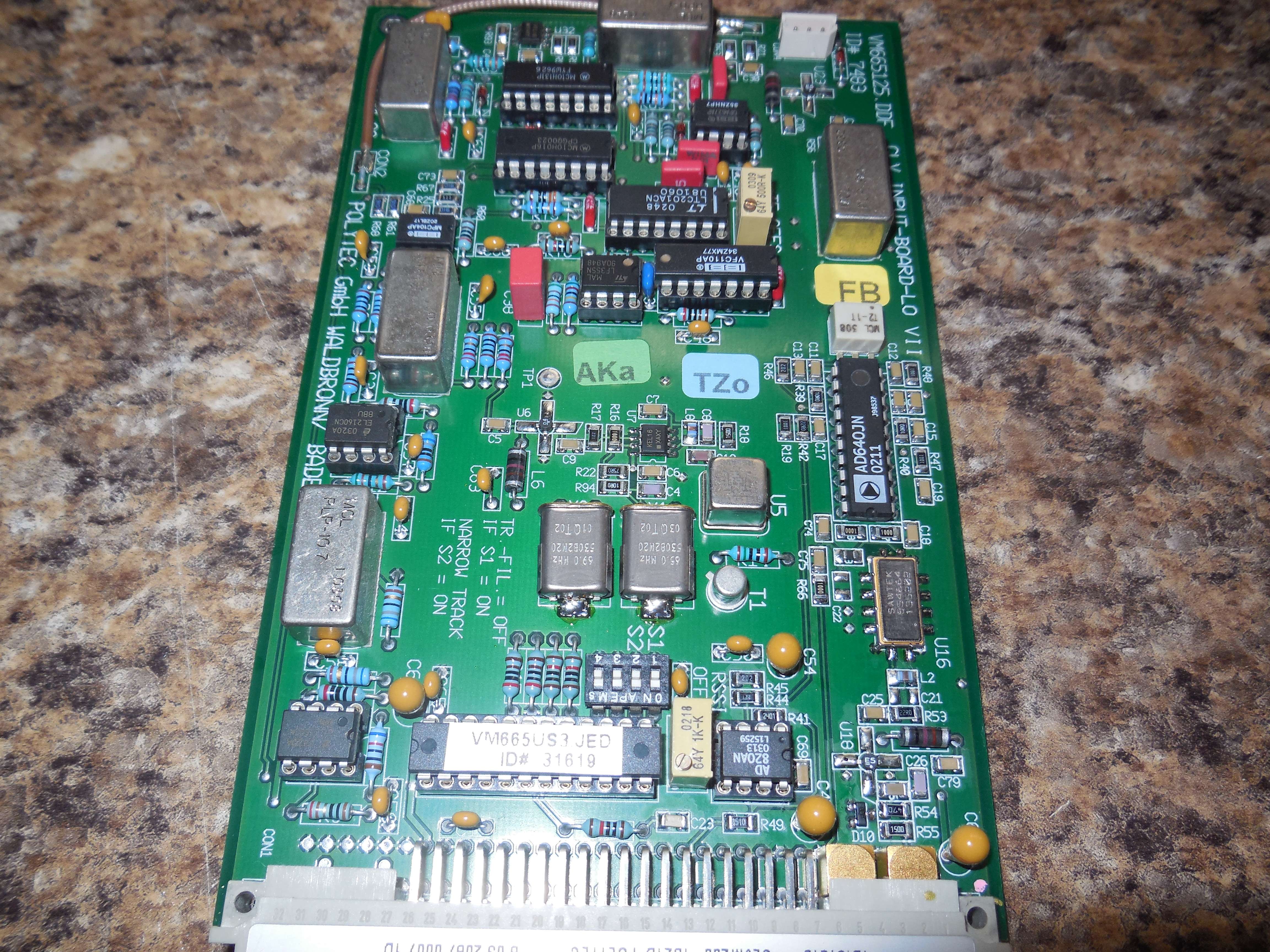
LM3914, AD640, LTC201, VFC110, LF355, KEL16, Sawtek 854664 70 MHz BPF, AD820, MCL PLP-90, MCL RPD-1, MCL POS-100, MCL SRA-1, MCL PLP-10.7, MCL T2-1T, MPC104, OPA627, EL2160.
The two crystals are 69.0 MHz and 65.0 MHz. The Teledyne relay selects either one. It looks like a MC10EL16 is used to create an oscillator with the crystal, its output is them amplified (MAR-4) and fed to the LO port on the SRA-1 mixer.
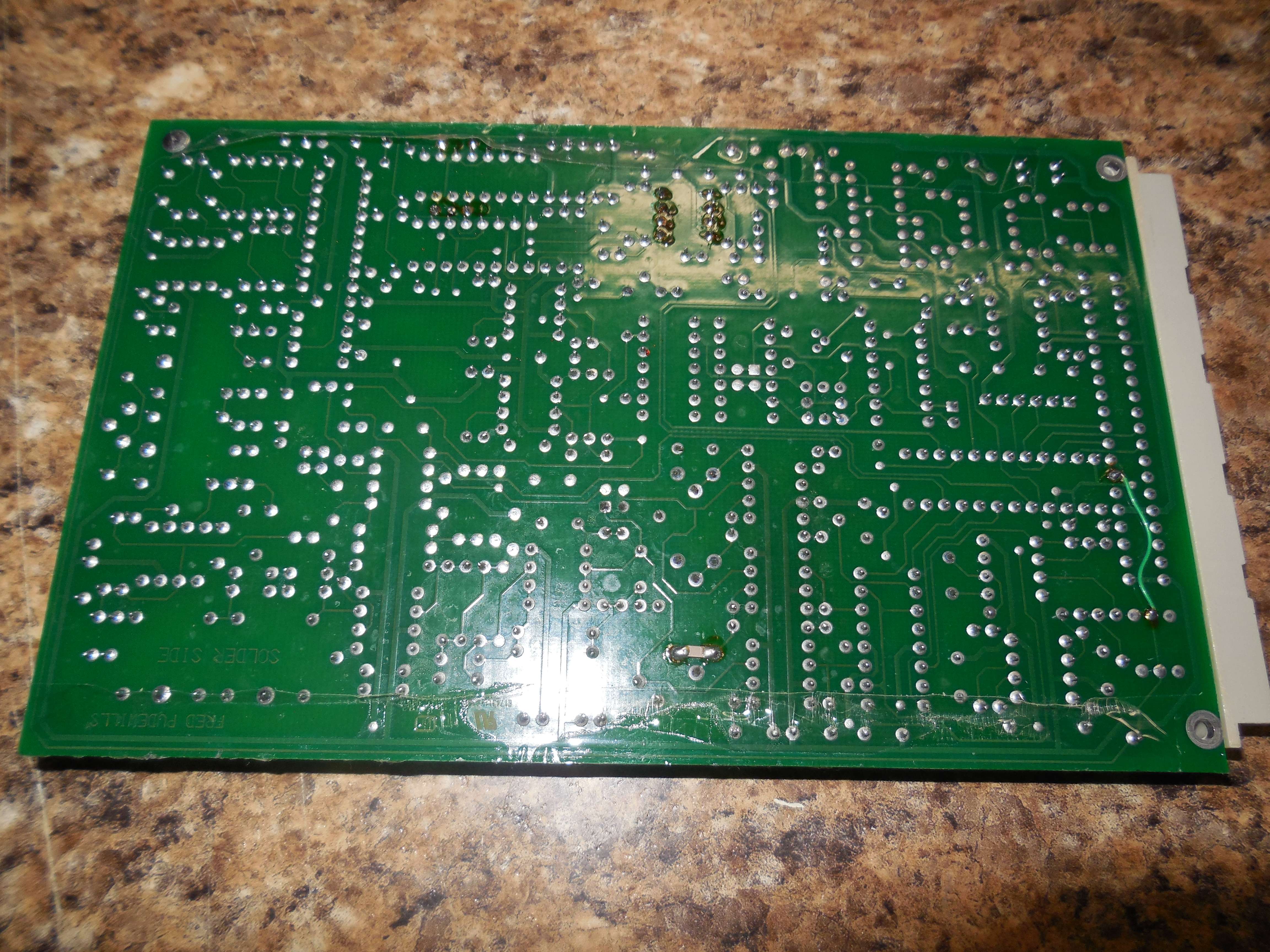
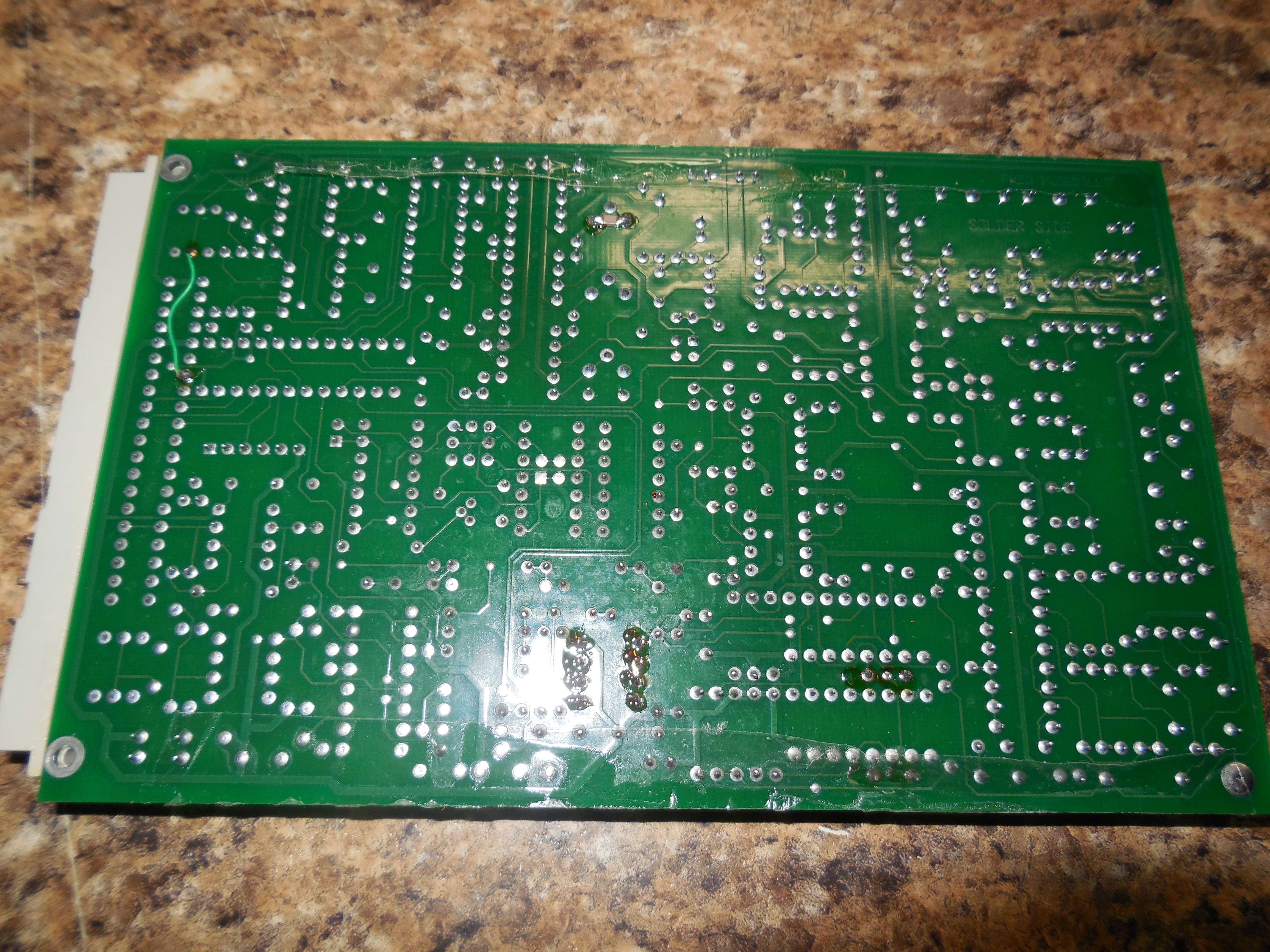
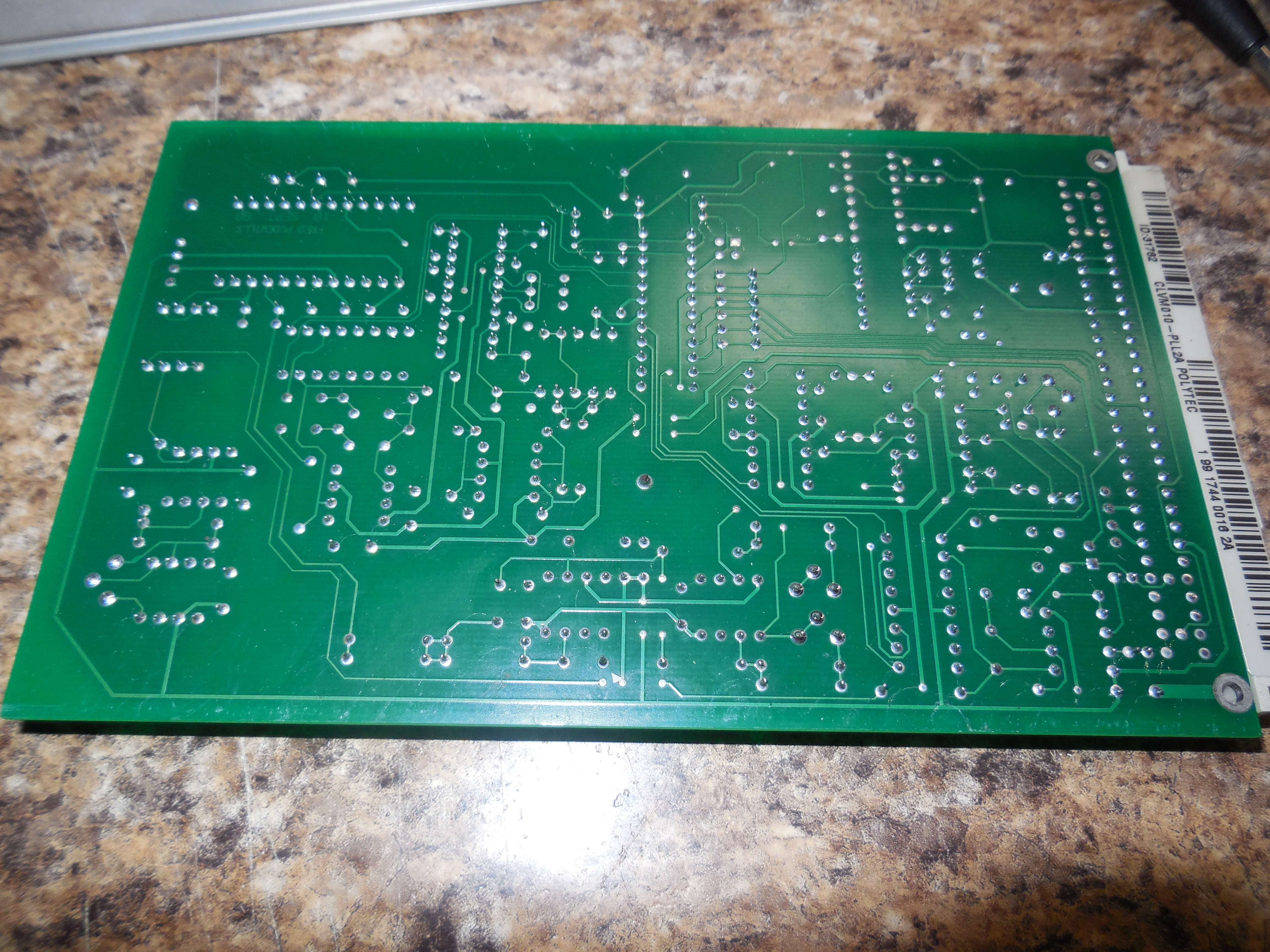
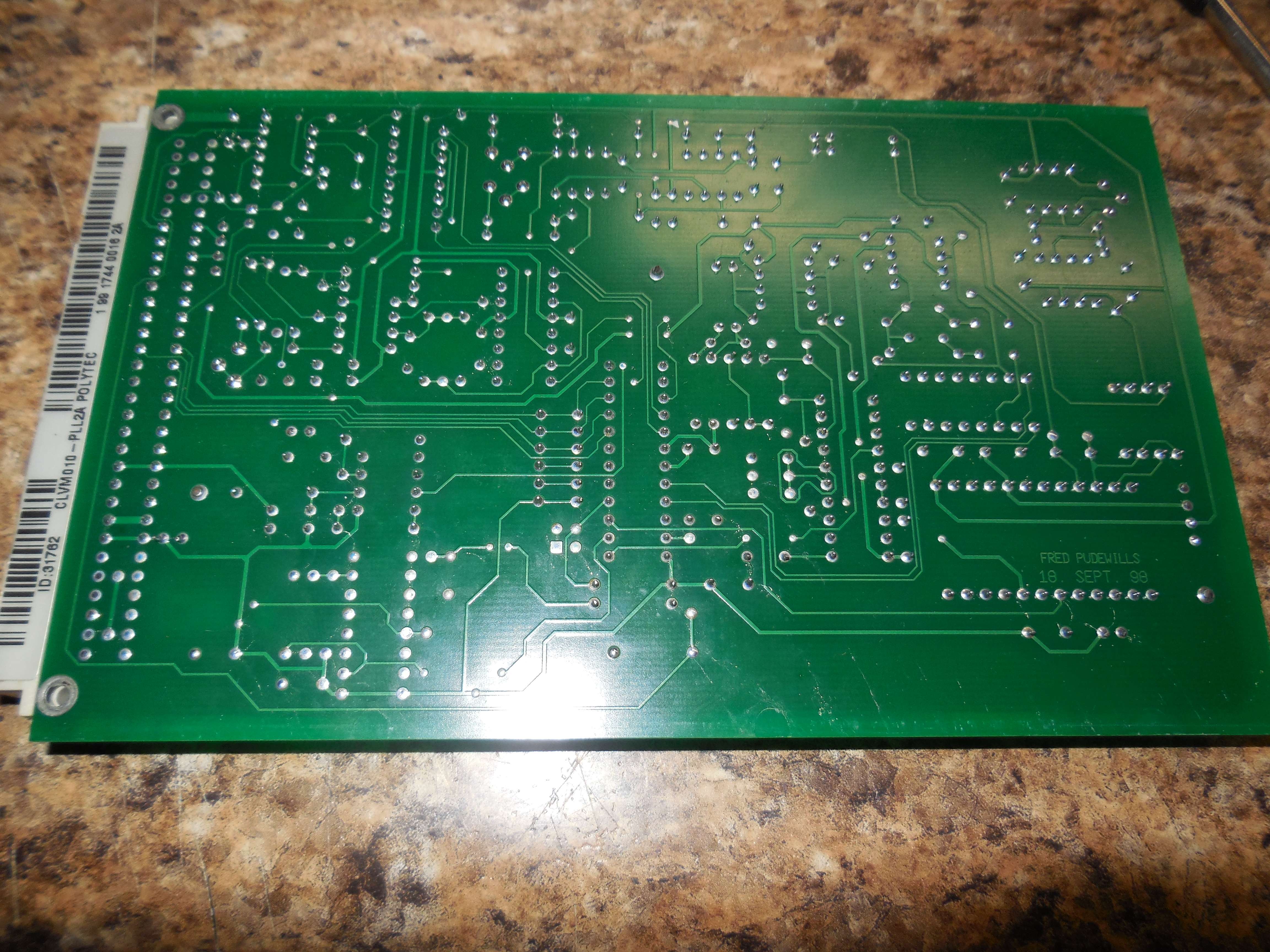
Has the name "FRED PUDEWILLS" on the PC board.
CLV-M030 HS Velocity Decoder Module
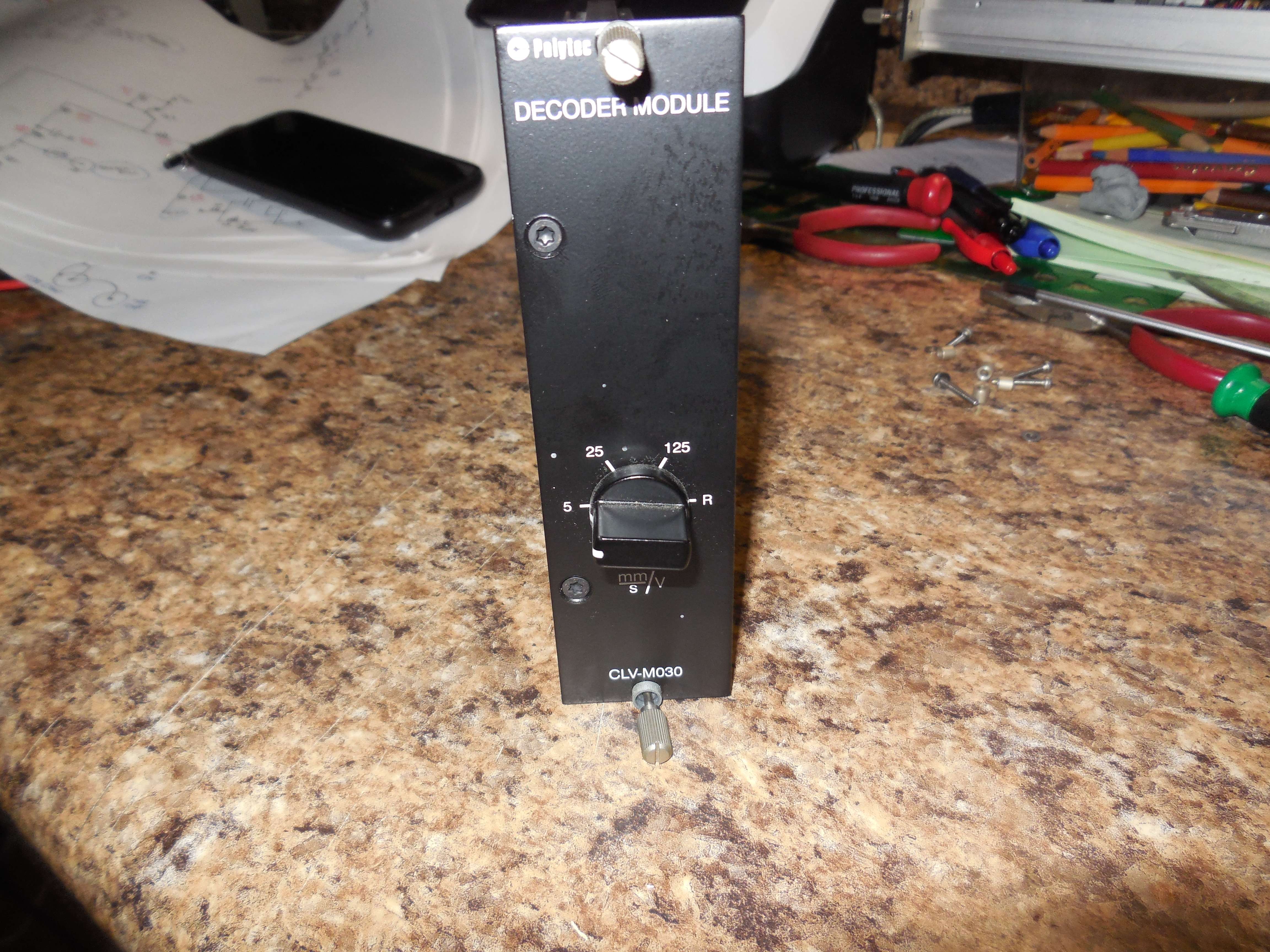
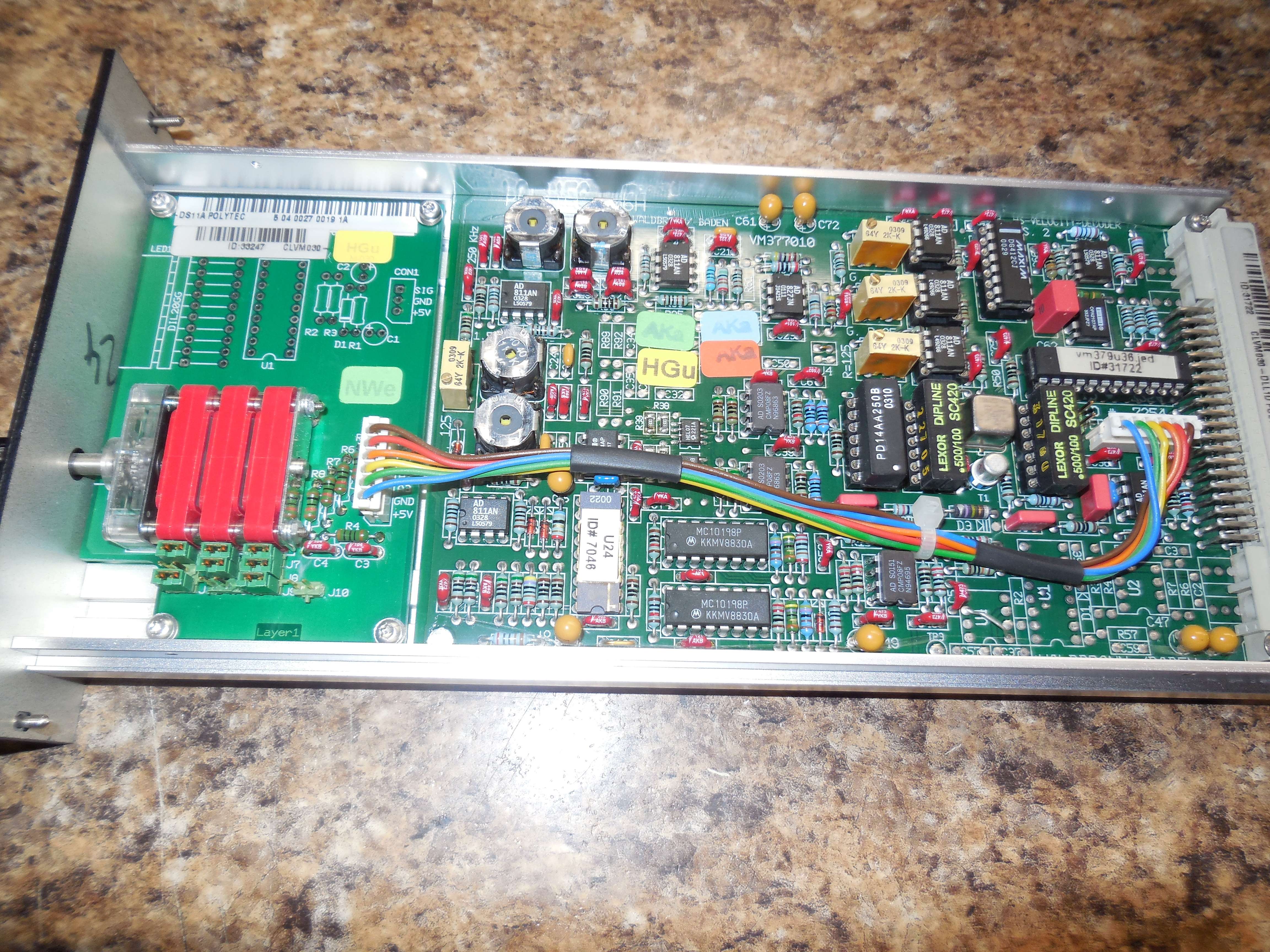
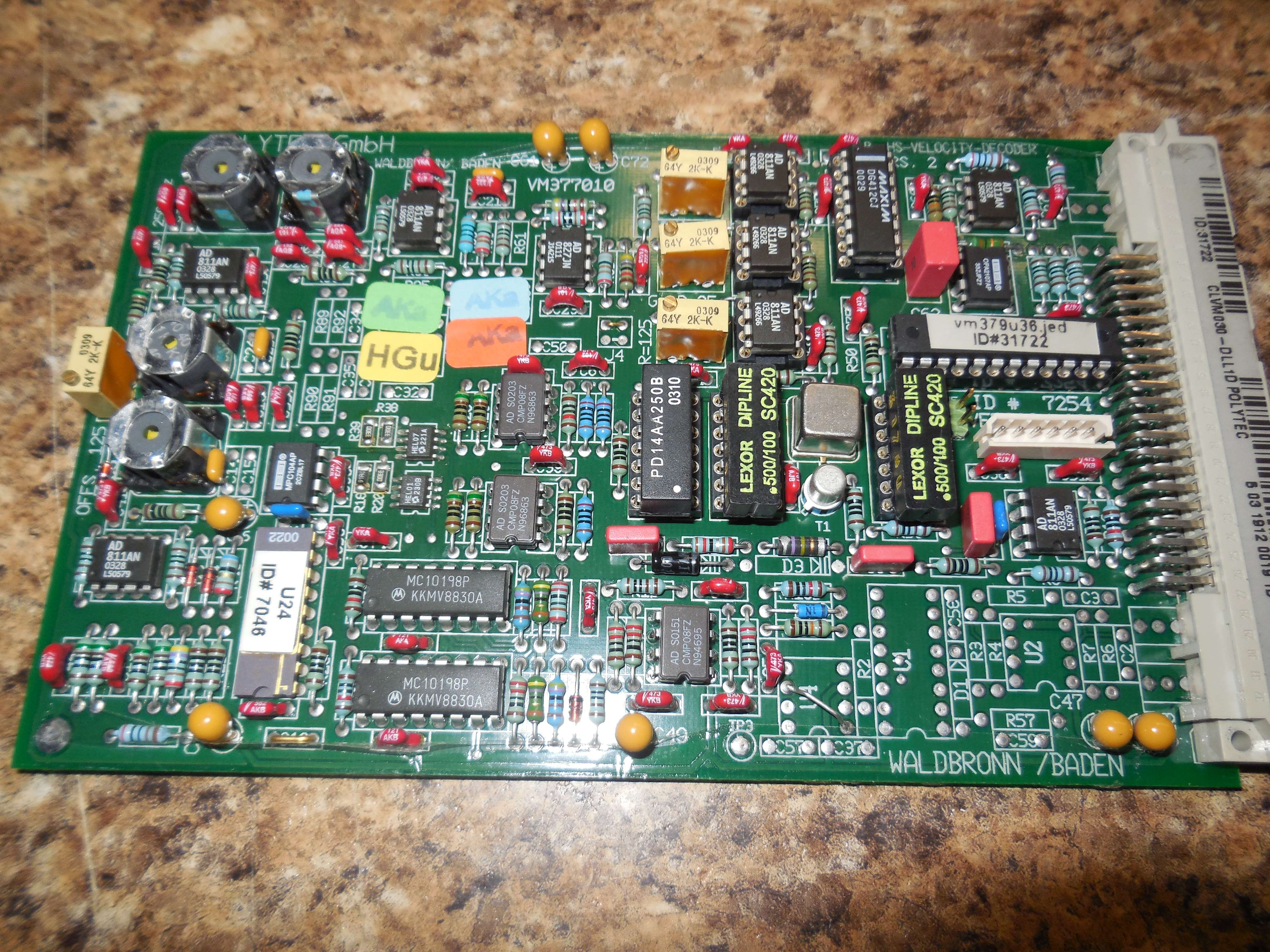
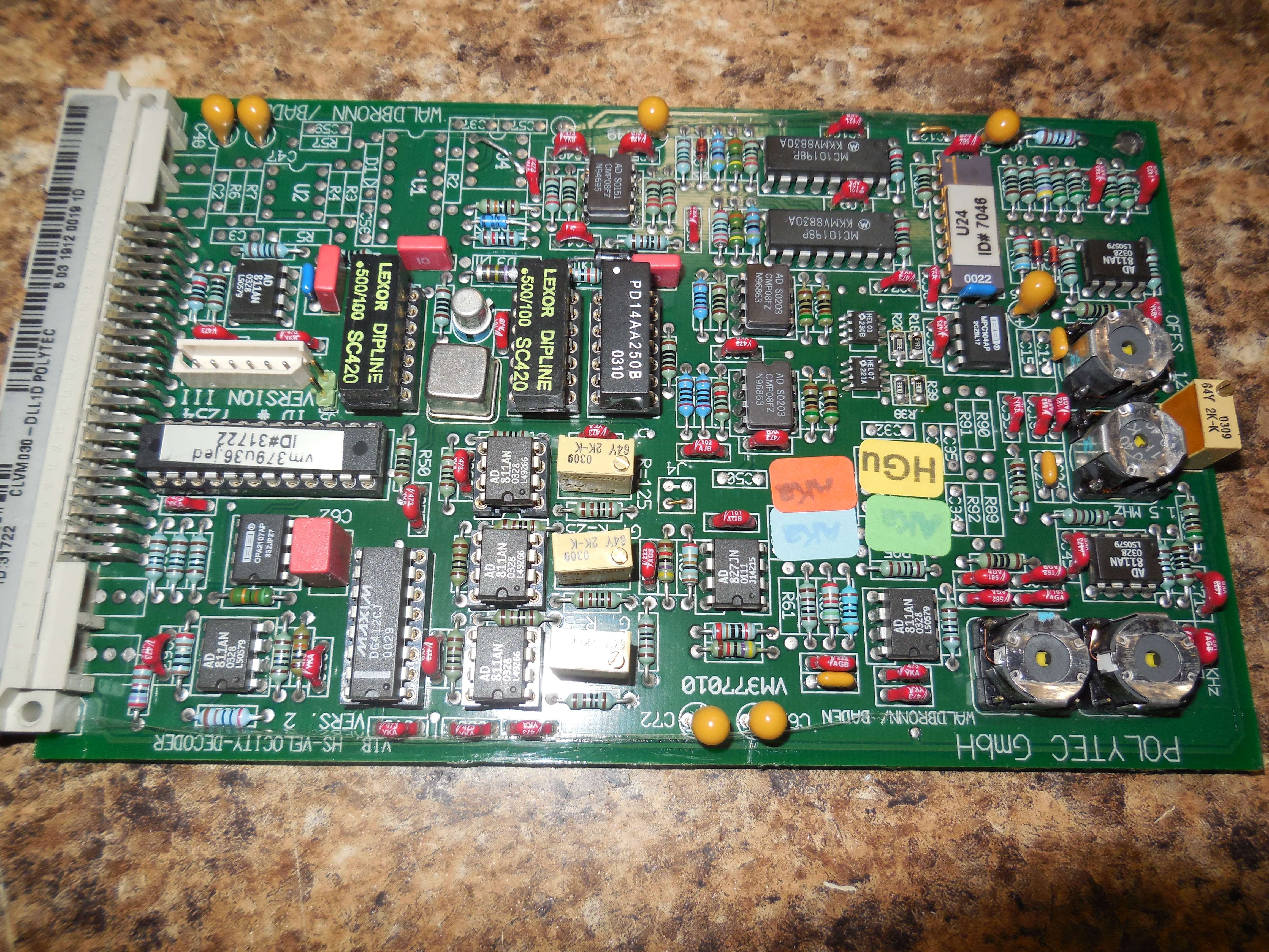
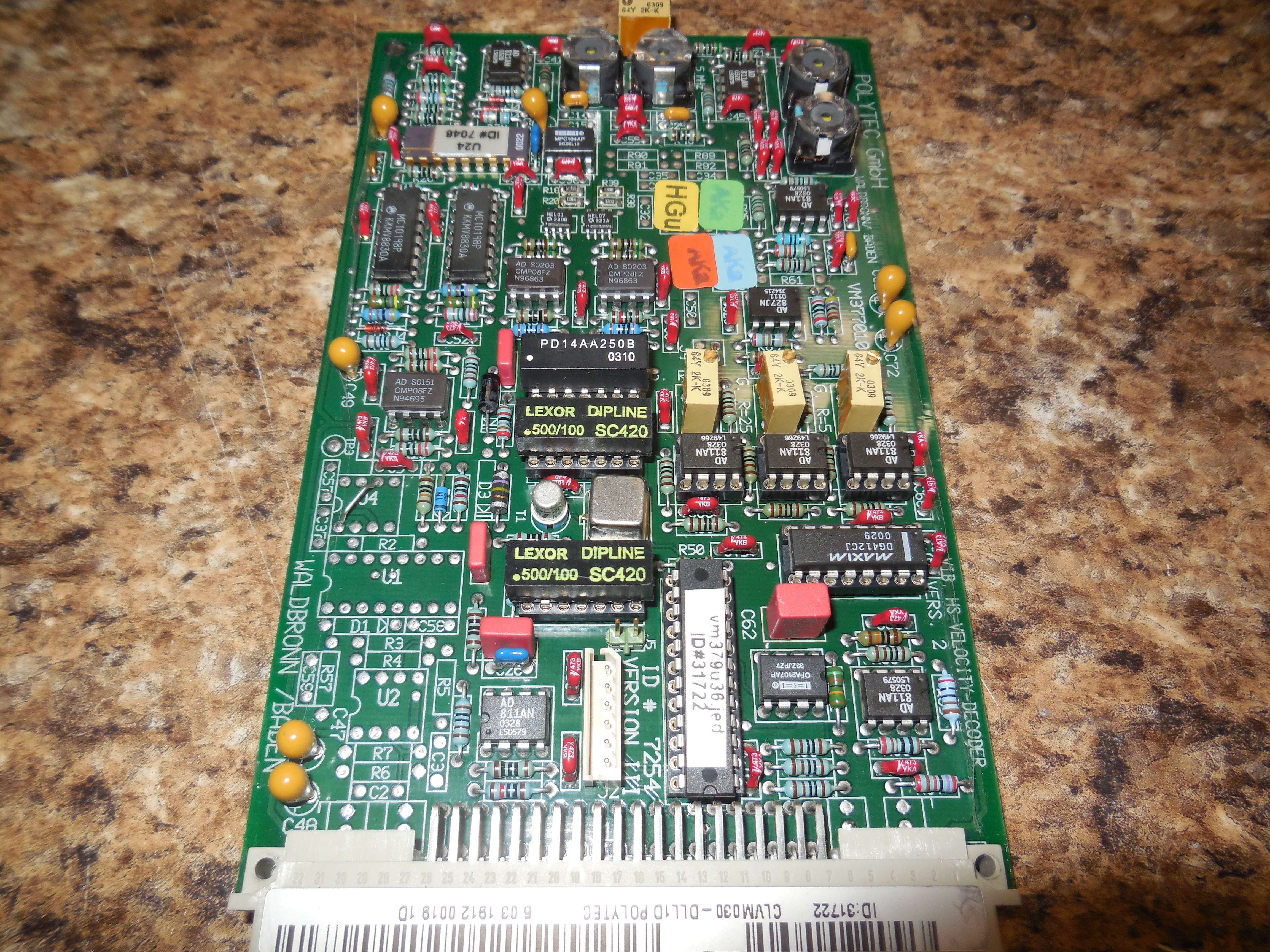
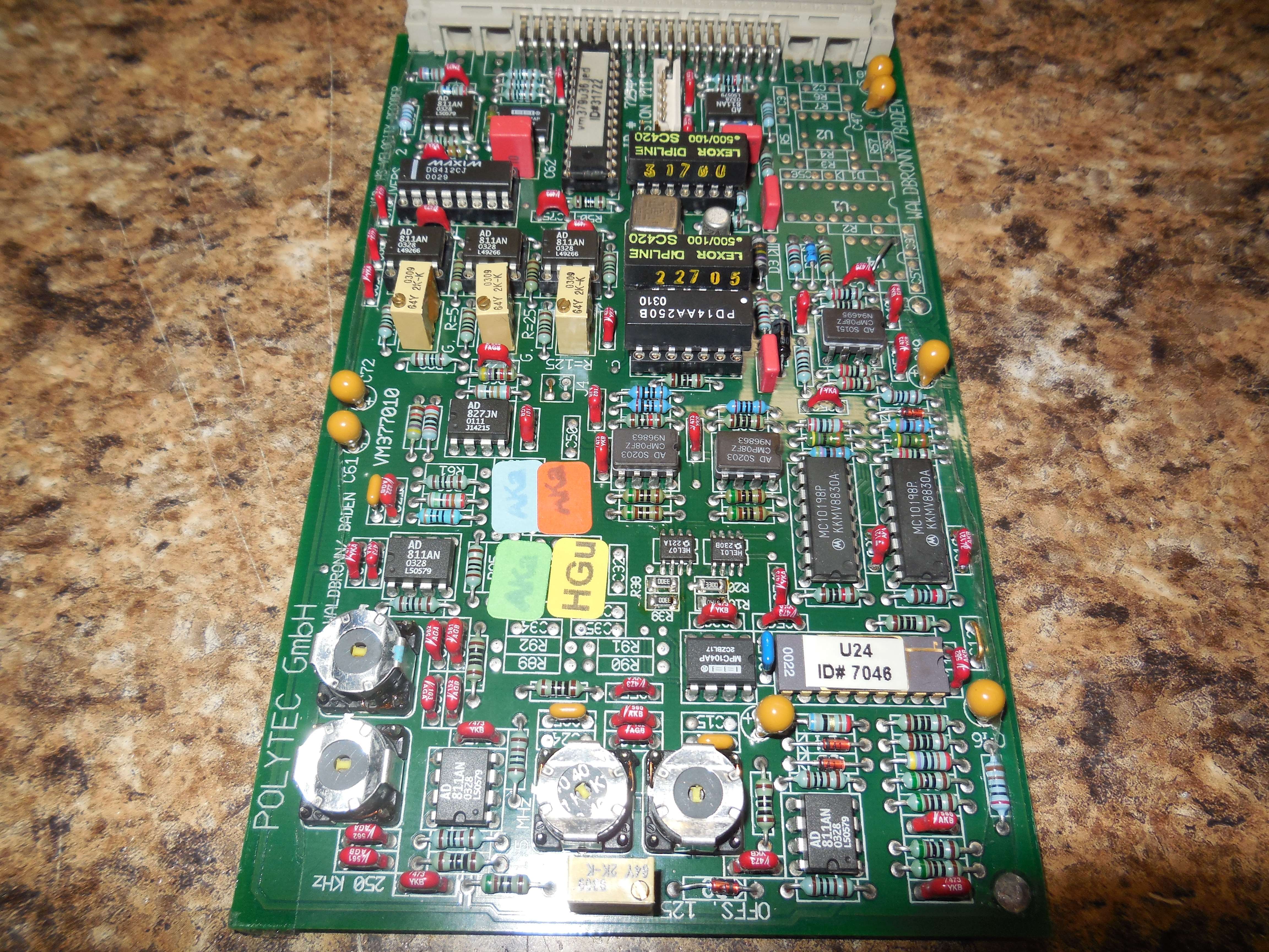
AD811, OPA2107, DG412, CMP08, MC10198, MPC104, HEL01, HEL07, AD827.
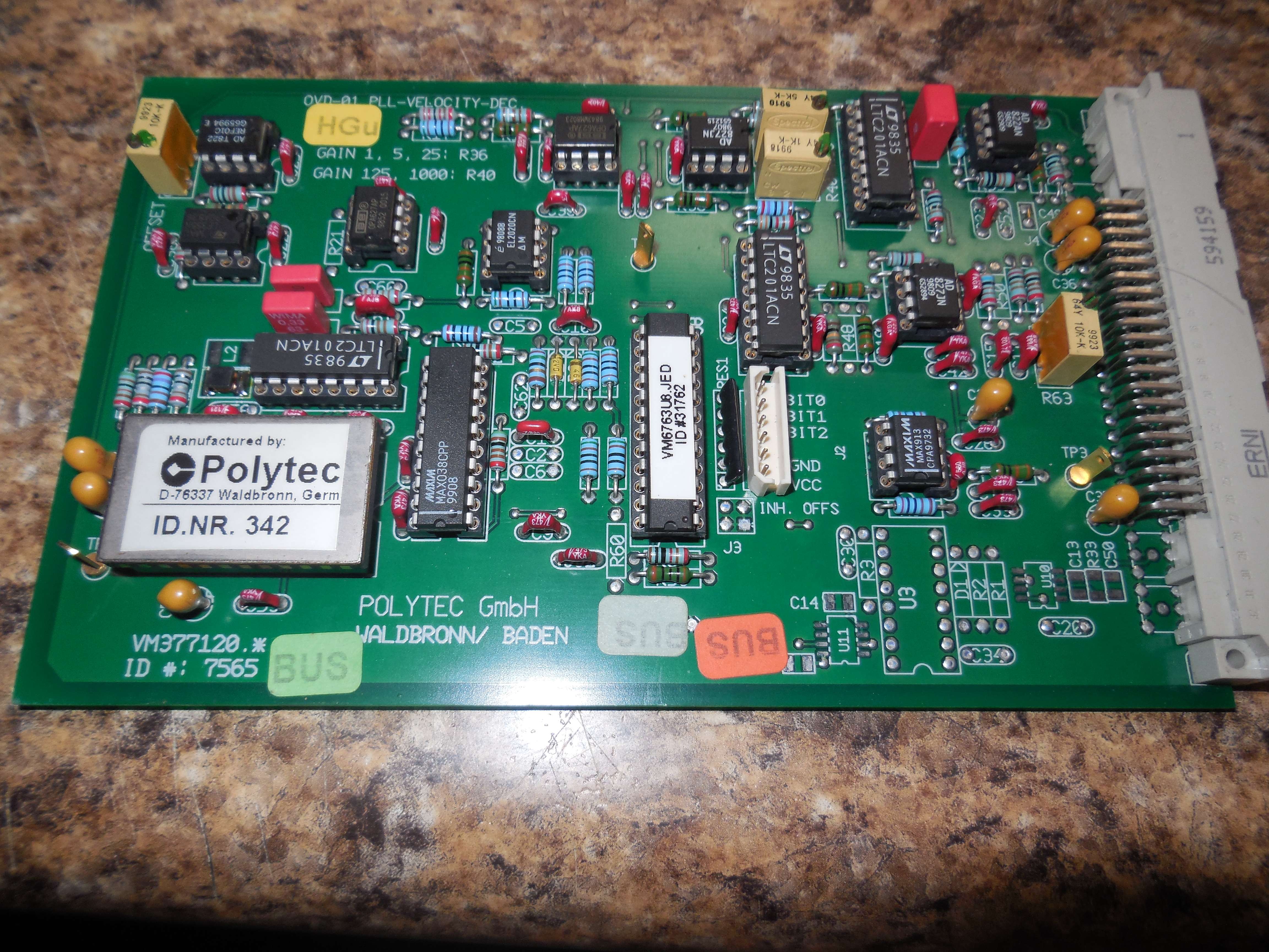
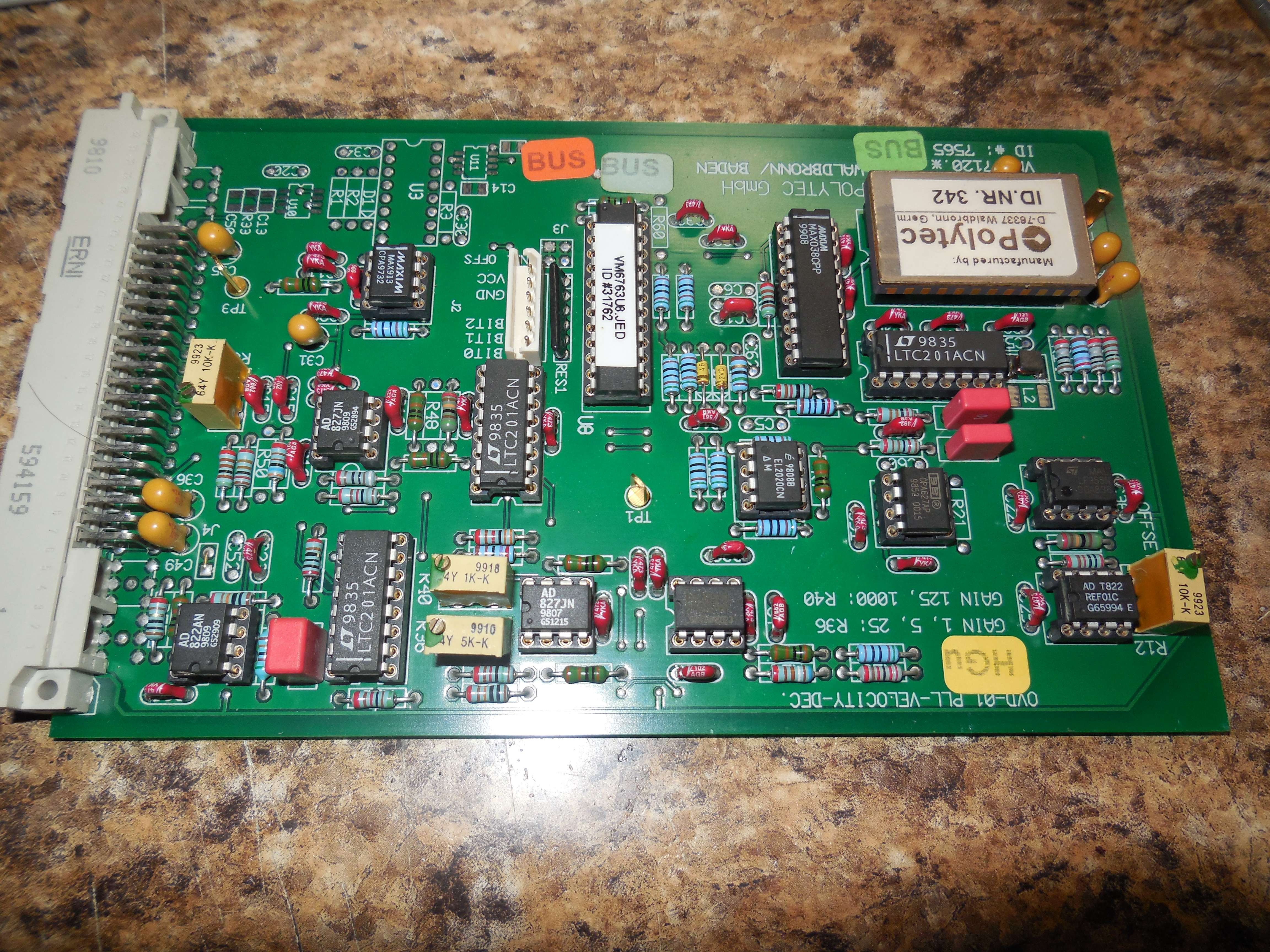
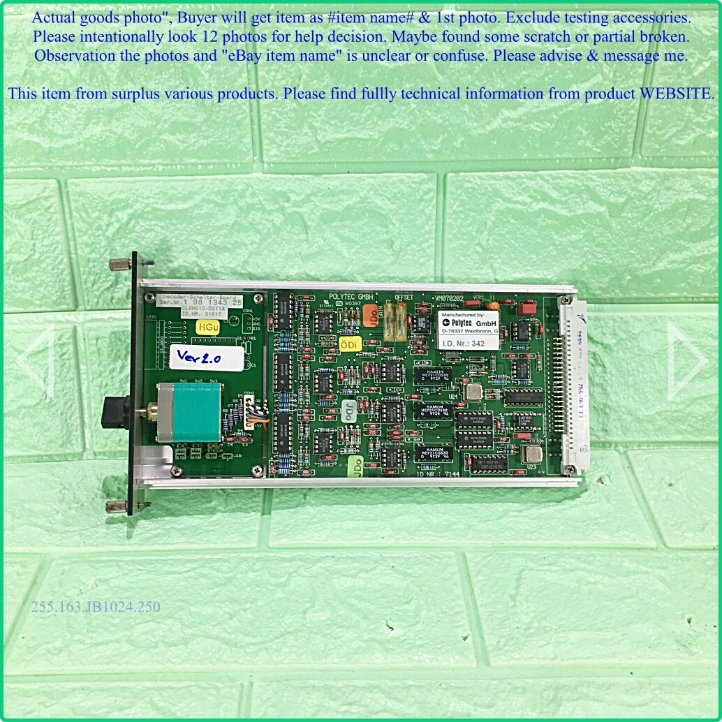
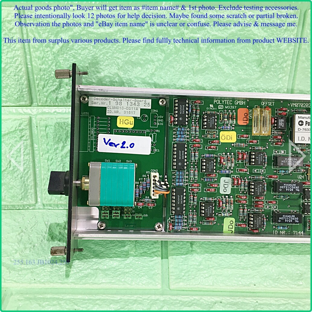
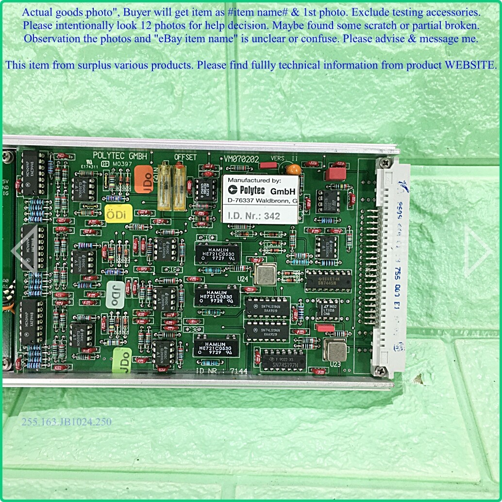
CLV-M010 PLL Velocity Decoder
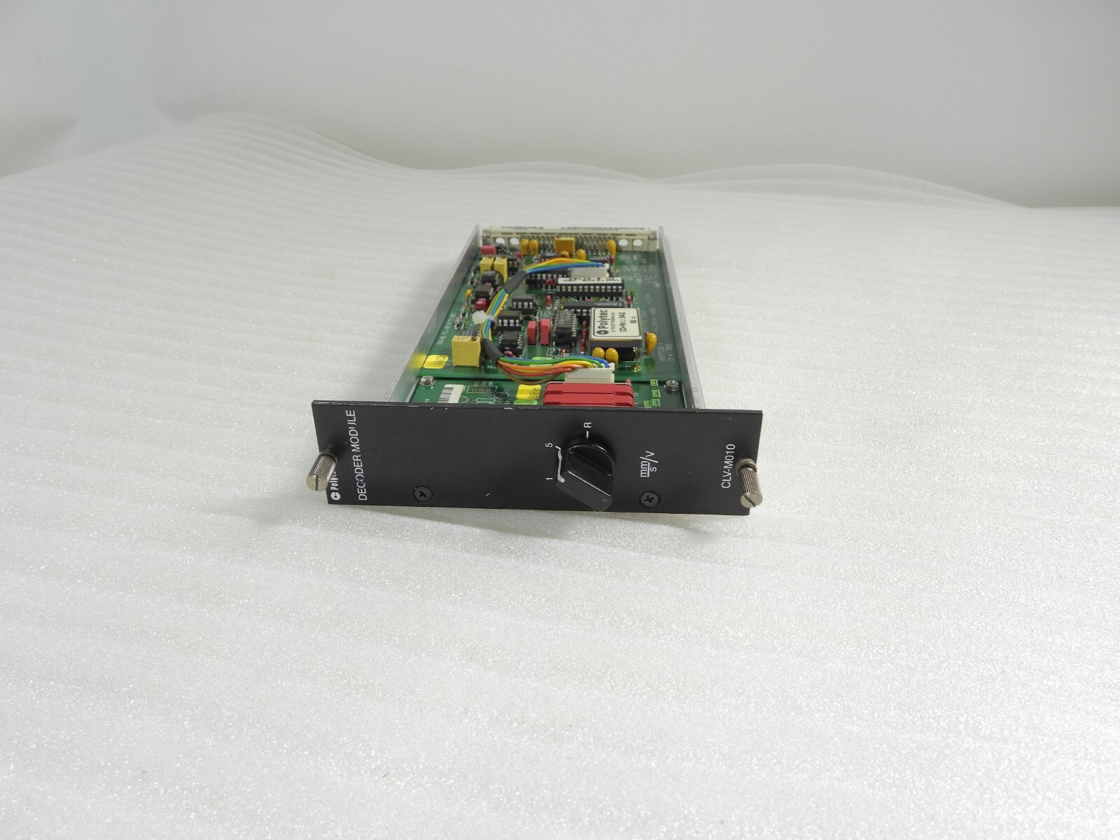
Analog
Velocity Ranges: 1 mm/s/V, 5 mm/s/V
  Max. Velocity: 10 mm/s, 50 mm/s
Frequency Range: 0.5 Hz - 20 kHz, 0.5 Hz - 50 kHz
     Resolution: 0.2 µm/s, 0.5 µm/s
 Recommended Input Module: CLV-M100
Recommended Output Module: CLV-M001, CLV-M003
|
Wire Bundle
 Brown = A0 = BIT0
   Red = A1 = BIT1
Orange = A2 = BIT2
Yellow = A3 = No Connect
 Green = GND = GND
  Blue = +5V = VC
MAX038, LTC201, OPA627, REF01C, EL2020, AD827, AD822, MAX913, LF355.
The large PLL IC (U2) label reads: Manufactured by Polytec D-76337 Waldbronn, Germ ID.NR. 342
Under the label is... nothing. Hand written on the bottom of the IC is: 501549 98
It may be equivalent to the Micro Networks MD3810.
The pictures of the other board were found on eBay. They have a hand written label which says "Ver 2.0" and appear to use a different layout bu the same PLL IC.
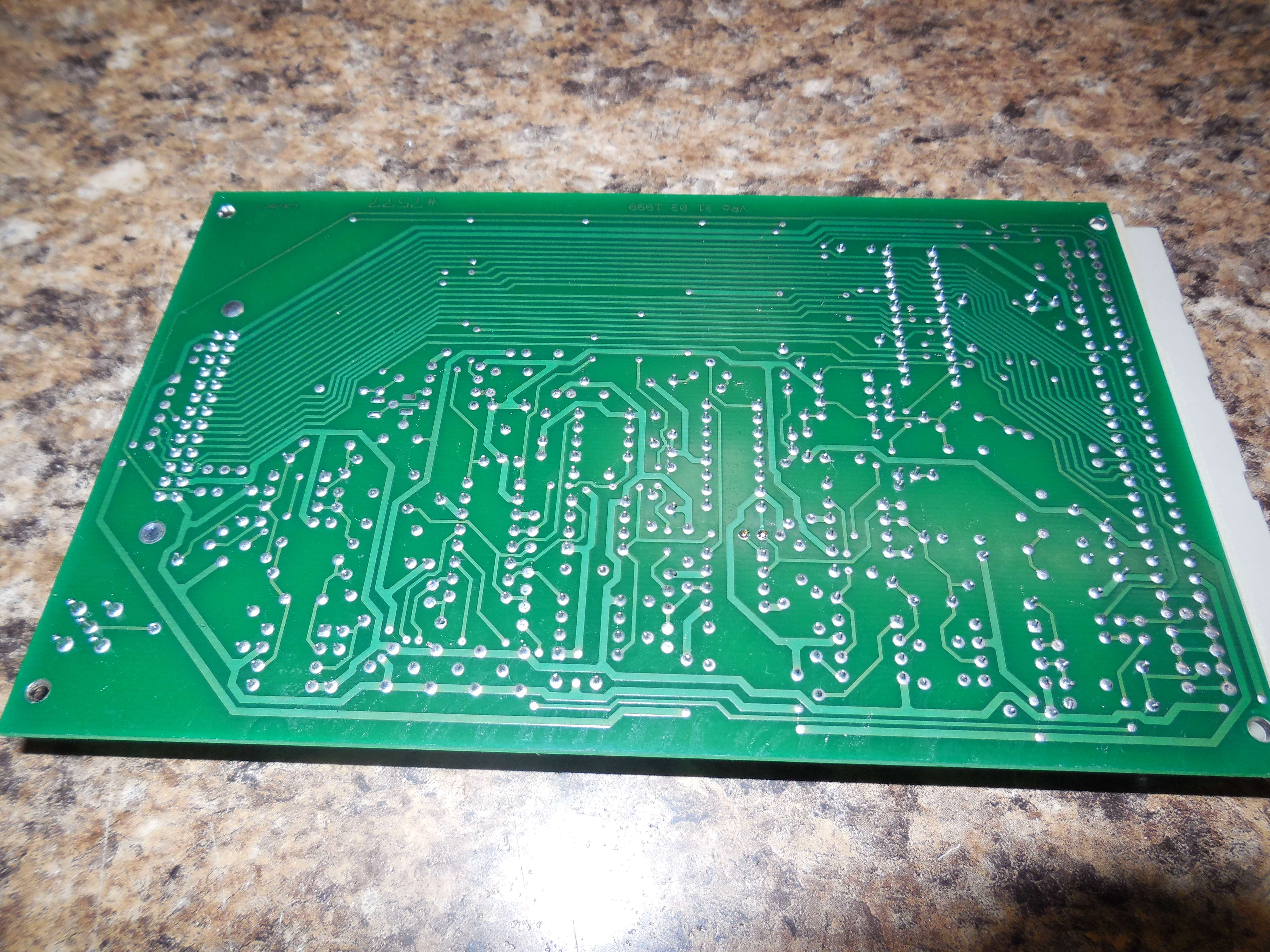
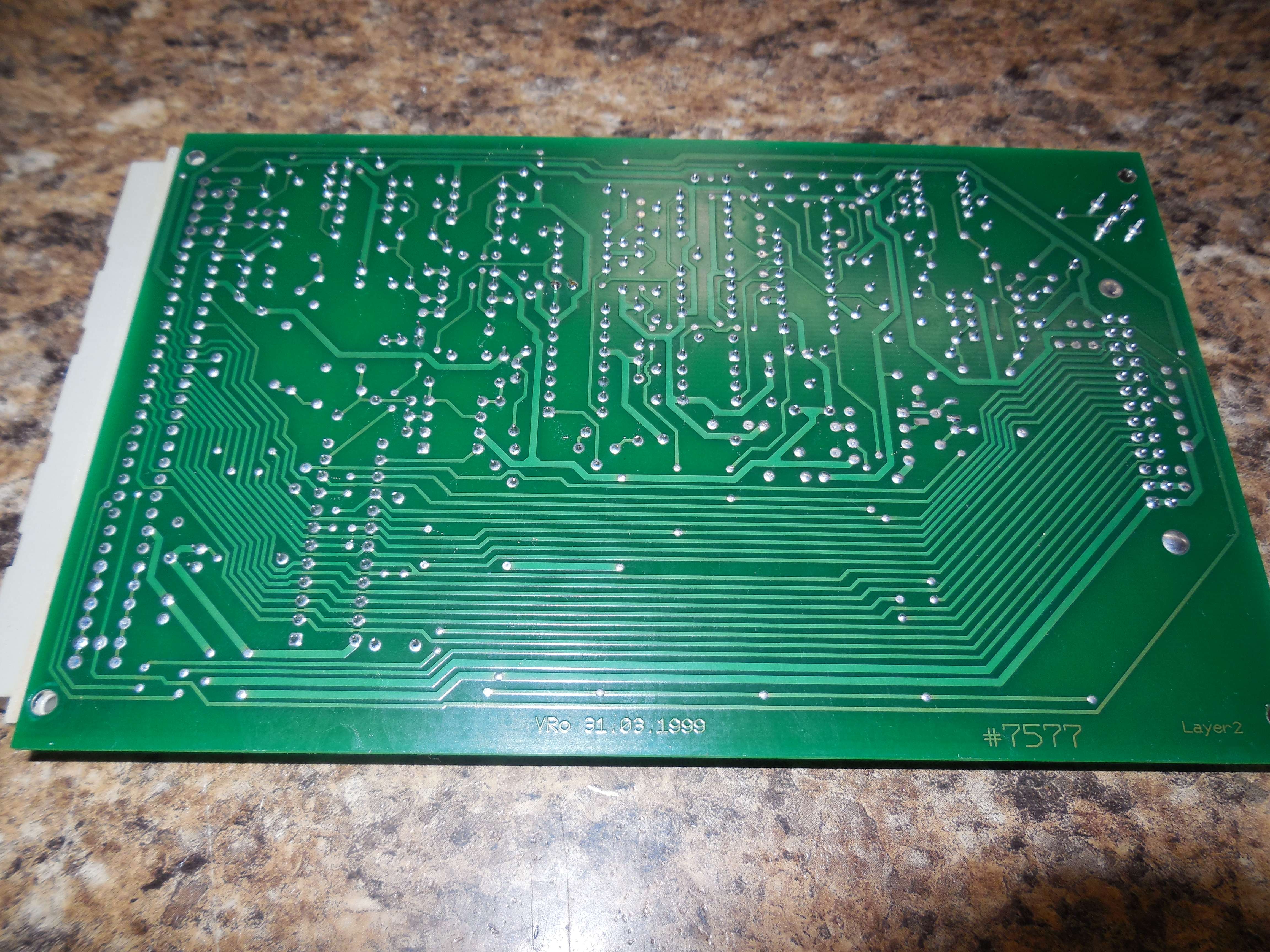
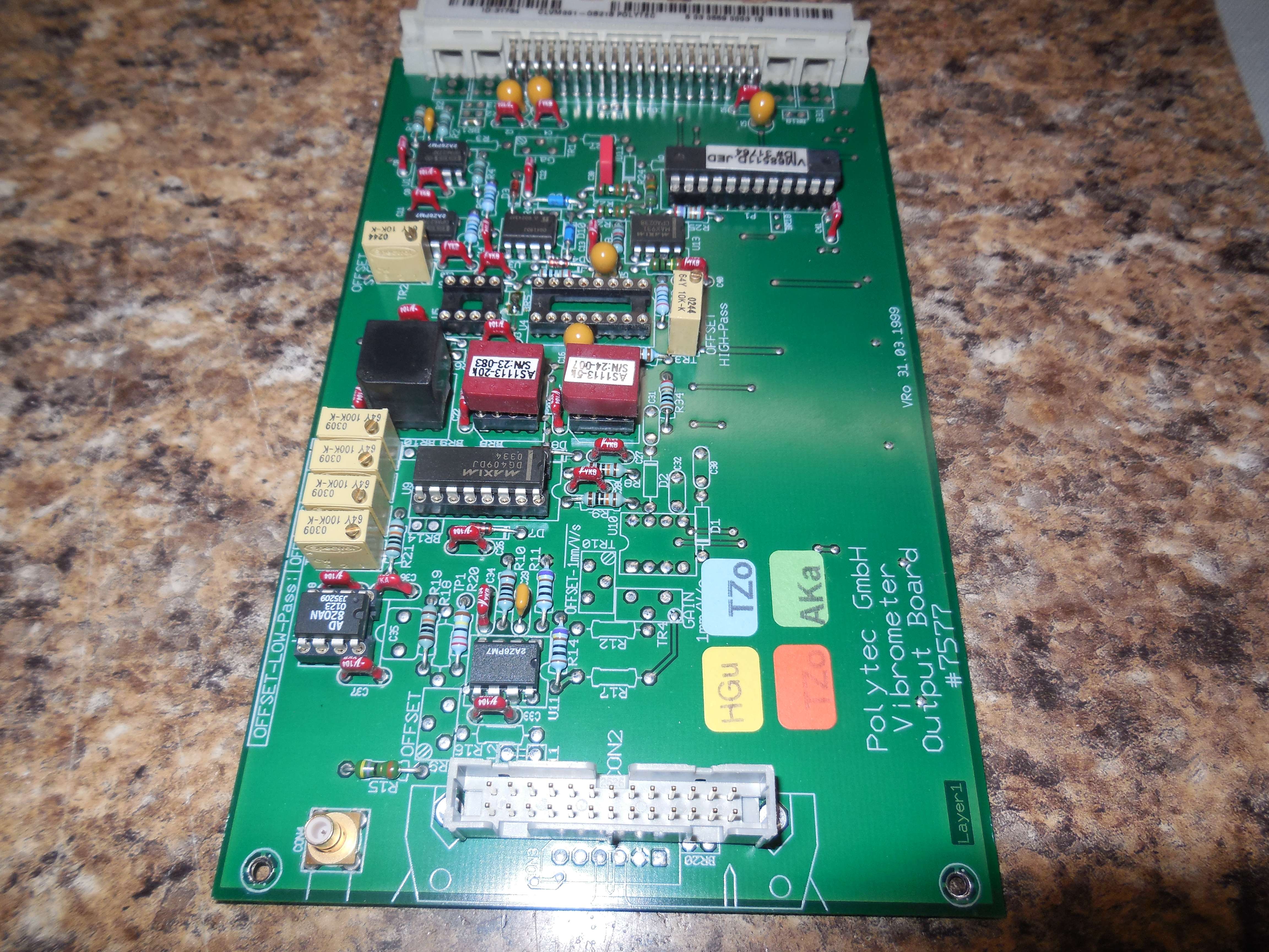
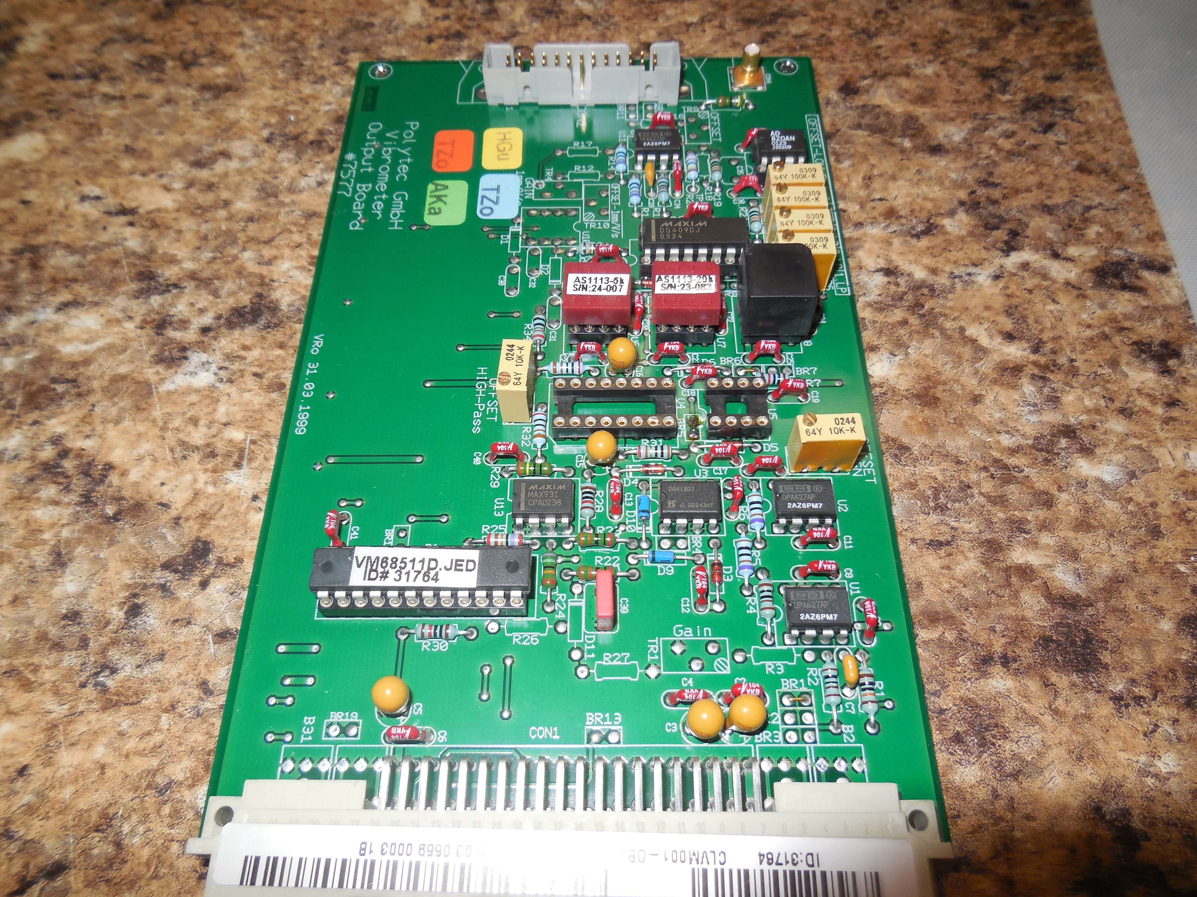
CLV-M003 Output Module
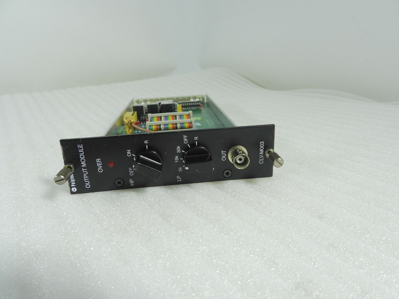
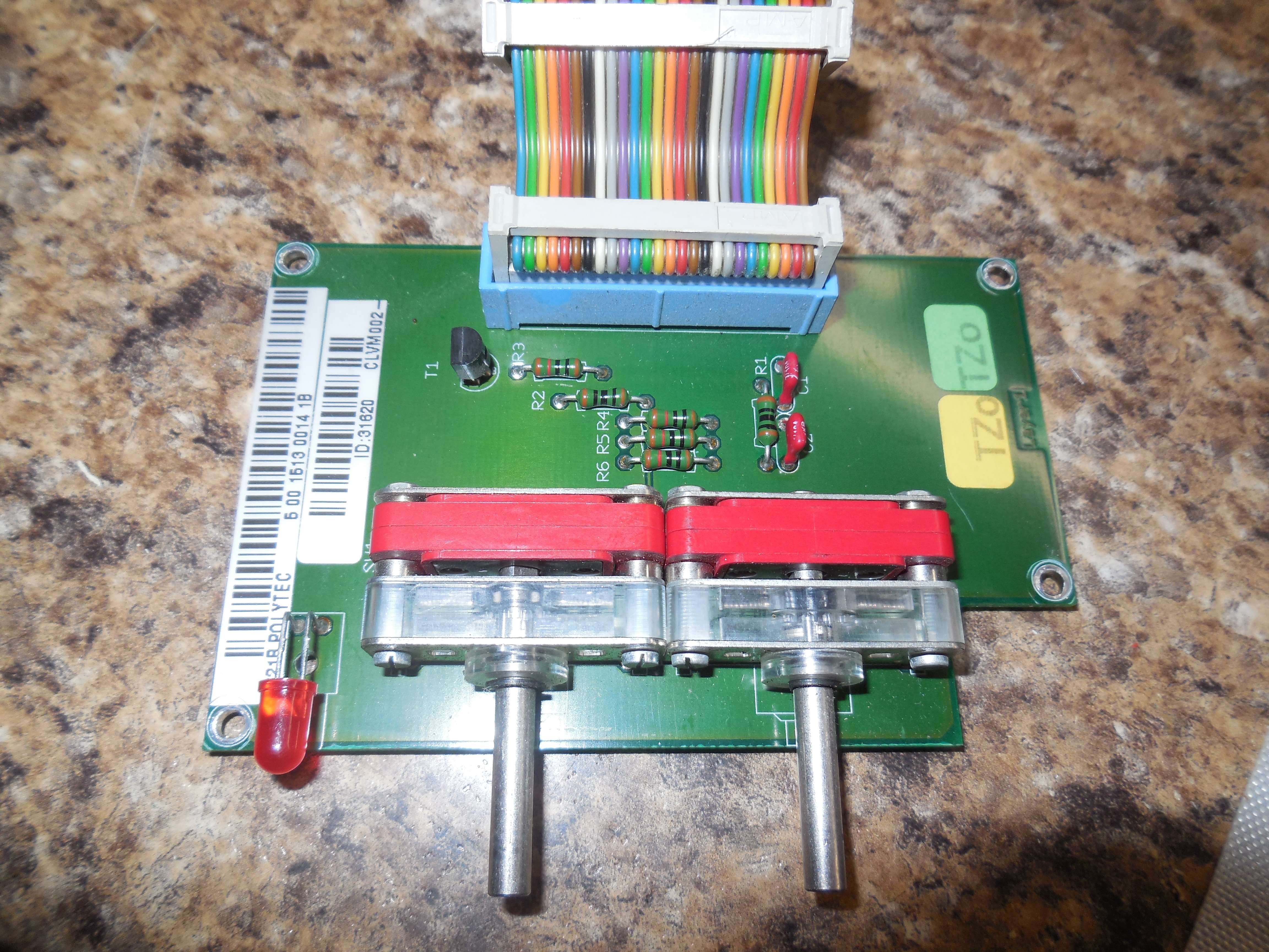
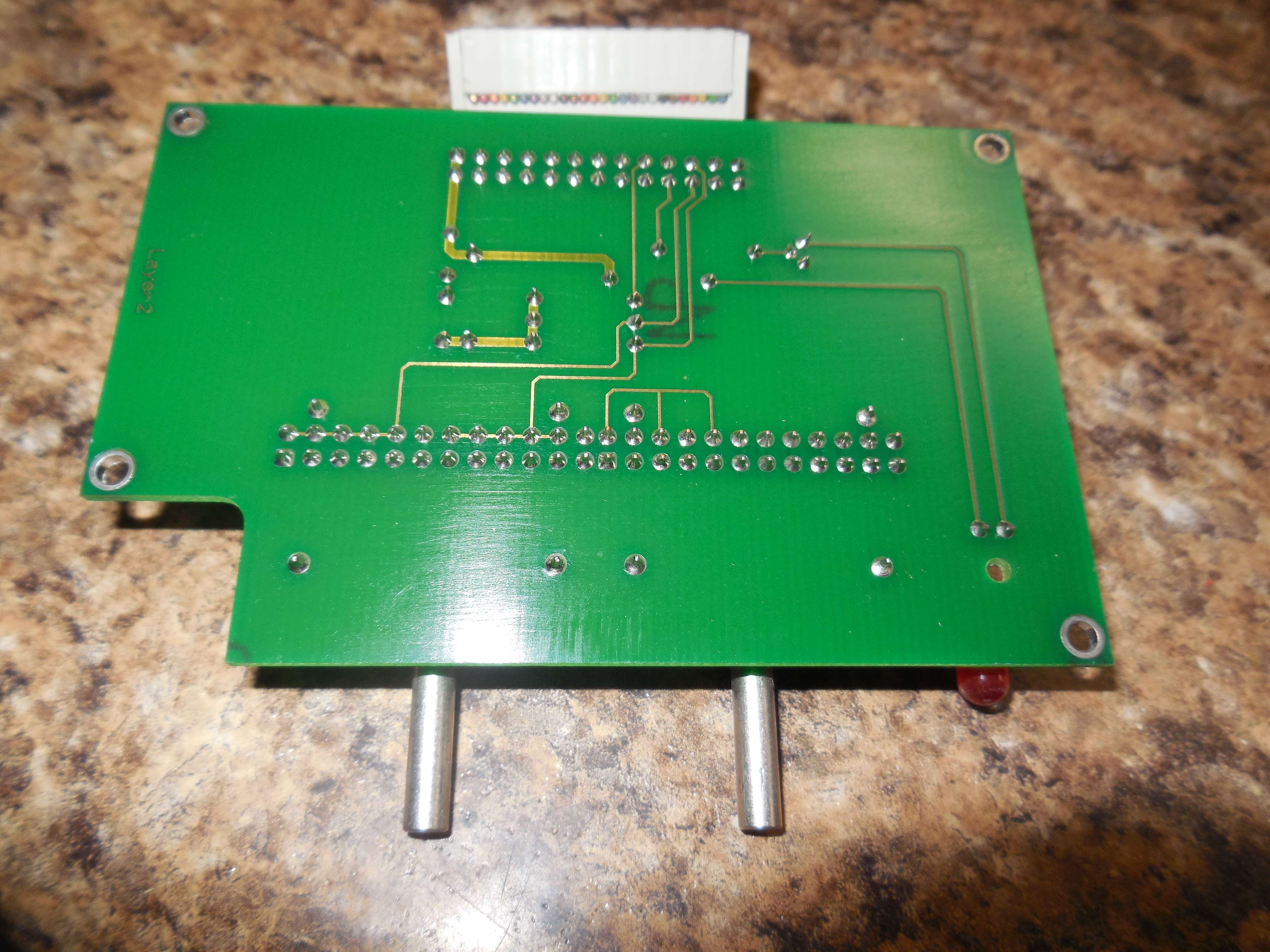
This is from a damaged CLV-M003 Output Module. It is missing U4, an Avens AS2114-10hz 10 Hz high-pass filter.
The CLV-M003 Ouput Module is the same as the CLV-M003 Output Module, except for the addition of the "HP ON/OFF" switch, U4, and U5 (DG419). Also, jumper BR5 is removed on the M003, while it is installed on the M001.
Avens Filters CLV-M001: AS1113-5k, AS1113-20k, AS1113-50k CLV-M003: AS1113-5k, AS1113-15k, AS1113-30k, AS2114-10hz Avens AS1113-series - Low-Pass, 18 dB @ 2Fc Avens AS2114-series - High-Pass, 24 dB @ 0.5Fc |
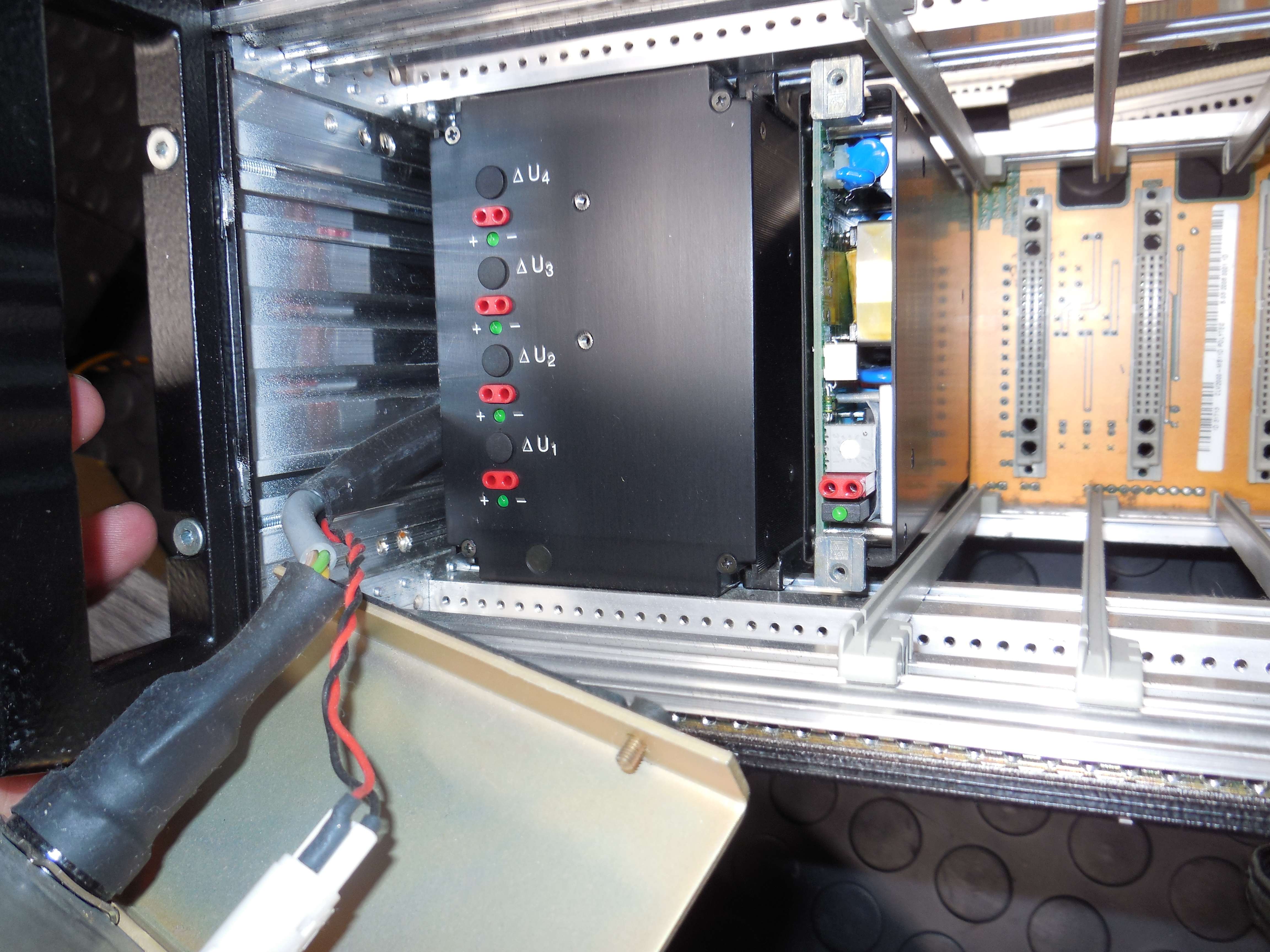
Power Supply Modules
This is a separate -15 VDC power supply for the sensors:
Kniel System-Electronic GmbH
Typ: CPW 15.0,8
A.-Nr.: 303-011-09 .00
U in: 90-264Vac 45-440Hz
I in max.: 0,5A
This is the main power supply for the modules:
Kniel System-Electronic GmbH
Typ: PWQ 1601
A.-Nr.: 274-602-04 .03
U in: 90-264Vac 45-440Hz
I in max.: 2,5A
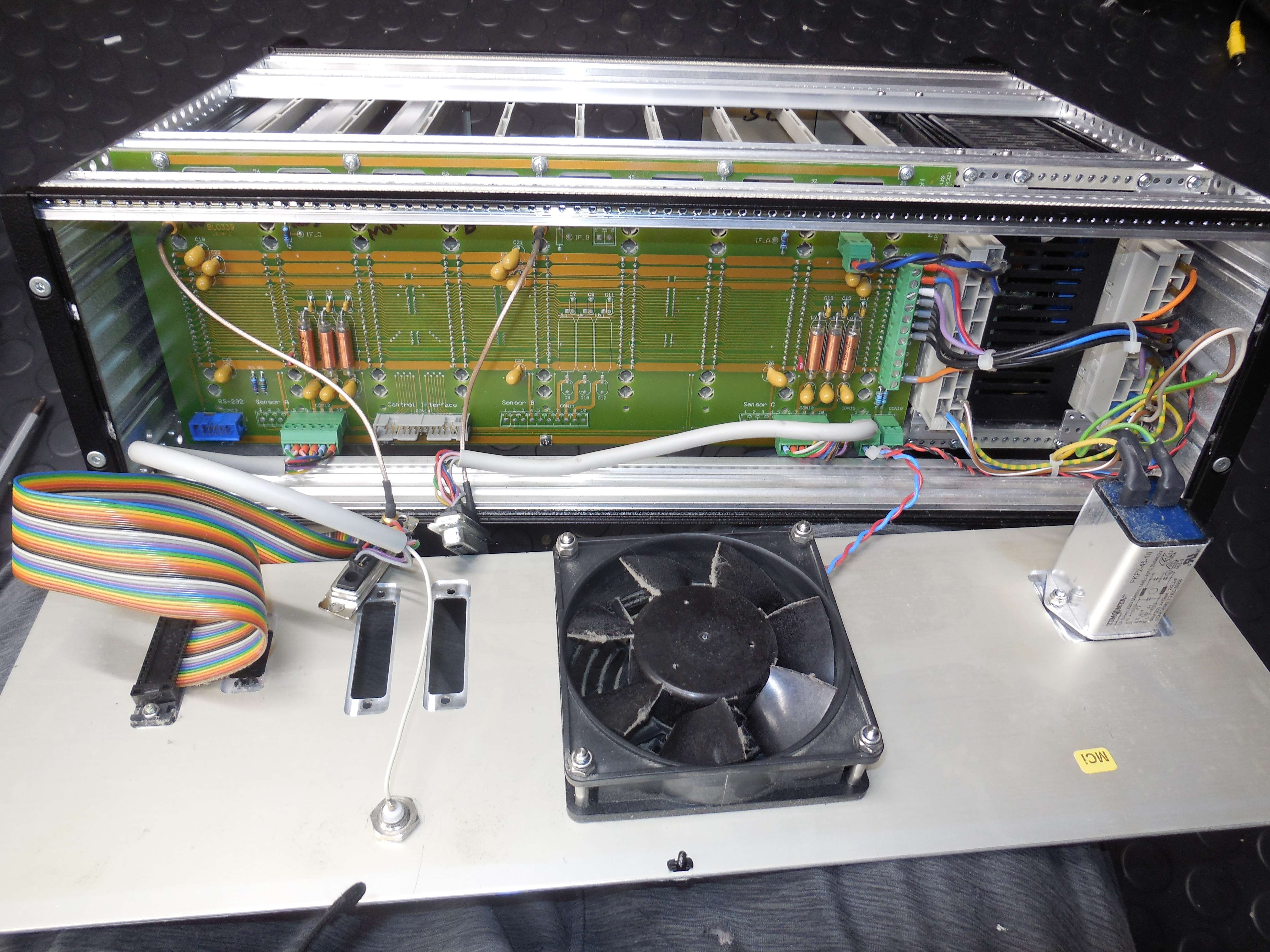
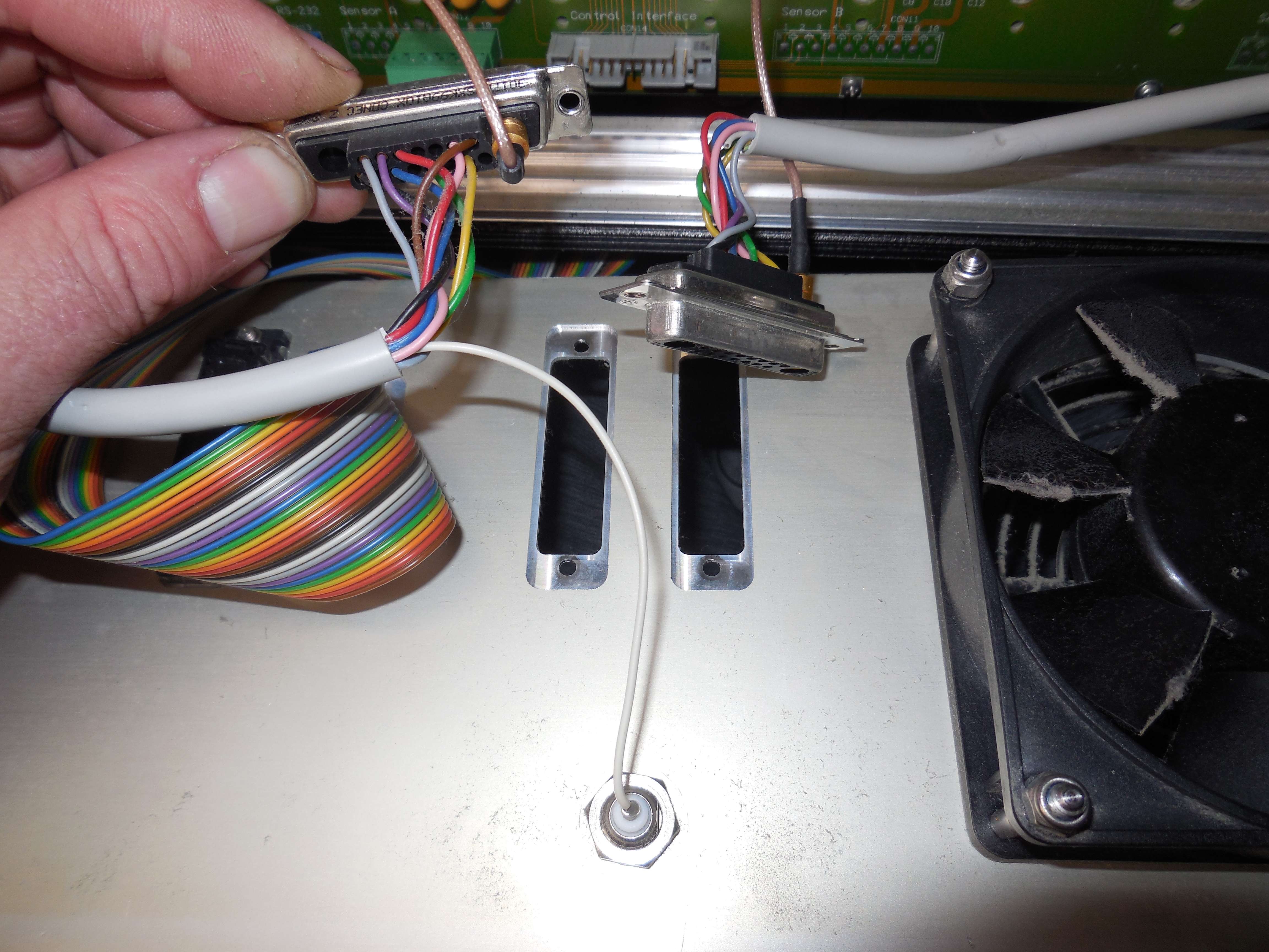
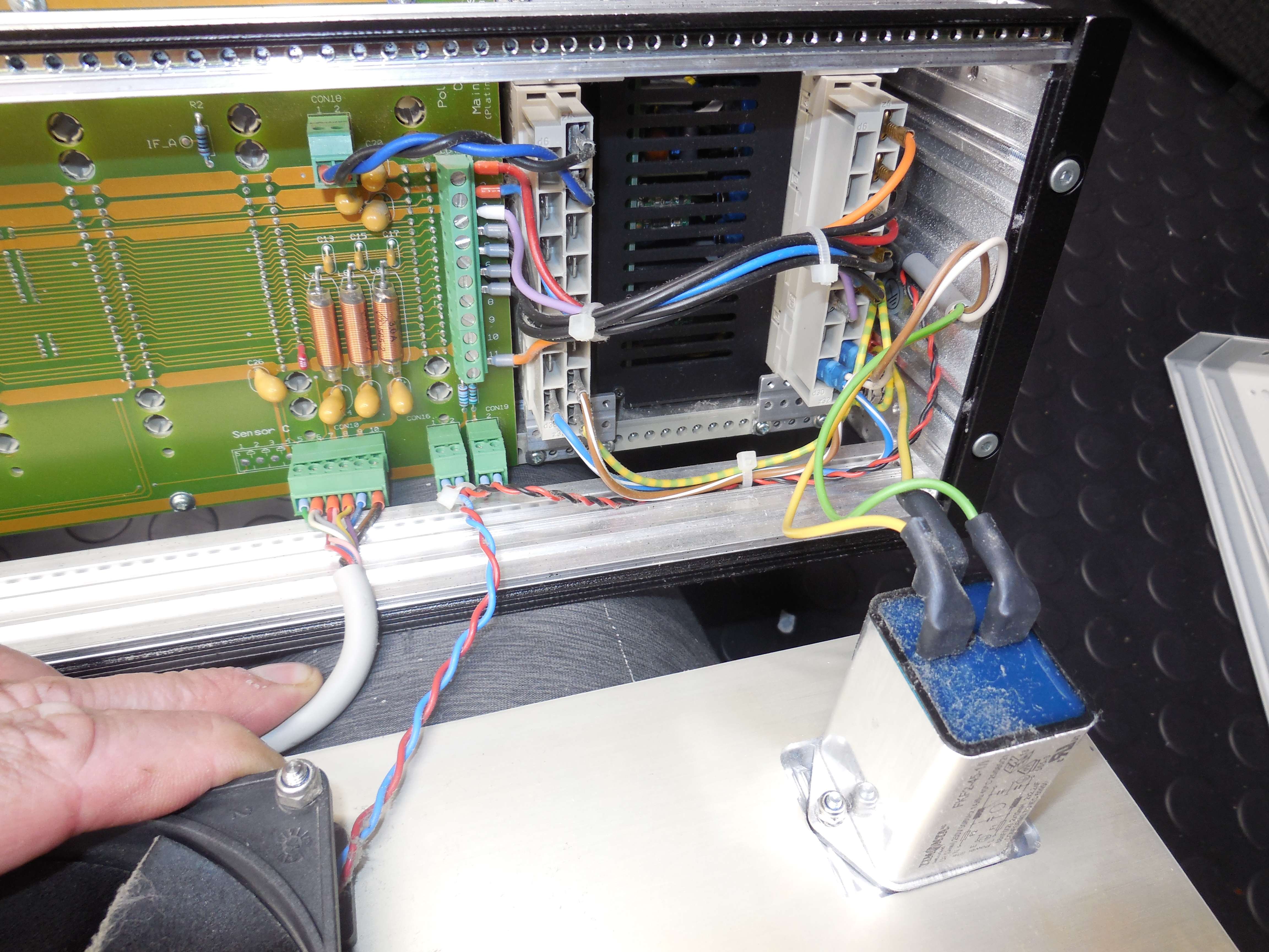
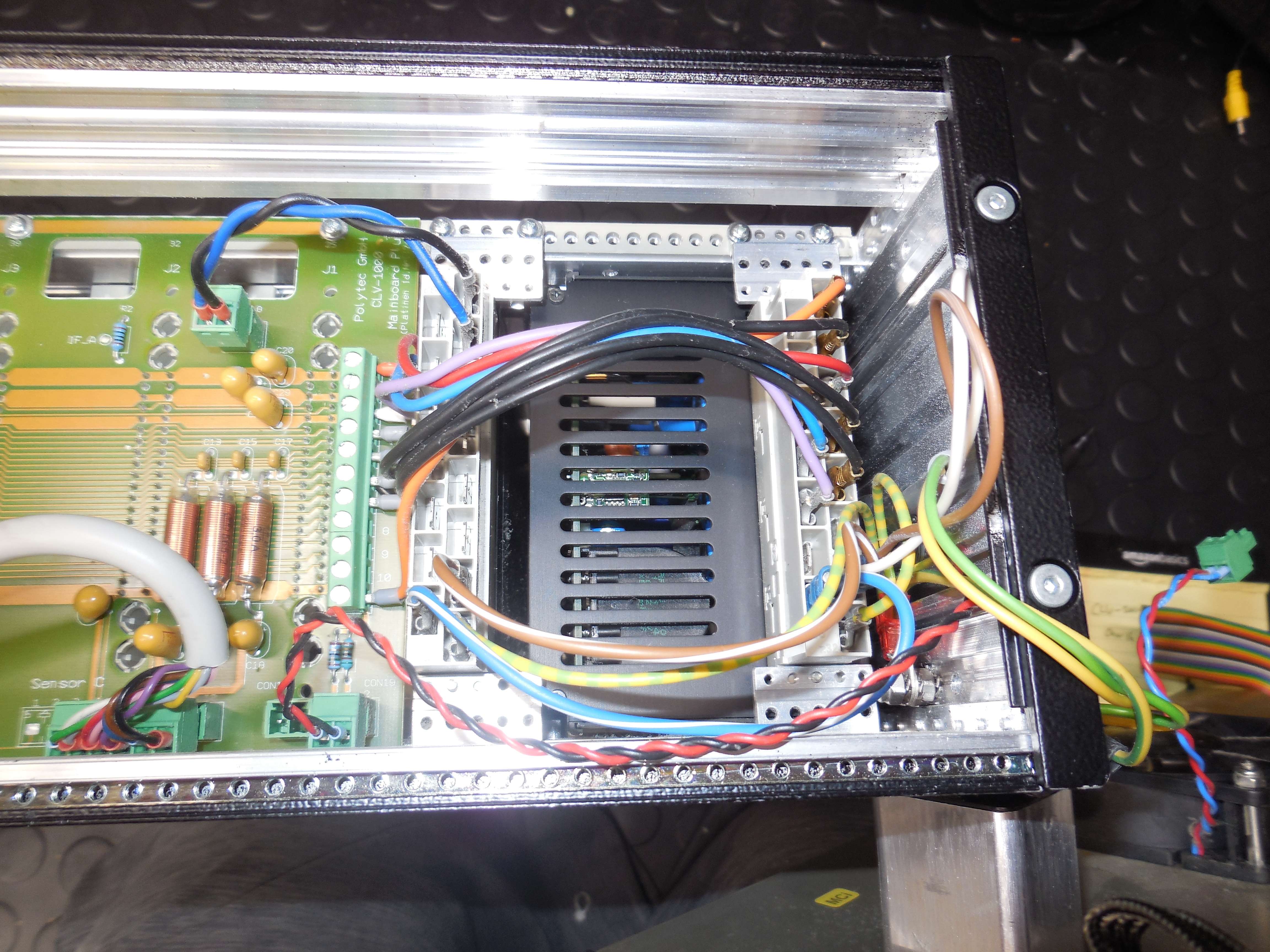
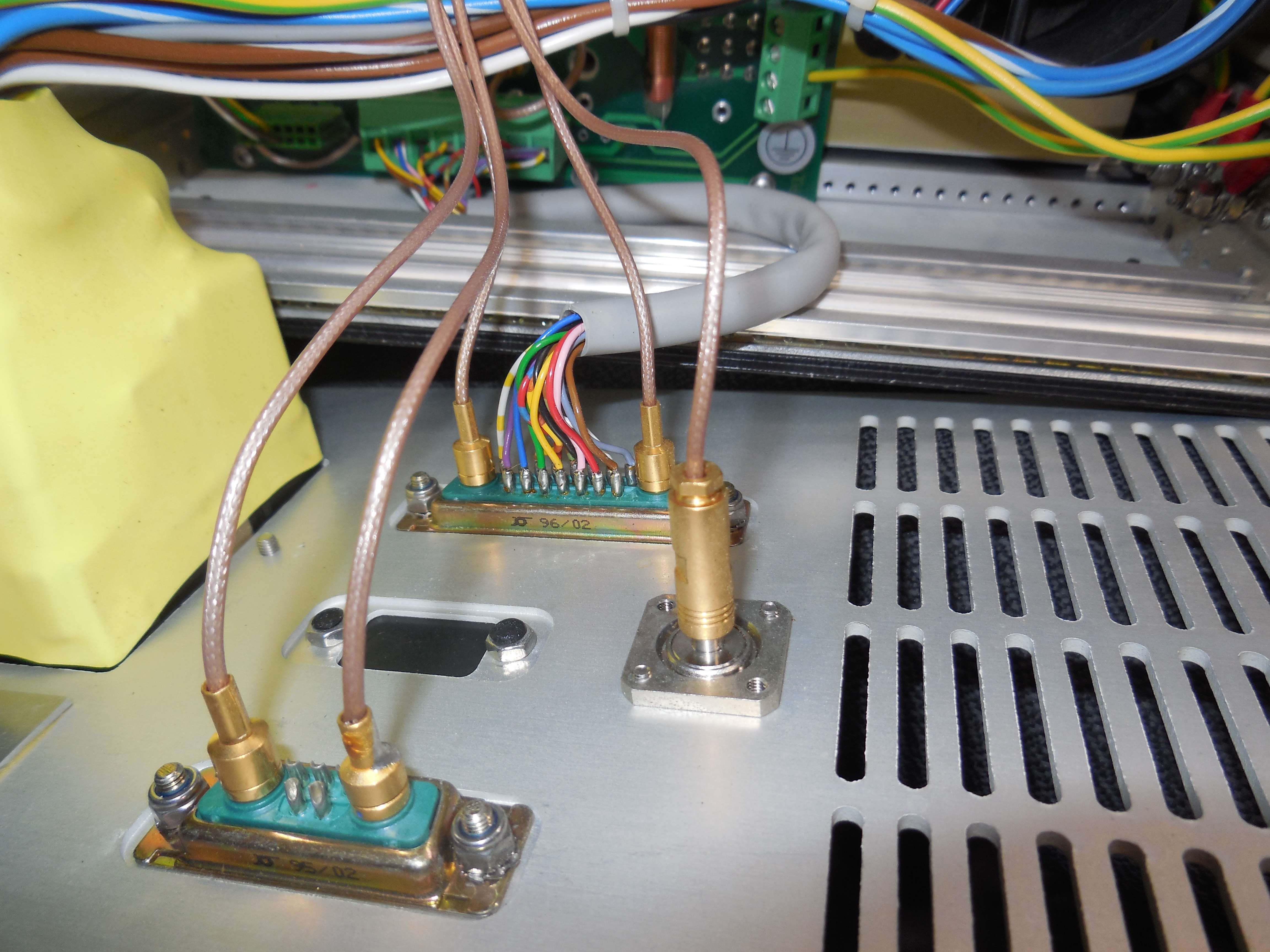
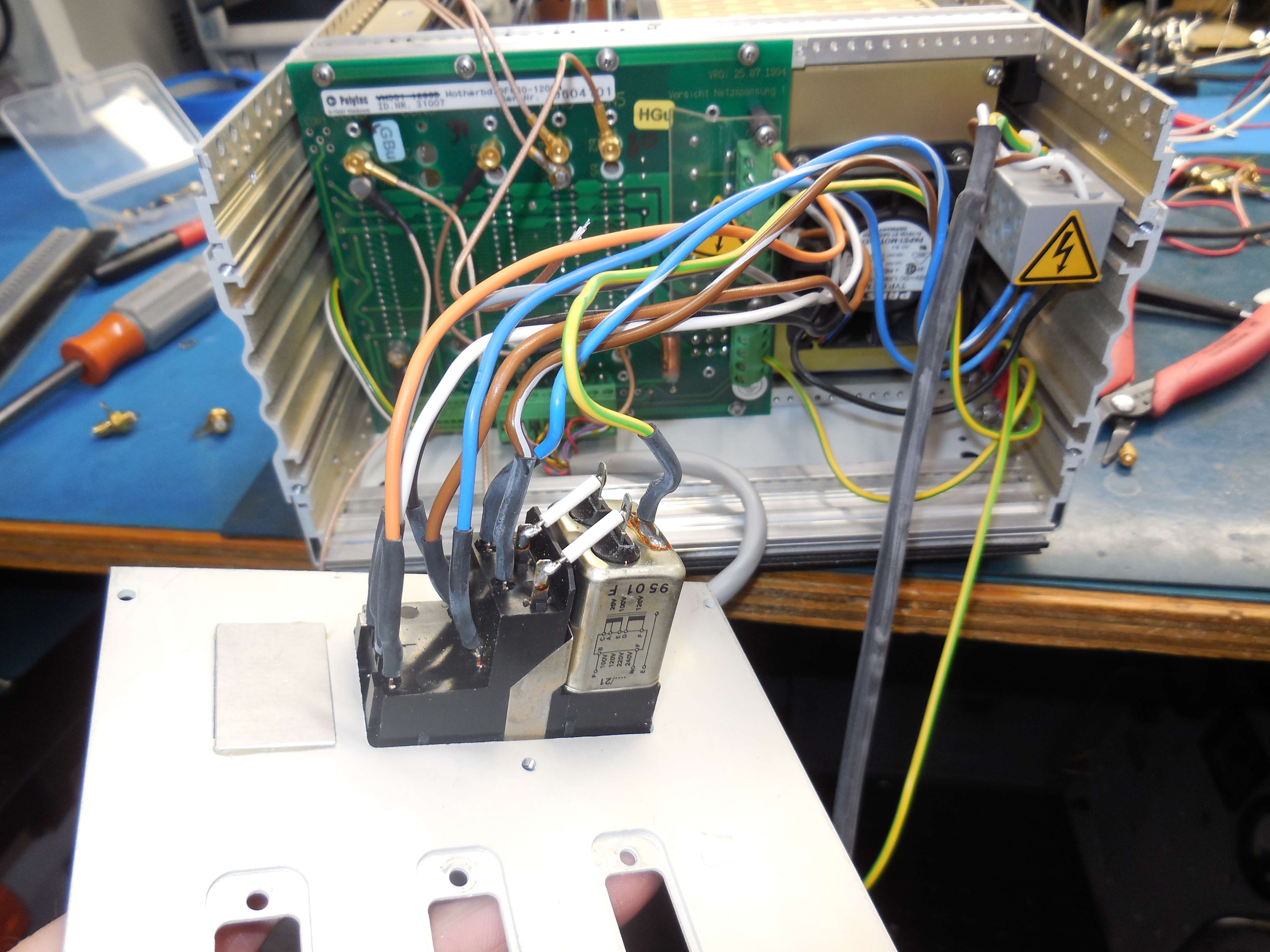
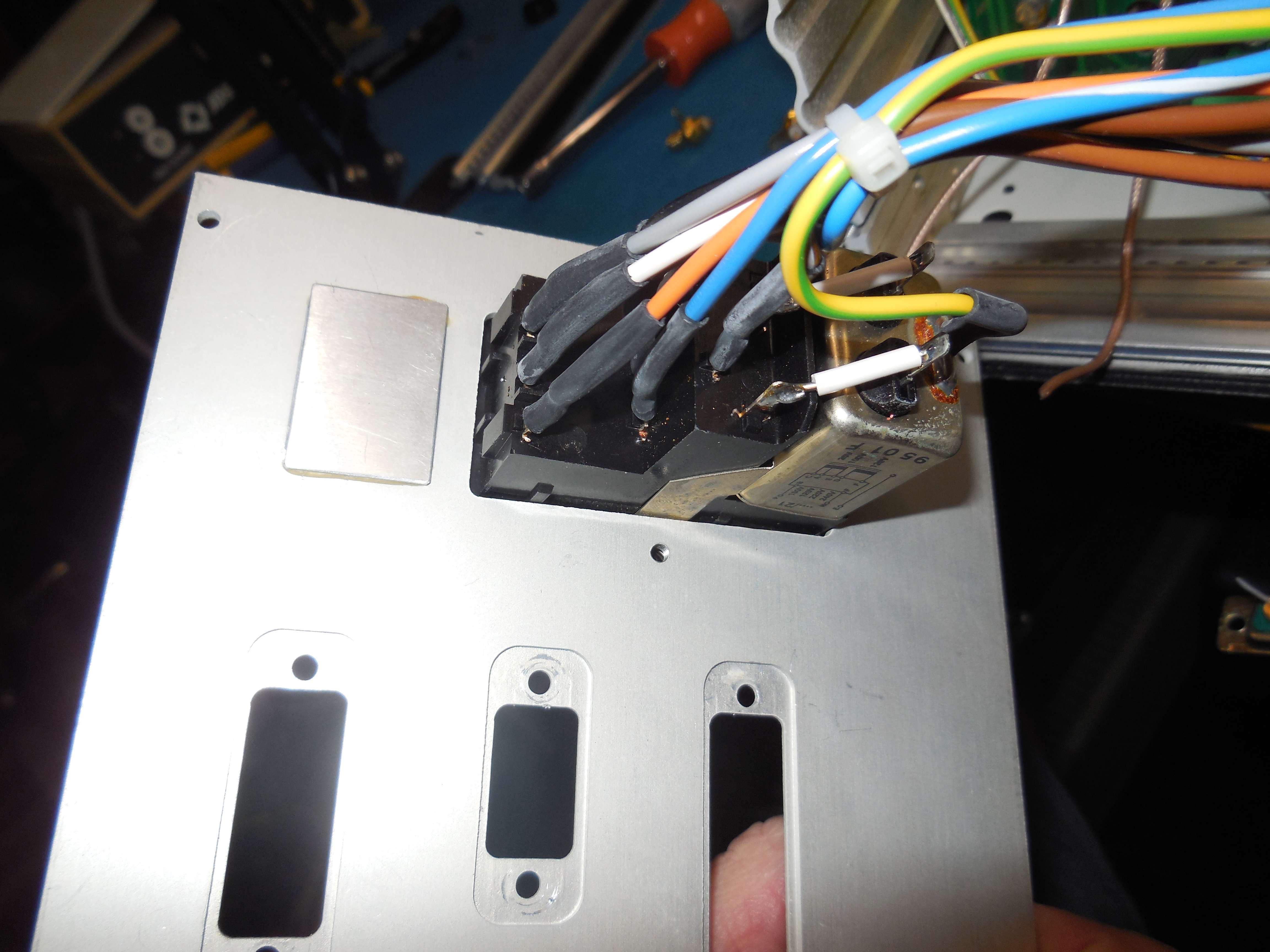
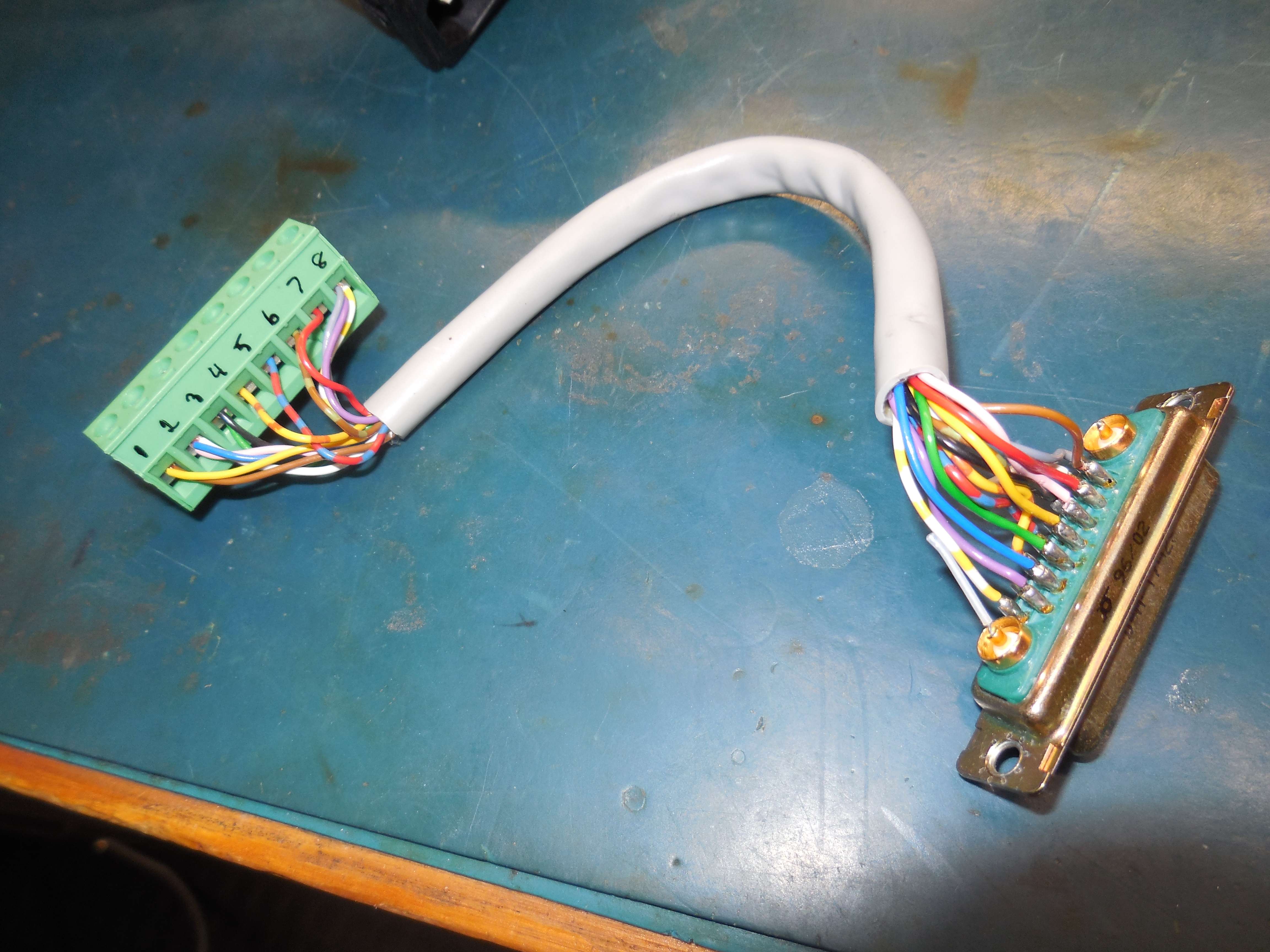
Sensor Connectors
Rear-Panel: Sensor Input (3017W2SXK99A10X)
A1: No Connection
A2: Coaxial - Signal Input
1: Grey
2: Violet (+5 VDC)
3: Red (+15 VDC)
4: No Connection
5: No Connection
6: Pink (+15 VDC)
7: Brown
8: Black
9: No Connection
10: Blue (-15 VDC)
11: No Connection
12: Green
13: No Connection
14: Yellow (+5 VDC)
15: No Connection
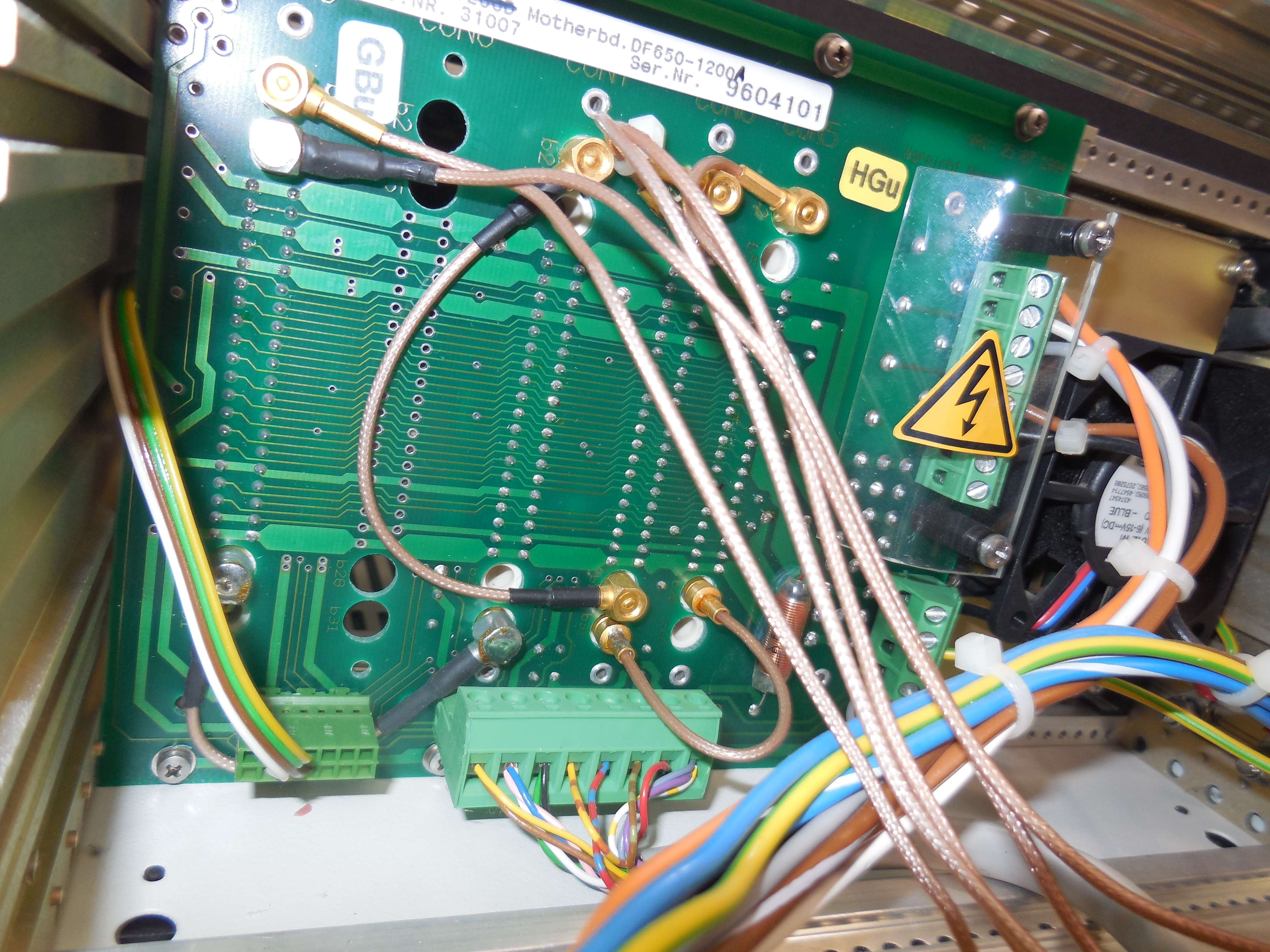
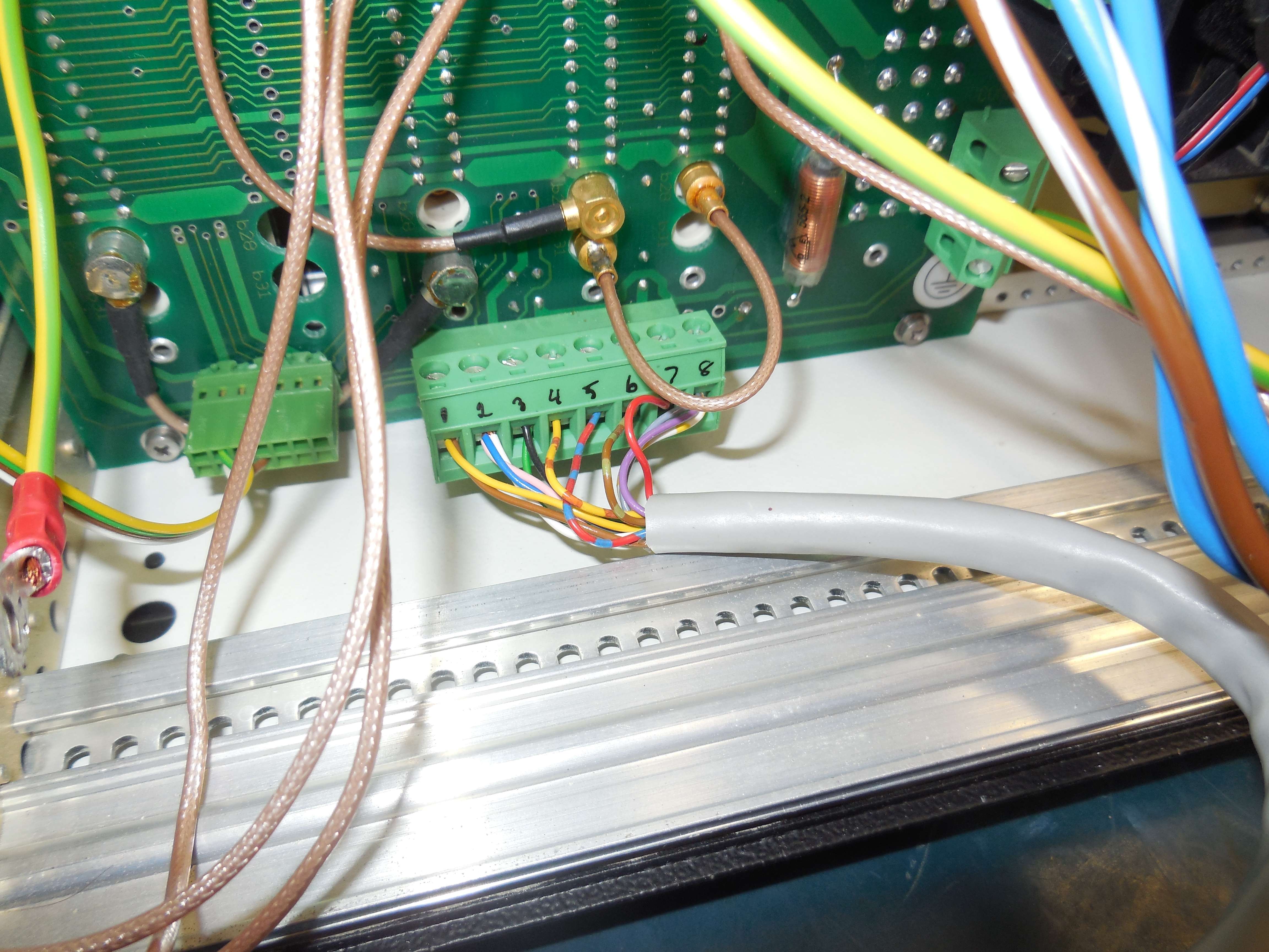
Green Terminals on Mainboard (CON10/CON12)
1: No Connection
2: No Connection
3: No Connection
4: No Connection
5: Green
6: White & Grey
7: Red & Pink (+15 VDC)
8: Violet & Yellow (+5 VDC)
9: Blue (-15 VDC)
10: Brown & Black (Ground)
White wire goes to rear-panel Trigger Output (BNC)
Main Power Supply (CON15)
1: +15 VDC (Red)
2: -15 VDC (Blue)
3: -5 VDC (Violet)
4: Ground (Black)
5: Ground (Black)
6: Ground (Black)
7: Ground (Black)
8: No Connection
9: No Connection
10: No Connection
11: +5 VDC (Orange)
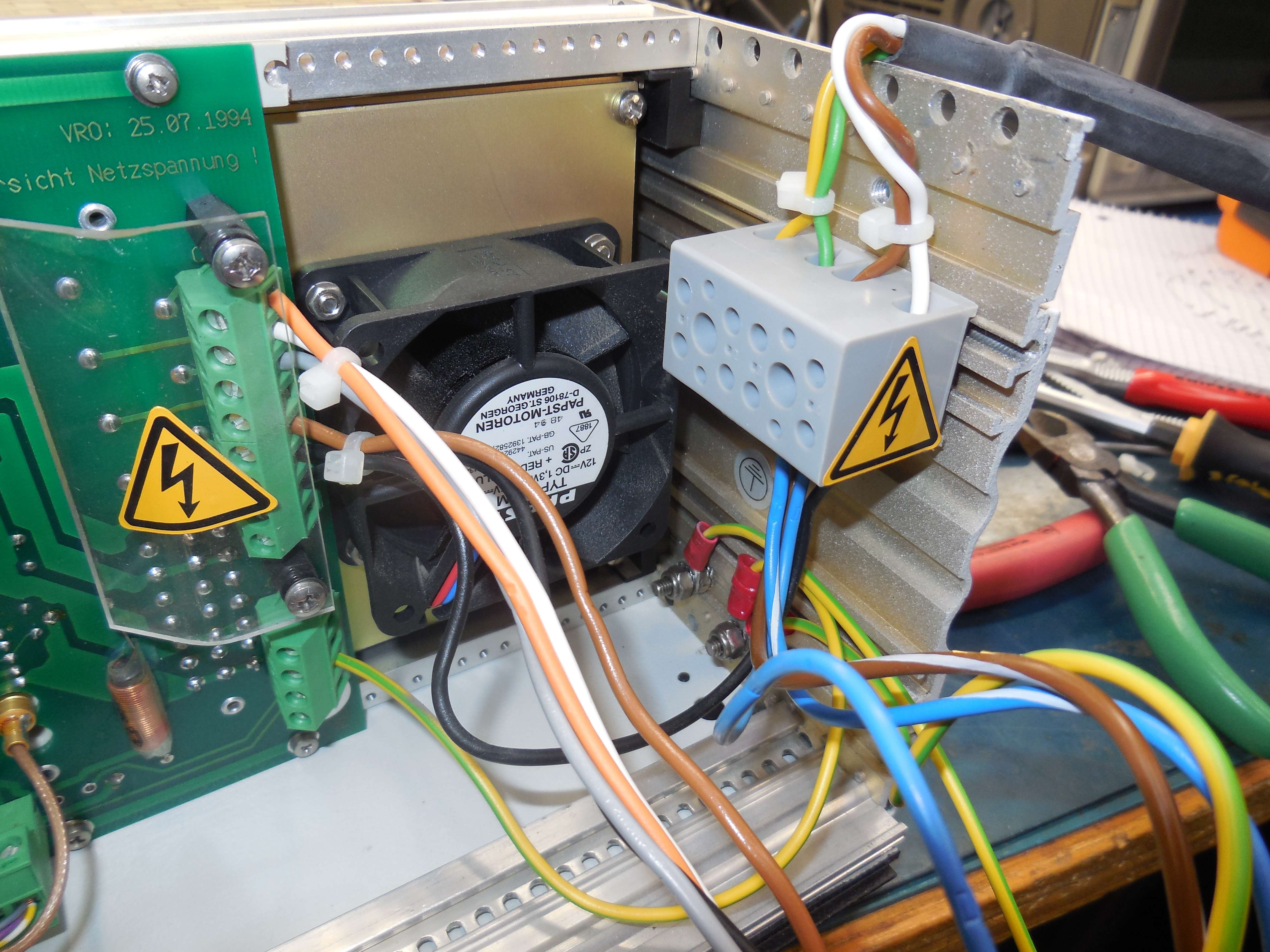
CON16: +15 VDC for fan
CON18: -15 VDC SENSOR - input from power supply module
CON19: +15 VDC for front-panel power light
|
OFV-3000 Vibrometer Controller
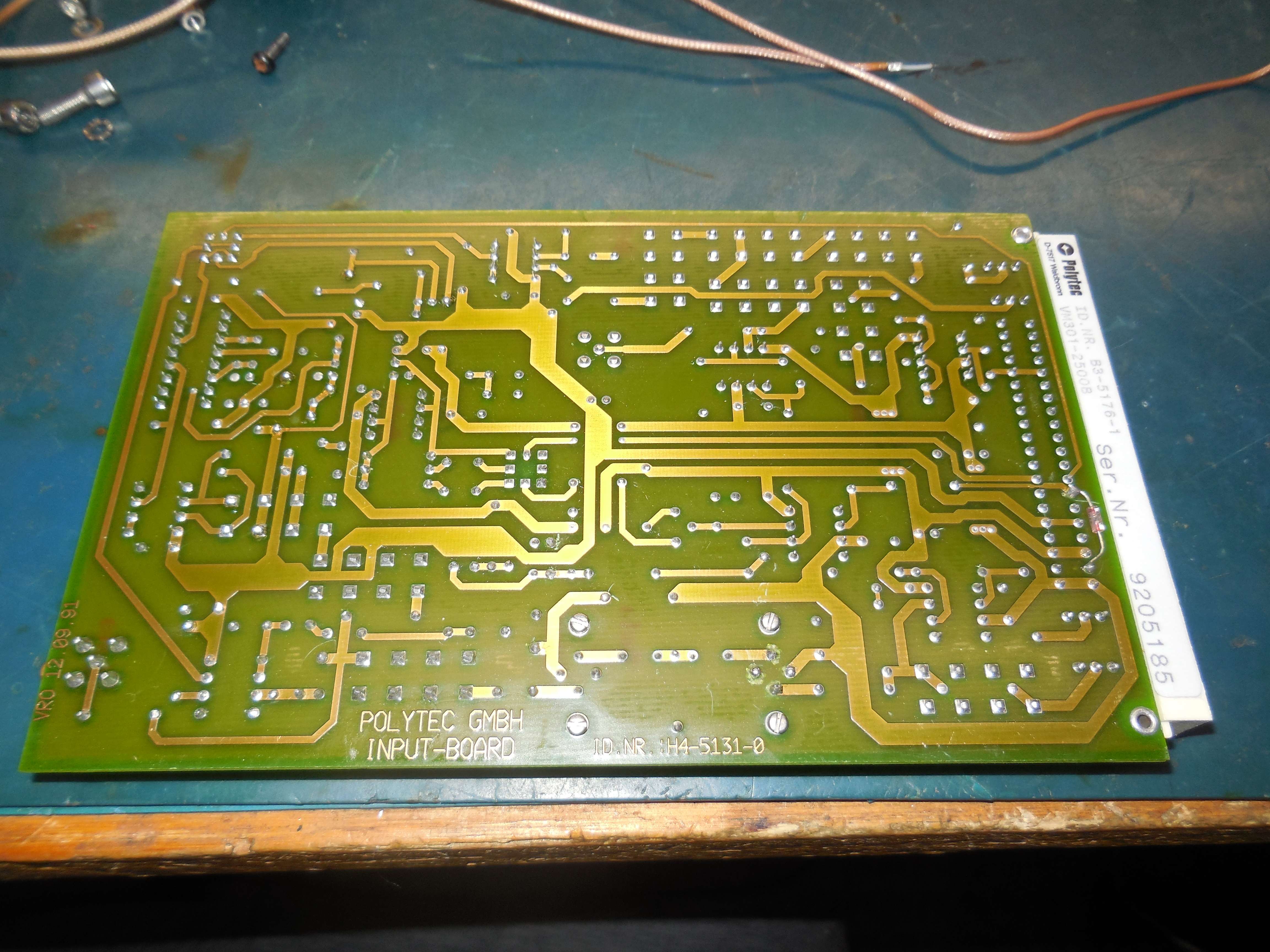
VM301-2500B Input Board
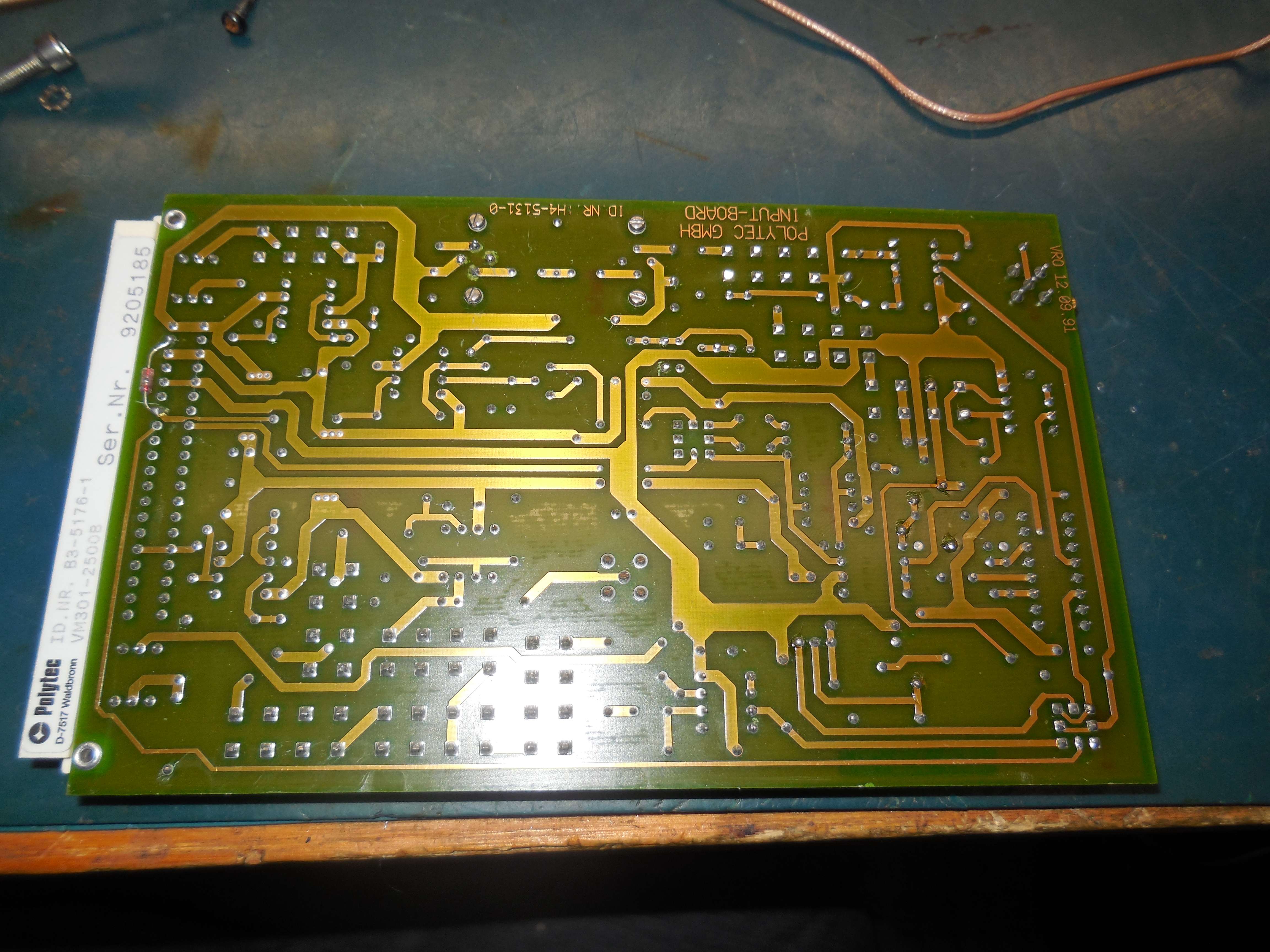
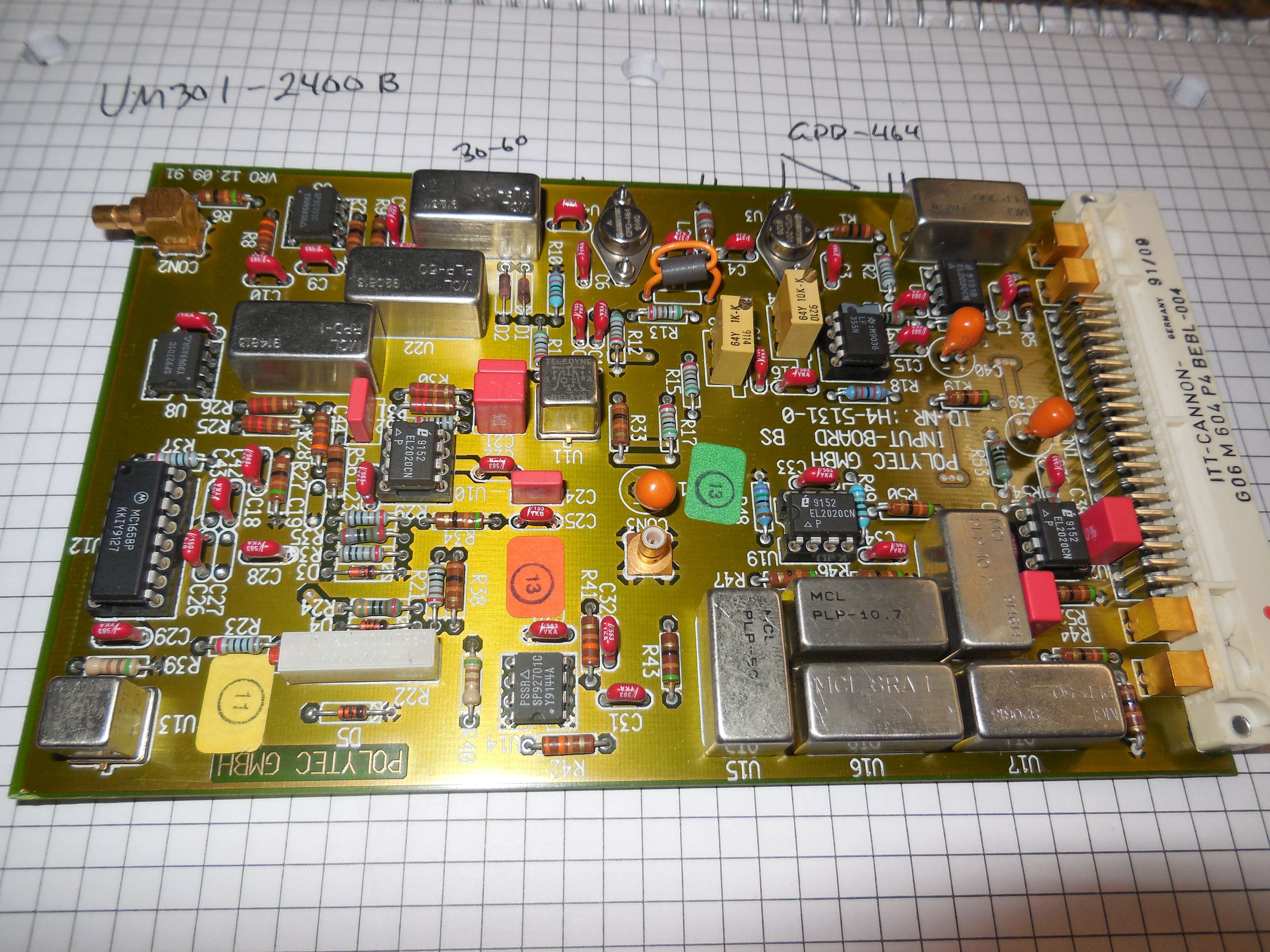
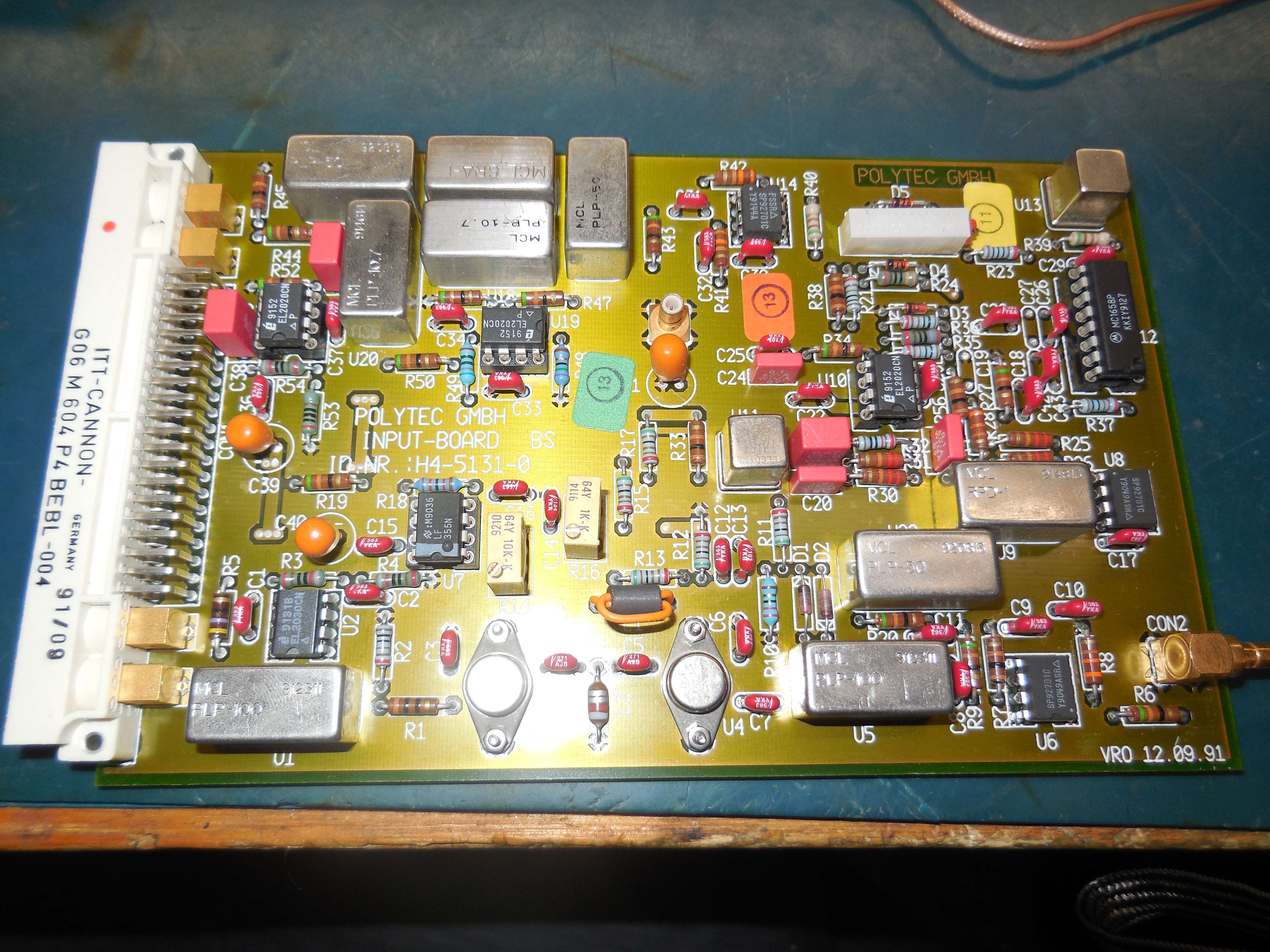
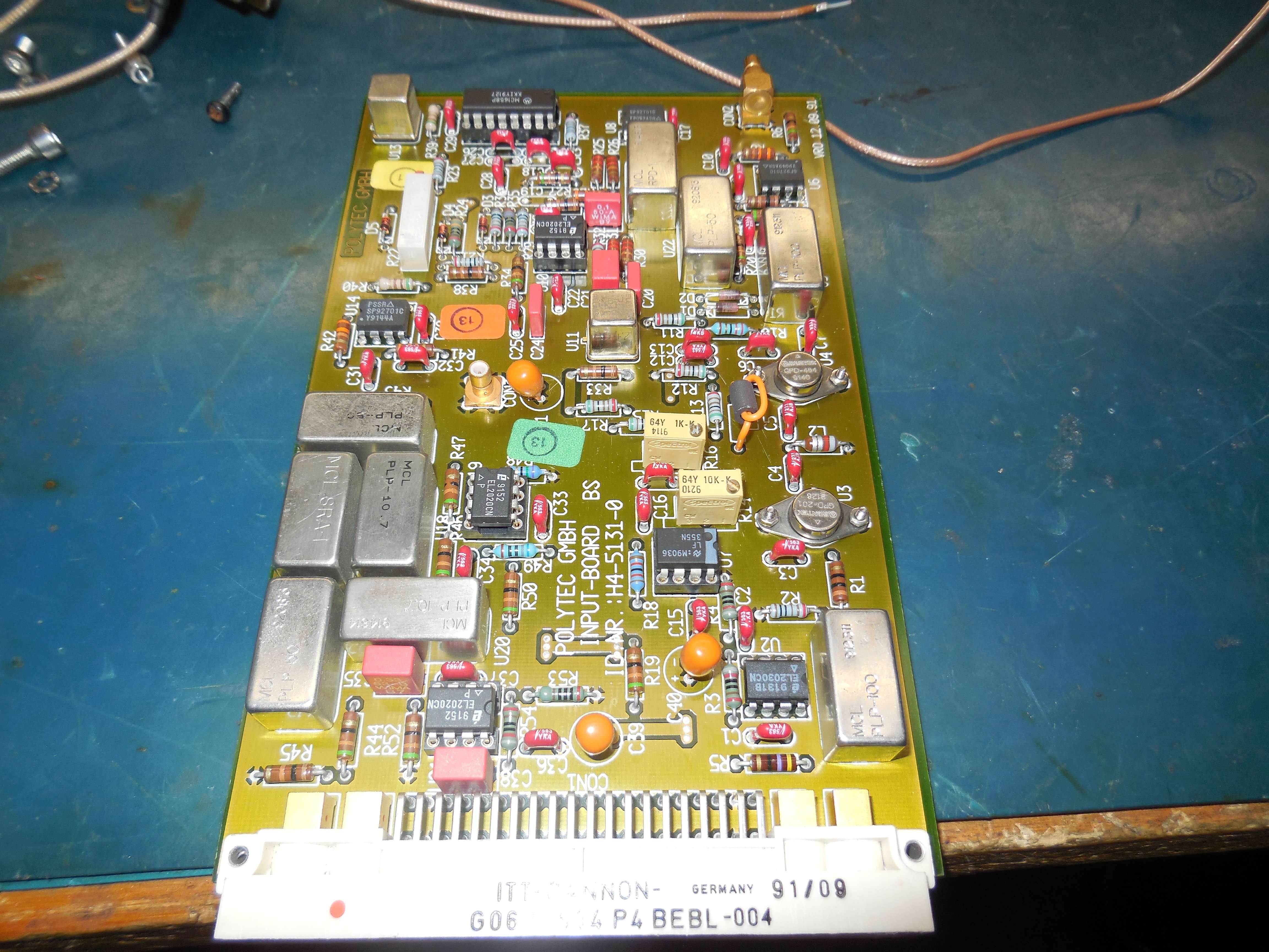
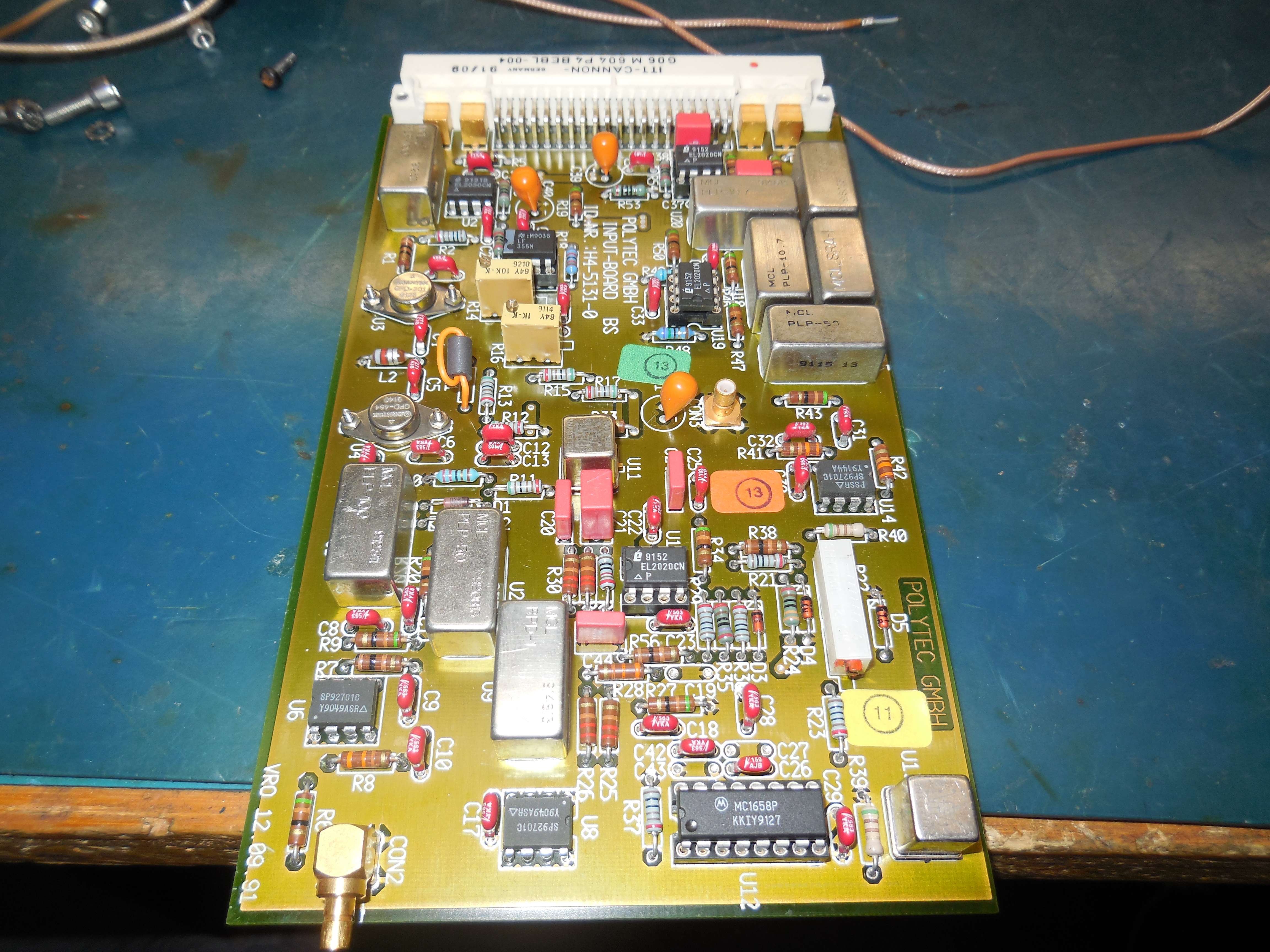
Avantek GPD-464, Avantek GPD-201, LF355, MC10H131, MC10H016, MCL RPD-1, MCL PLP-100, EL2030, MCL PLP-10.7, MCL SRA-1, EL2020, MCL PLP-50, SP92701, MC1658
The SP92701 feeds pins 7 & 8 on the RPD-1. The input to the SP92701 is from MC1658 pin 4.
VM301-2400C Output Board
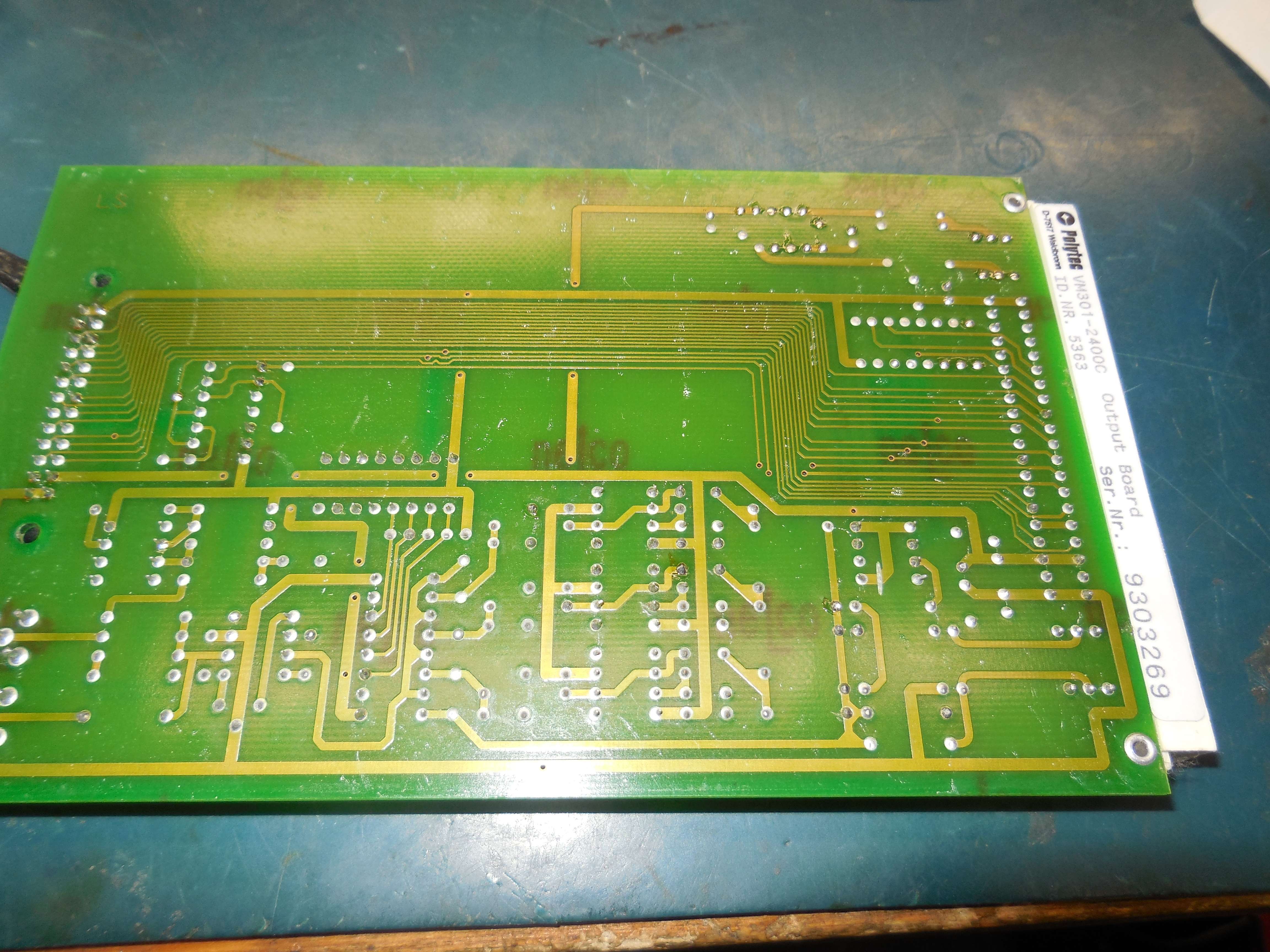
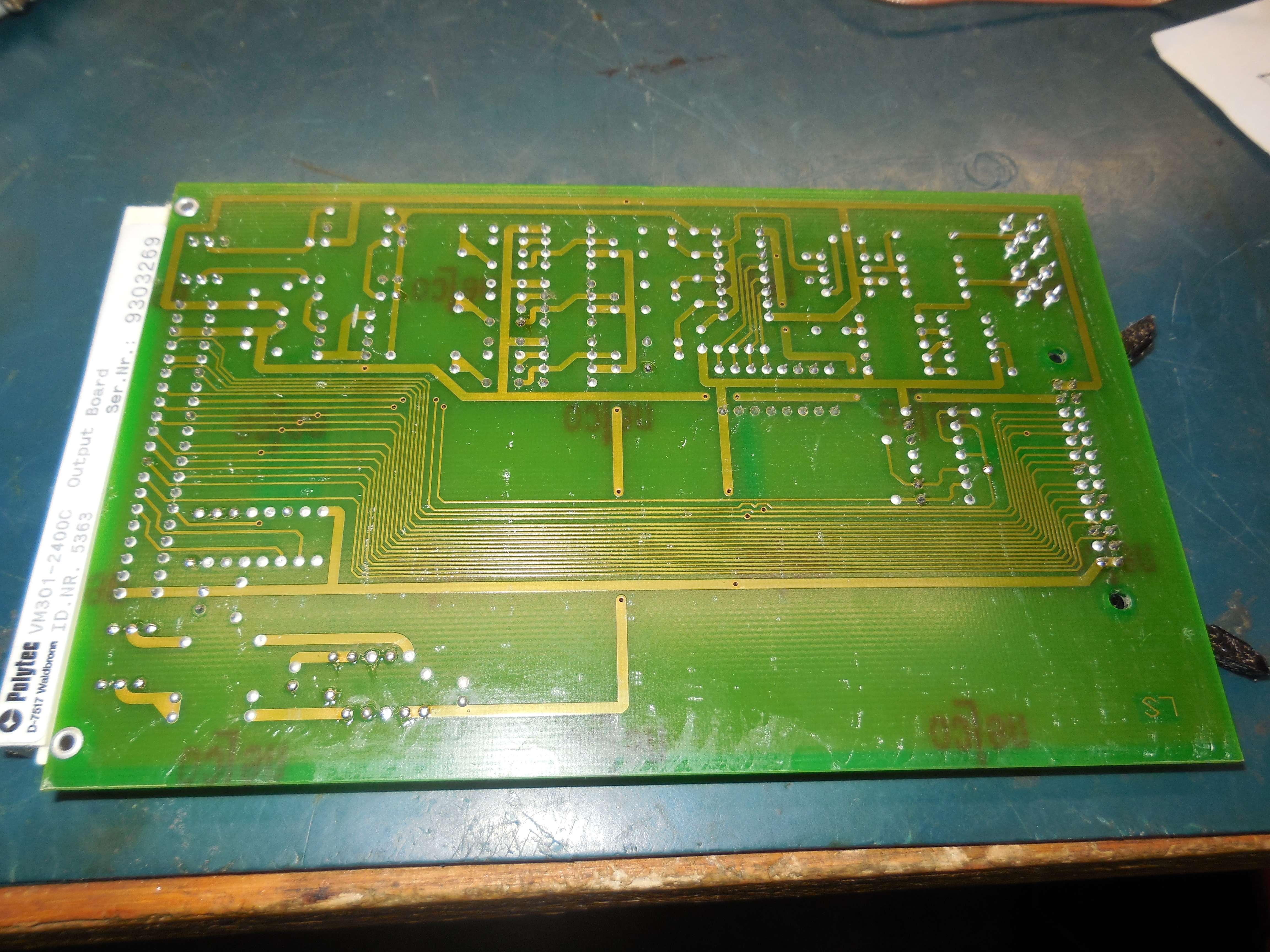
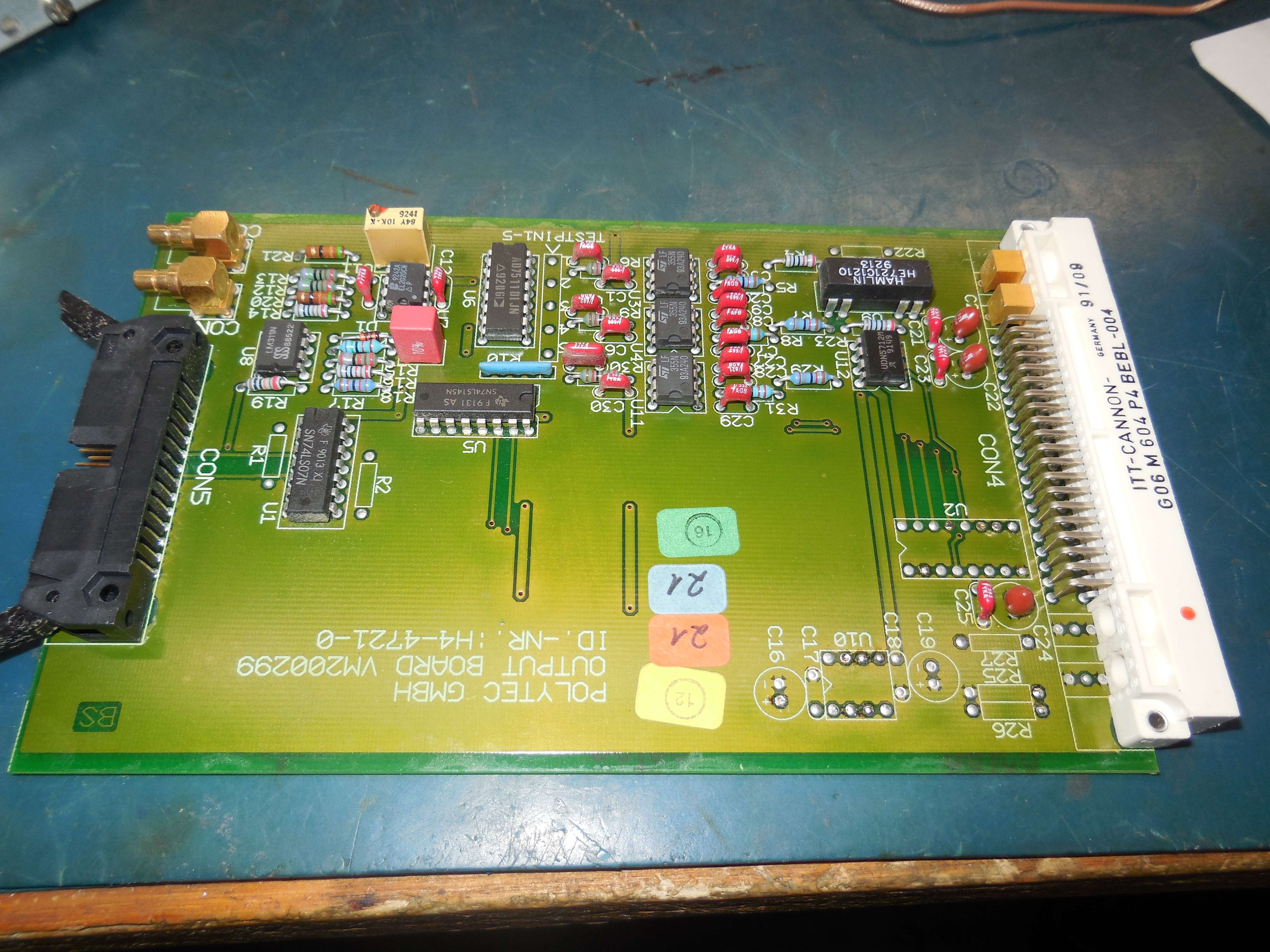
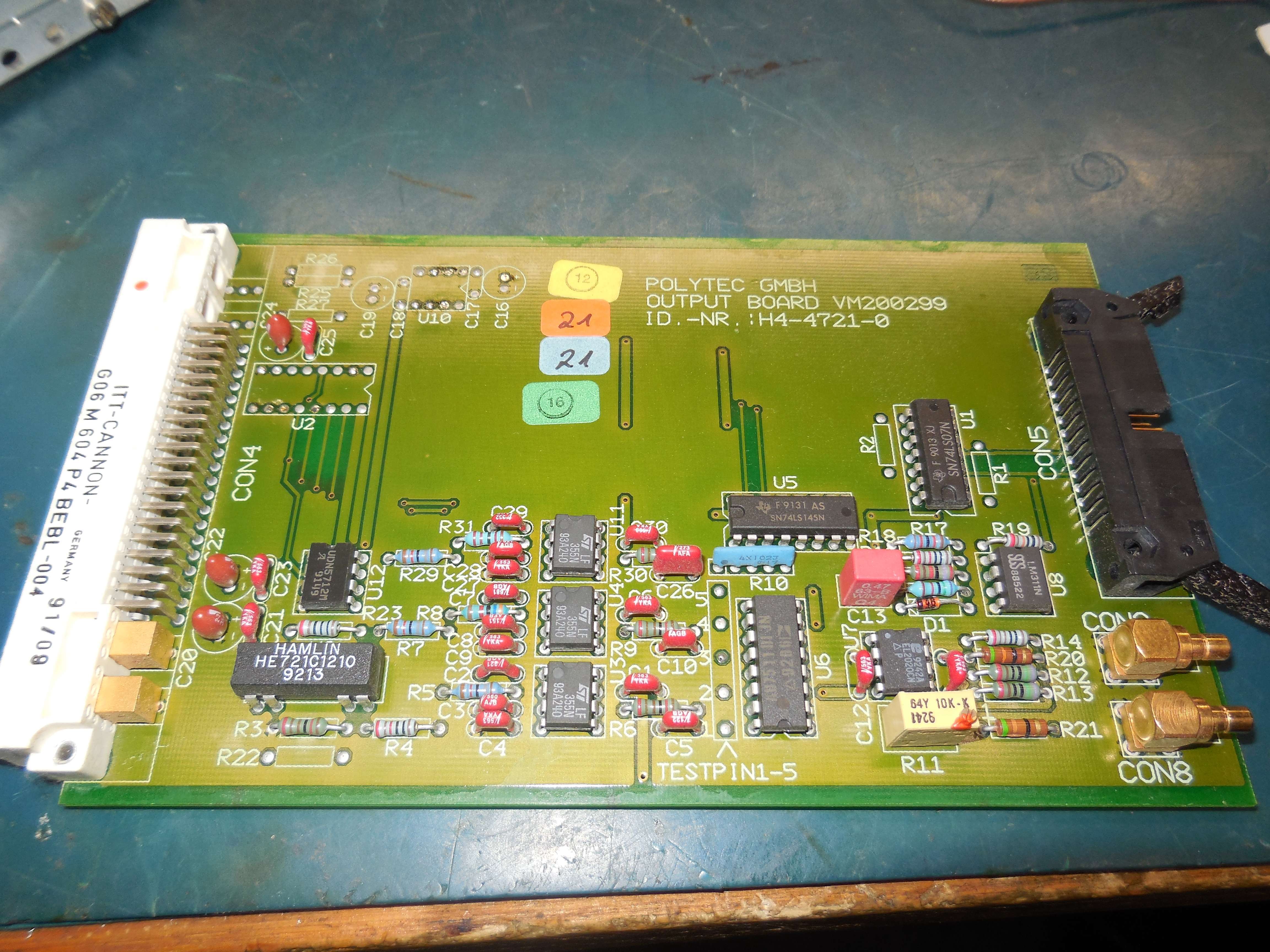
AD7511, Hamlin HE721C1210 relay, Sprague UDN5712M power drivers.
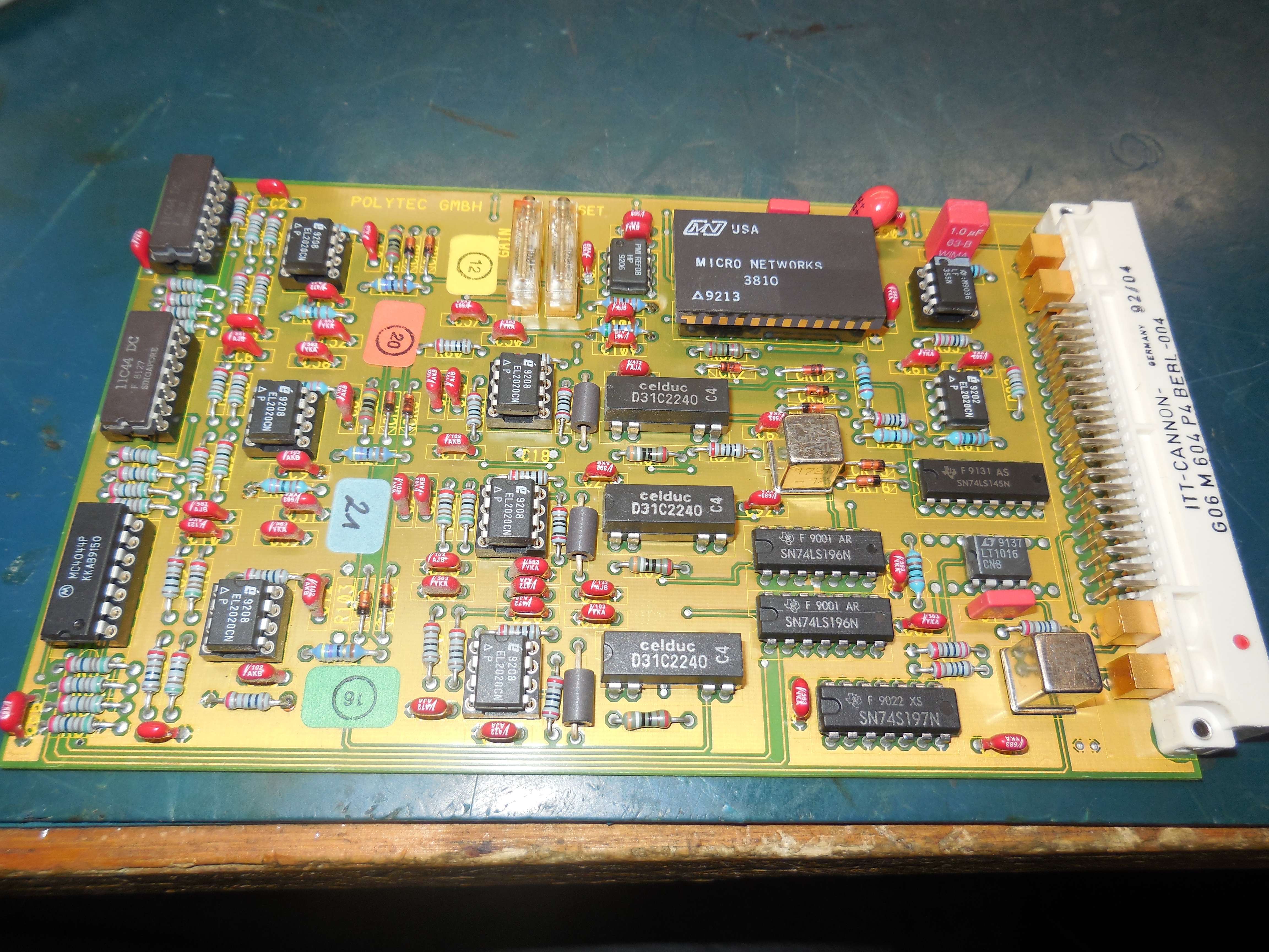
VM301-6000E PLL Velocity Board (w/ Fringe Counter Outputs) (OVD-01)
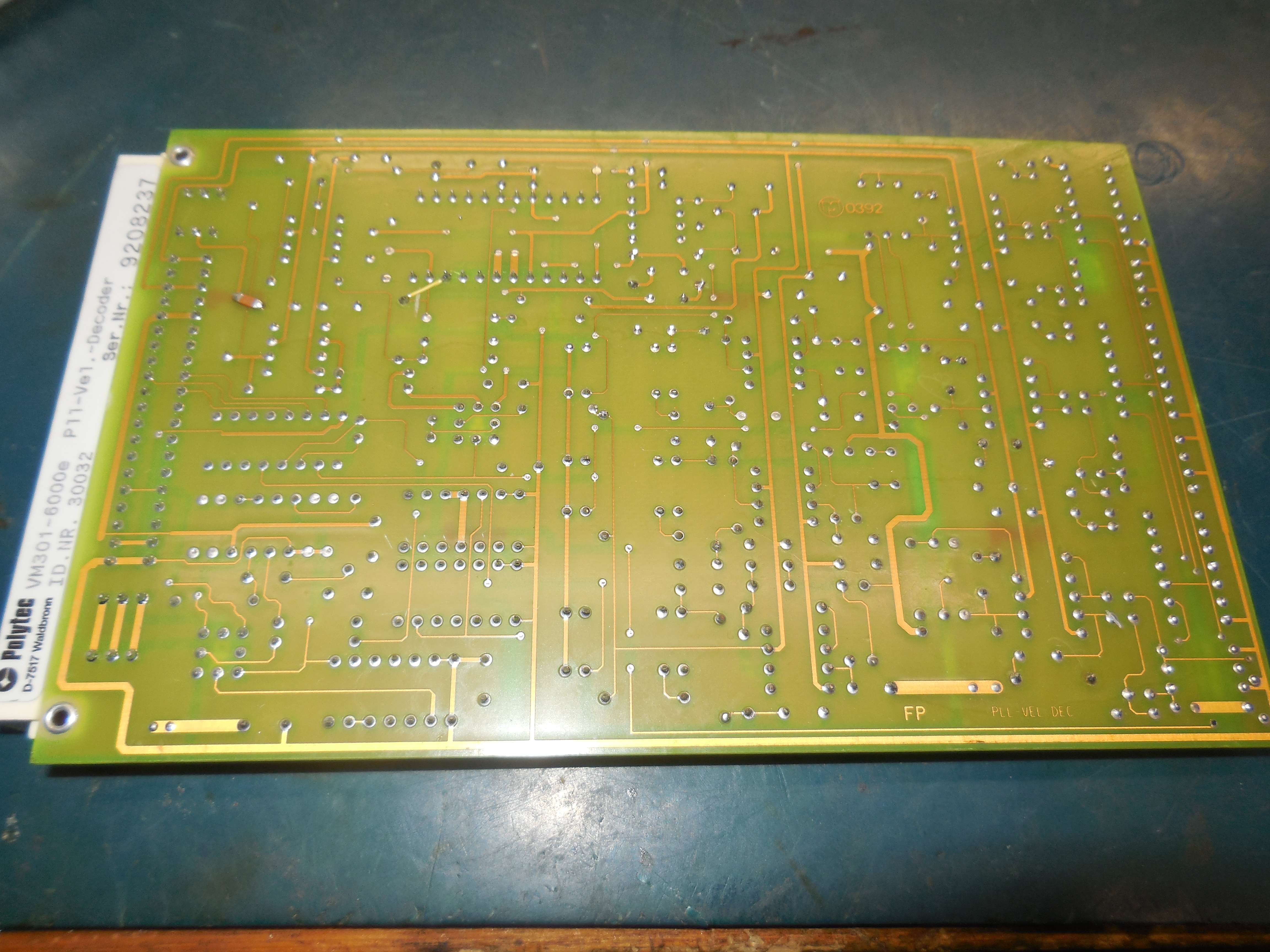
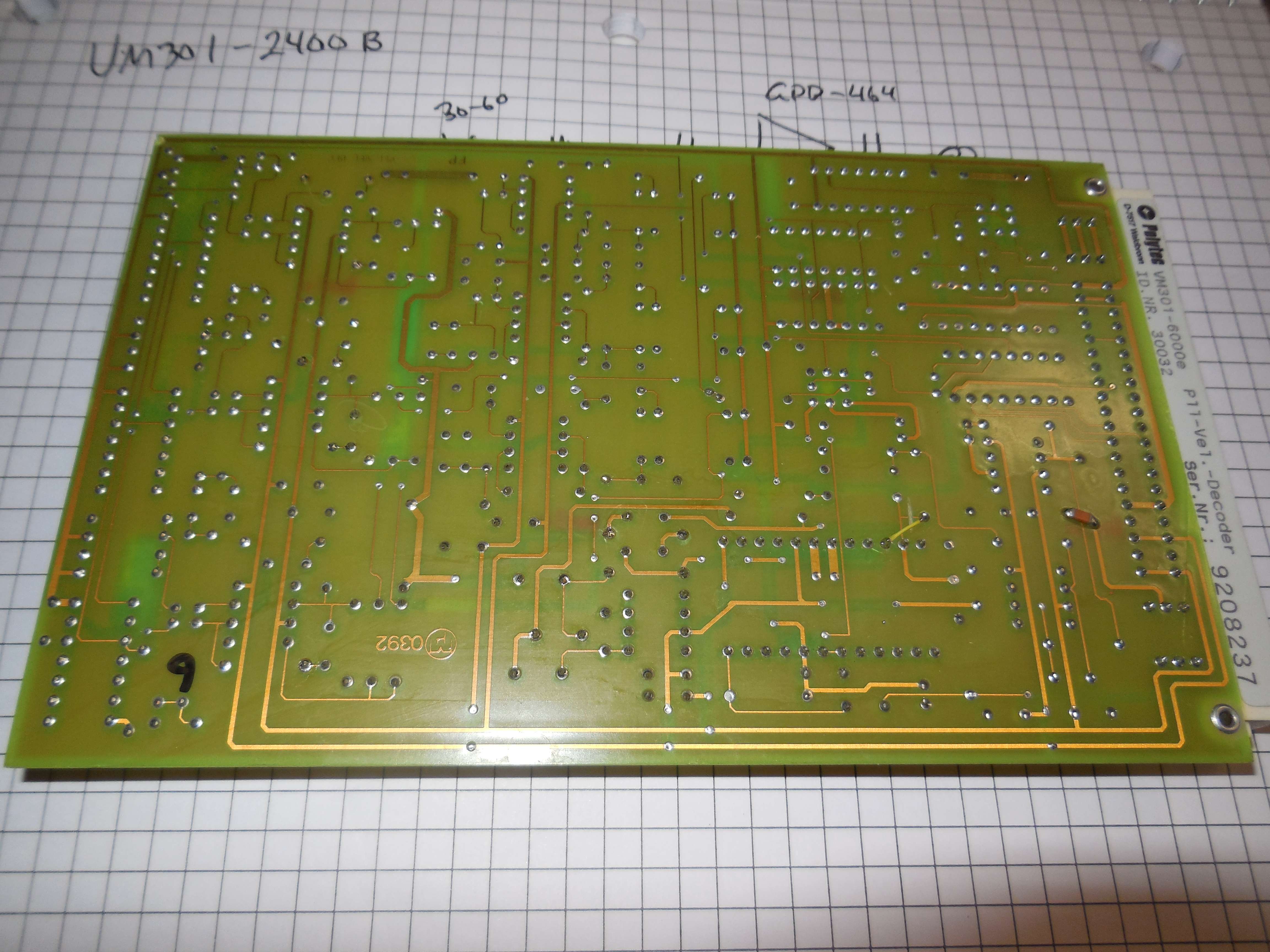
The Polytec OVD-01 is a velocity output module which plugs into the OFV-3001 modular controller. It consists of one printed circuit board. The OVD-01 uses a special PLL decoding scheme which converts the Doppler signal from the optical sensor into a calibrated velocity output. The OVD-01 is characterized by it's very high linearity (0.5%) and low noise level. The maximum operating frequency is 50 kHz. There are 5 different velocity ranges to choose from: 10 mm/s, 50 mm/s, 250 mm/s, 1.25 m/s and 10 m/s full scale peak.
The OVD-01 is a velocity decoder for applications in the acoustic frequency range up to approximately 20 kHz. In this range, it has excellent linearity and accuracy characteristics. With five measurement ranges from 1 mm/s/V to 1,000 mm/s/V it covers the full dynamic range of the vibrometer with high resolution. The upper four measurement ranges can be used up to frequencies of 50 kHz and higher while retaining their good characteristics, however amplitude accuracy and linearity decrease with higher frequencies. The measurement ranges 125 mm/s/V and 1,000 mm/s/V can be used from the frequency 0 Hz (full DC capabilit).
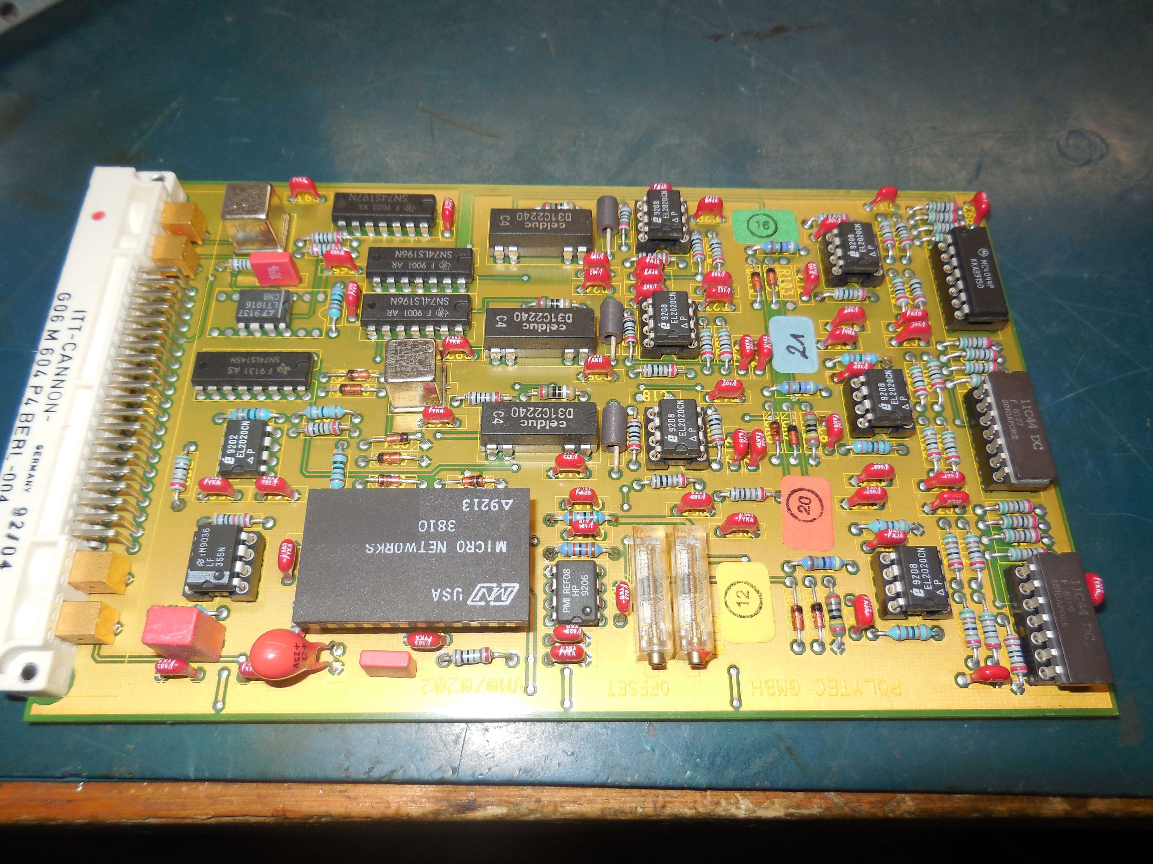
11C44, Micro Networks MD3810 (volt-to-freq), MC4044, EL2020, LT1016, LF355, REF08 (-10V ref)
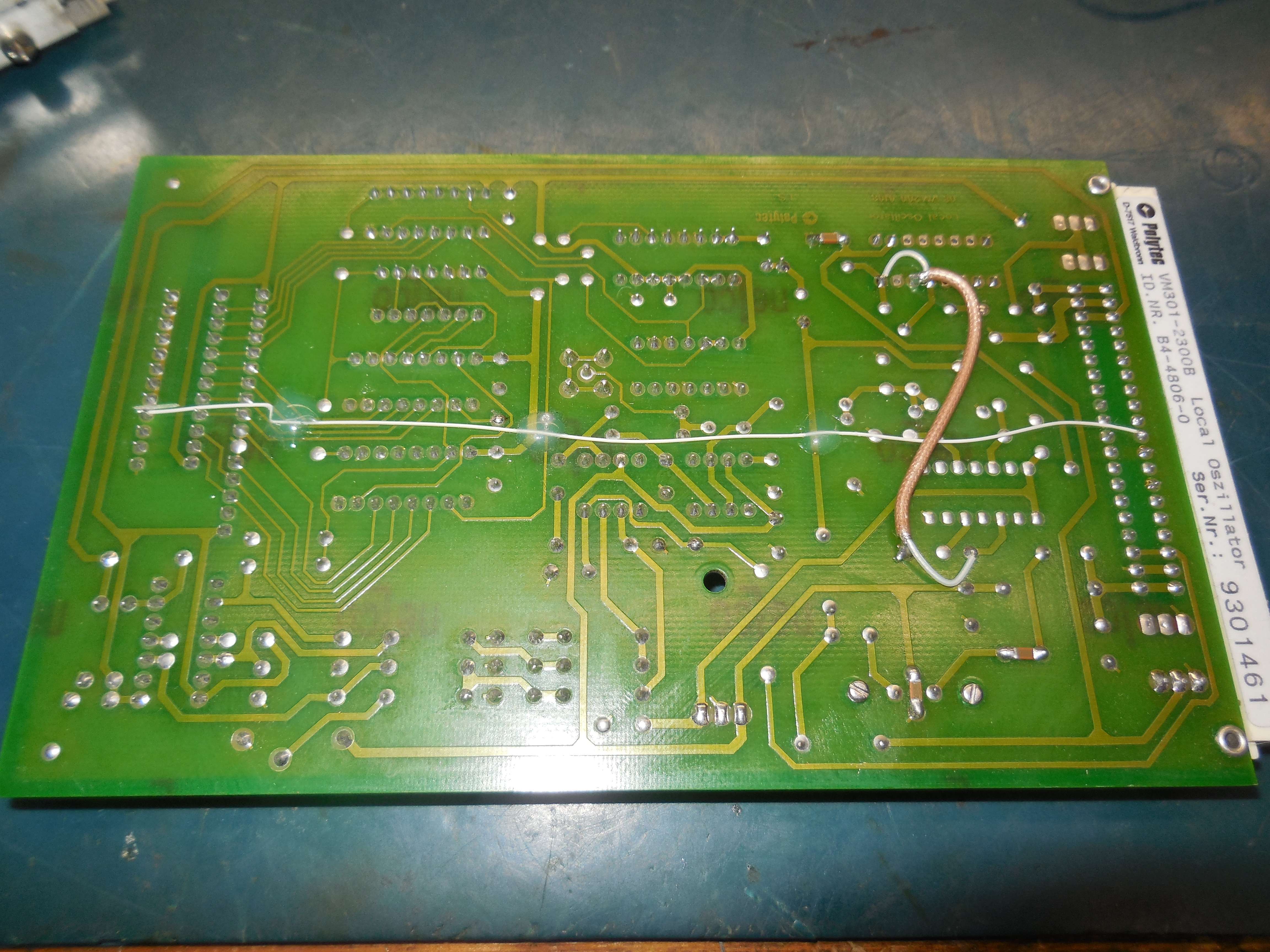
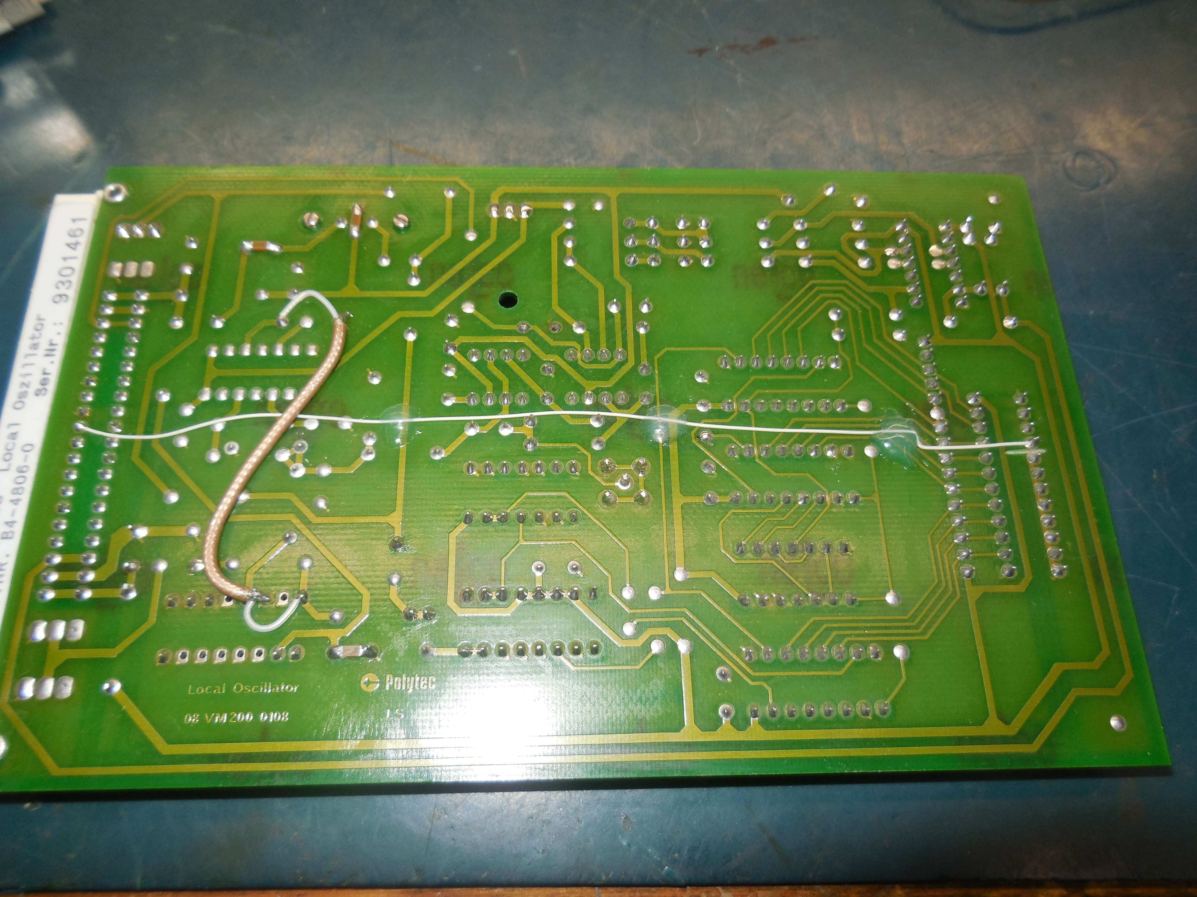
VM301-2300B Local Oscillator Board (30-60 MHz)

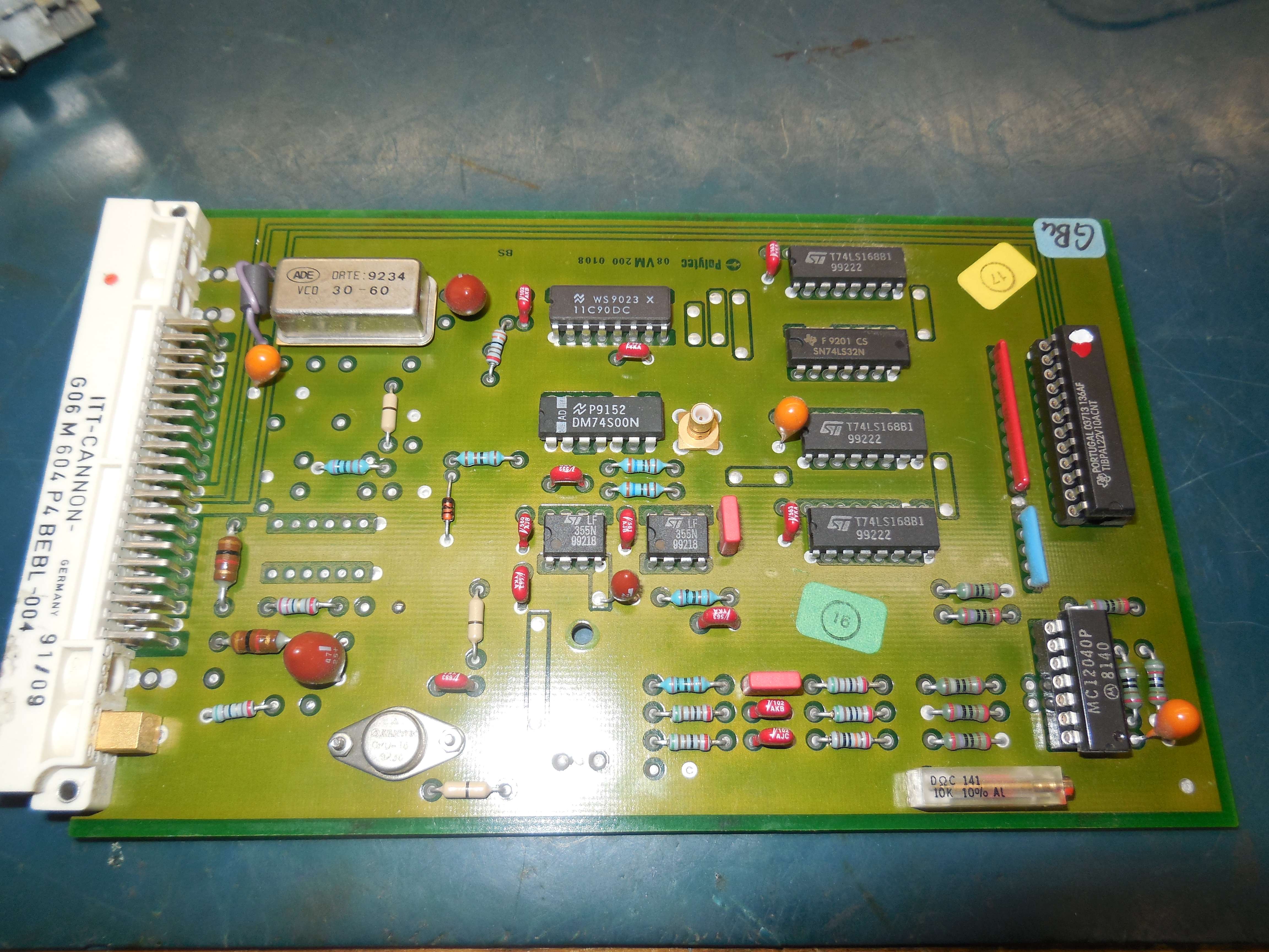
11C90, MC12040, LF355, Avantek GPD-464
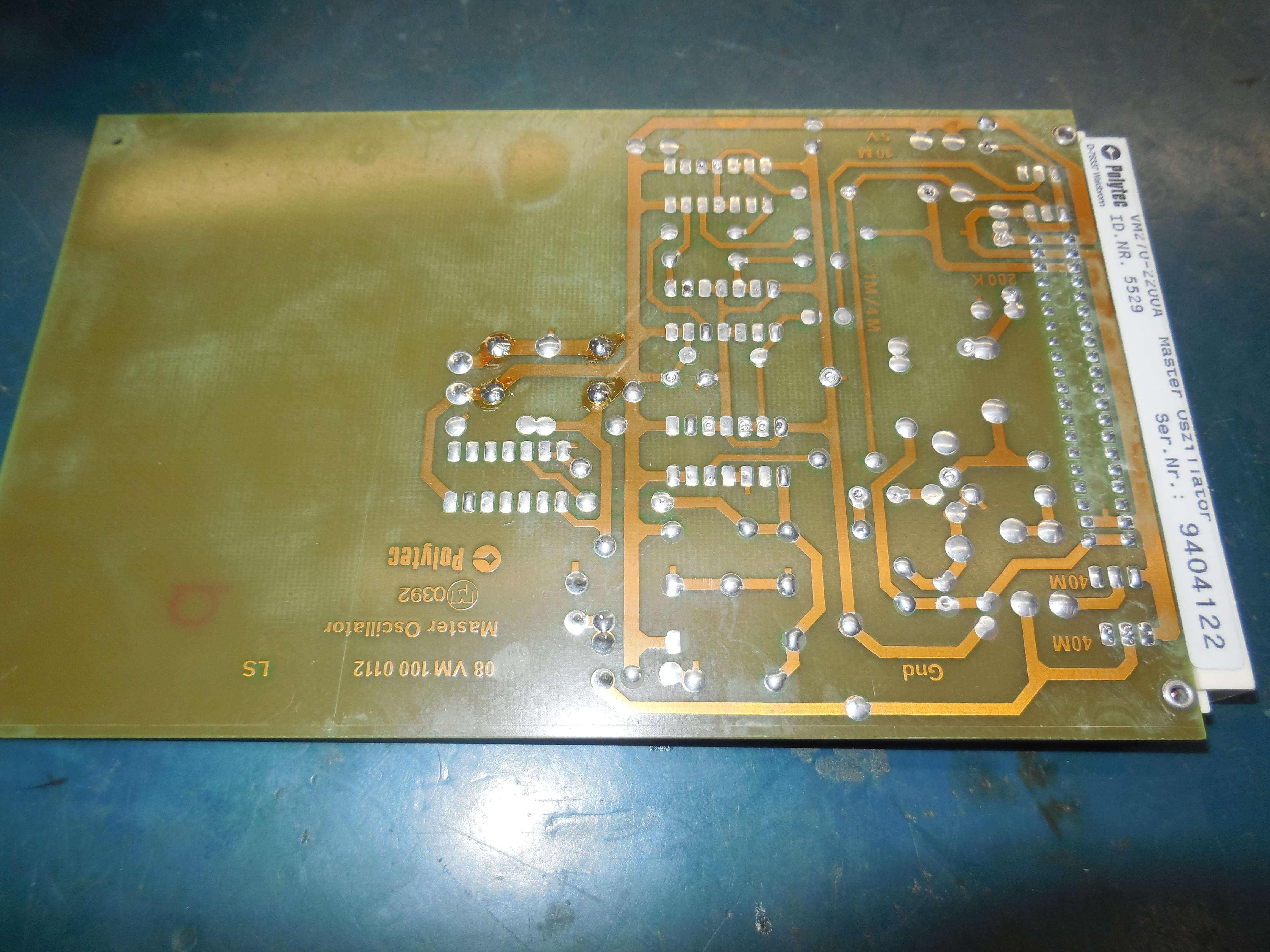
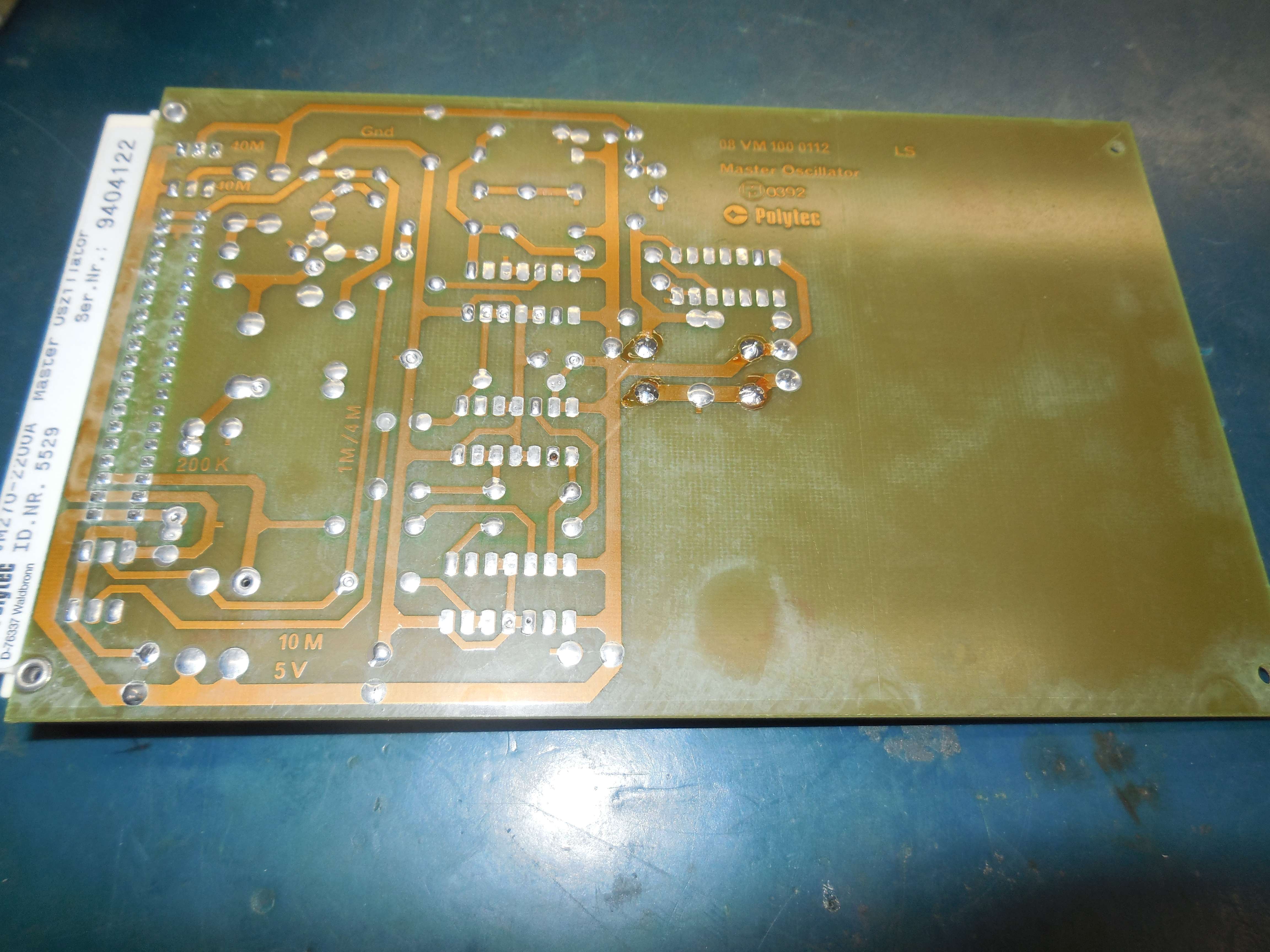
VM301-2200A Master Oscillator Board (80 MHz to Bragg AOM)
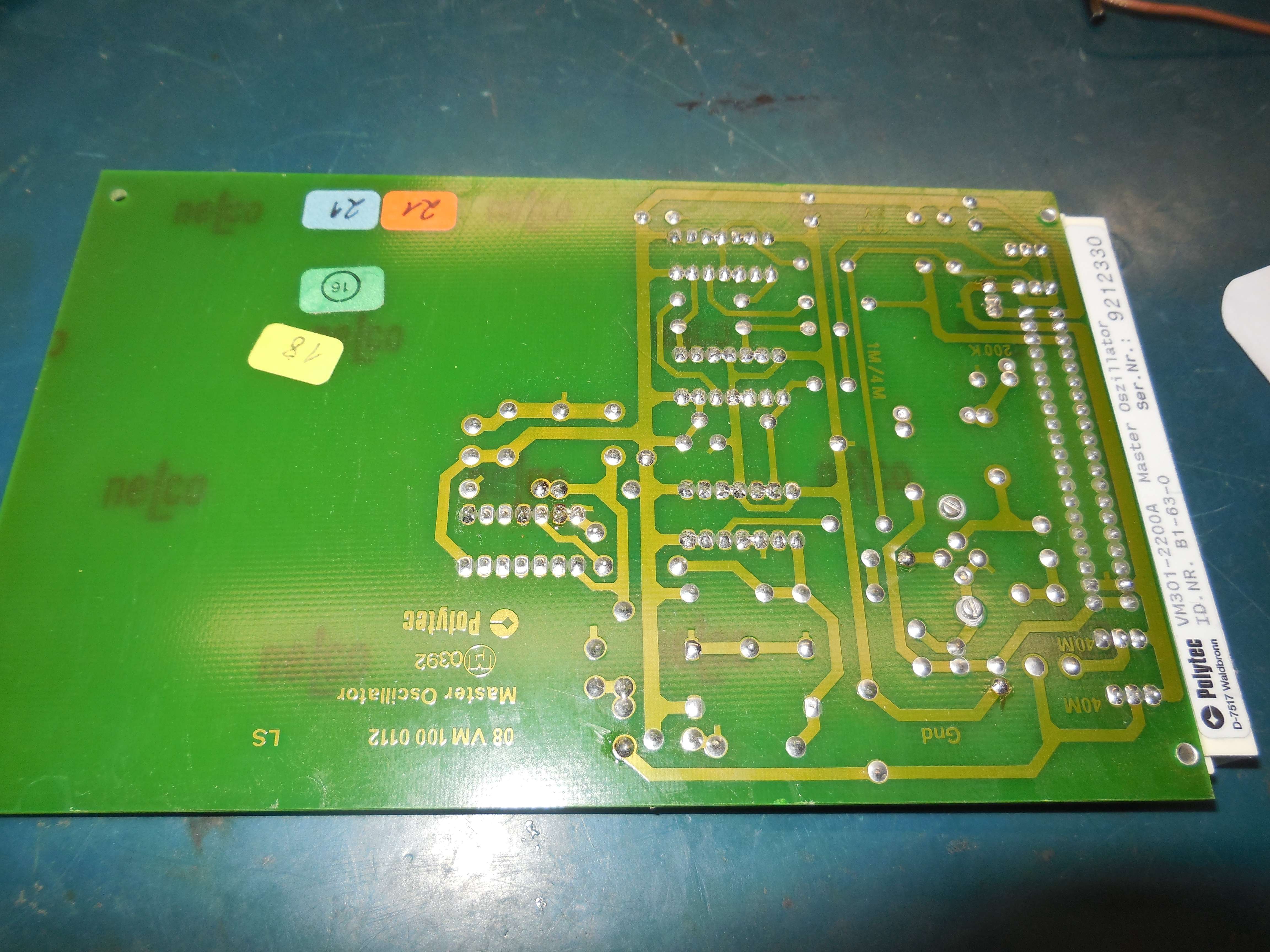
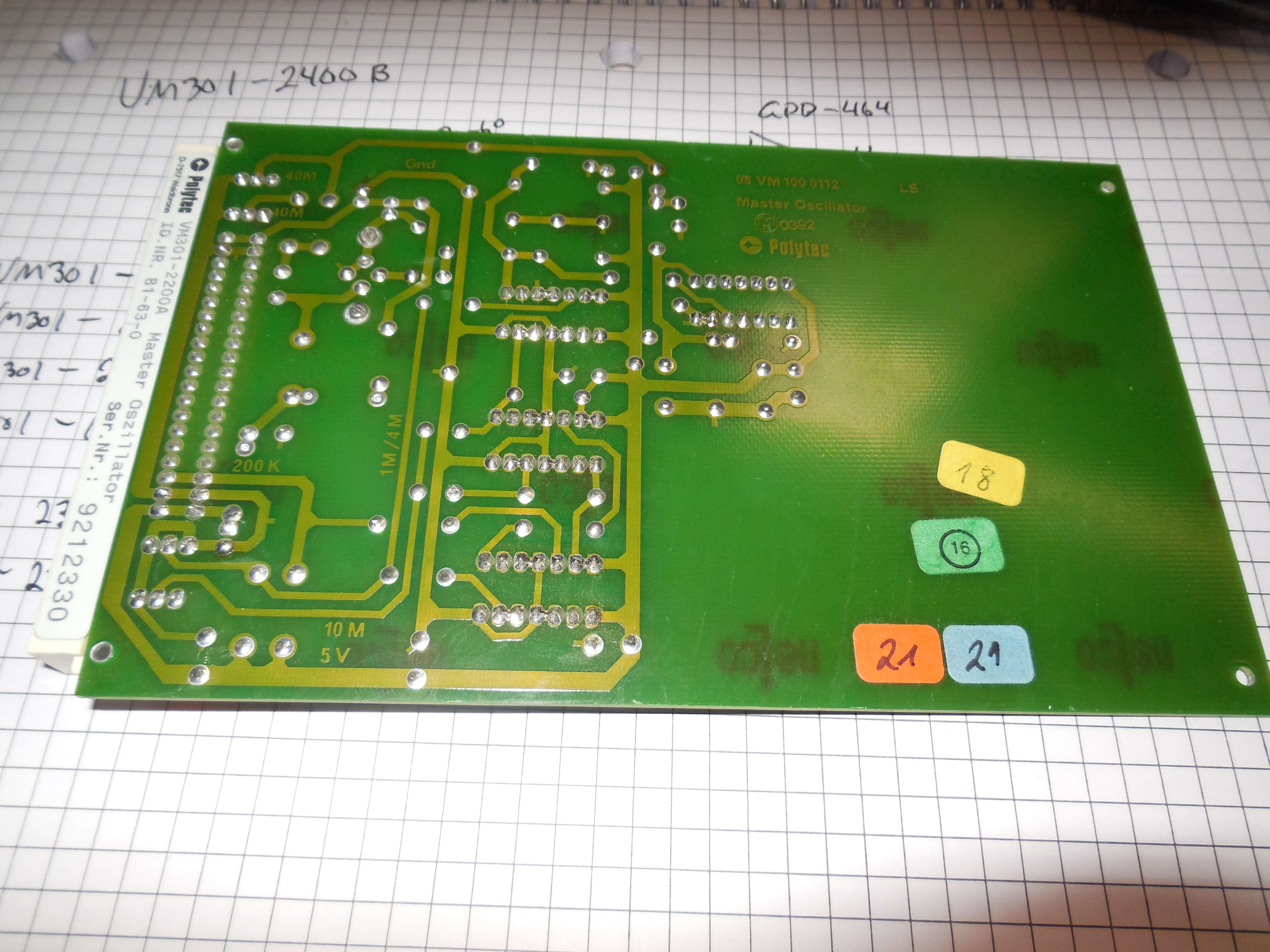
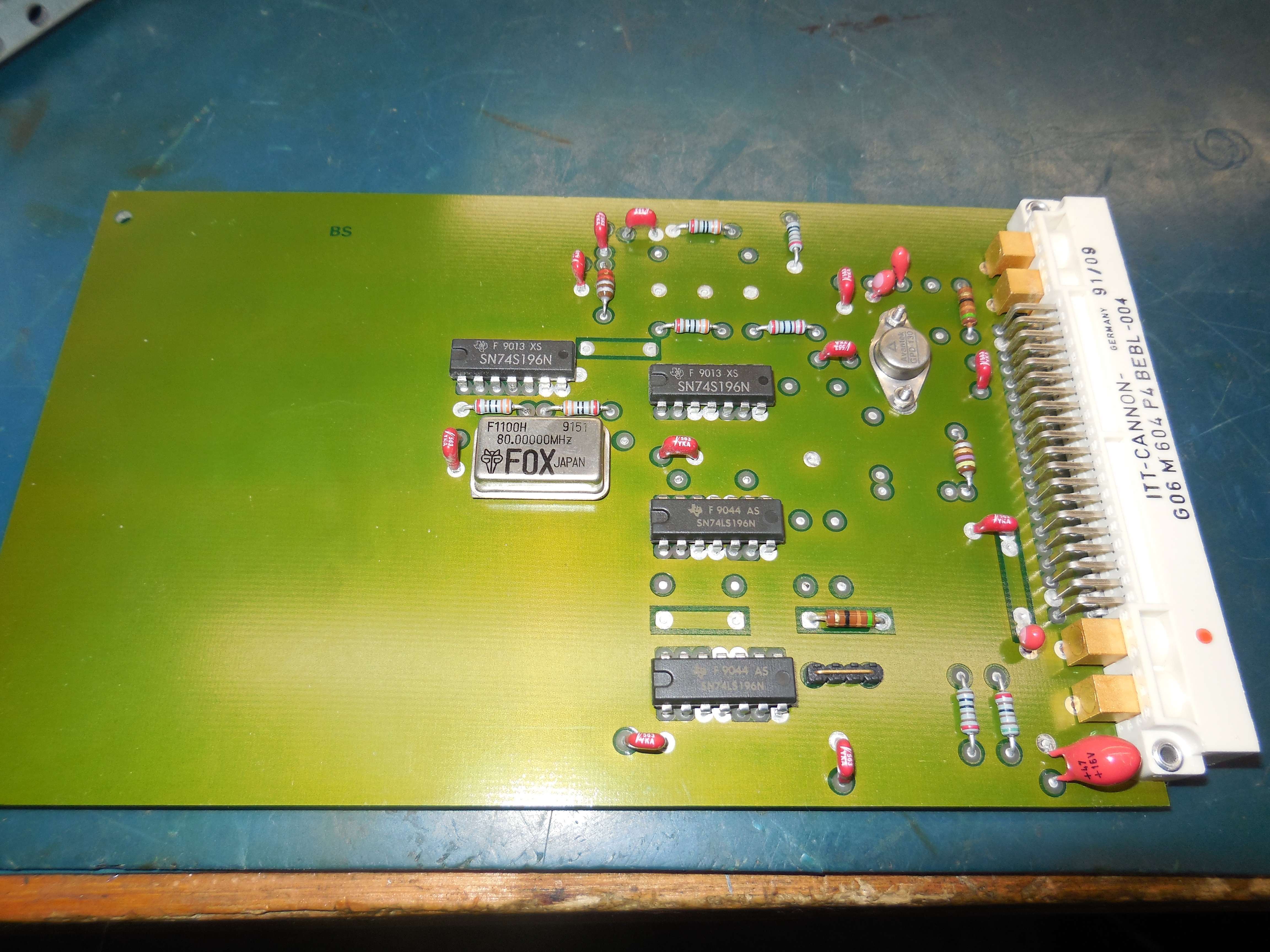
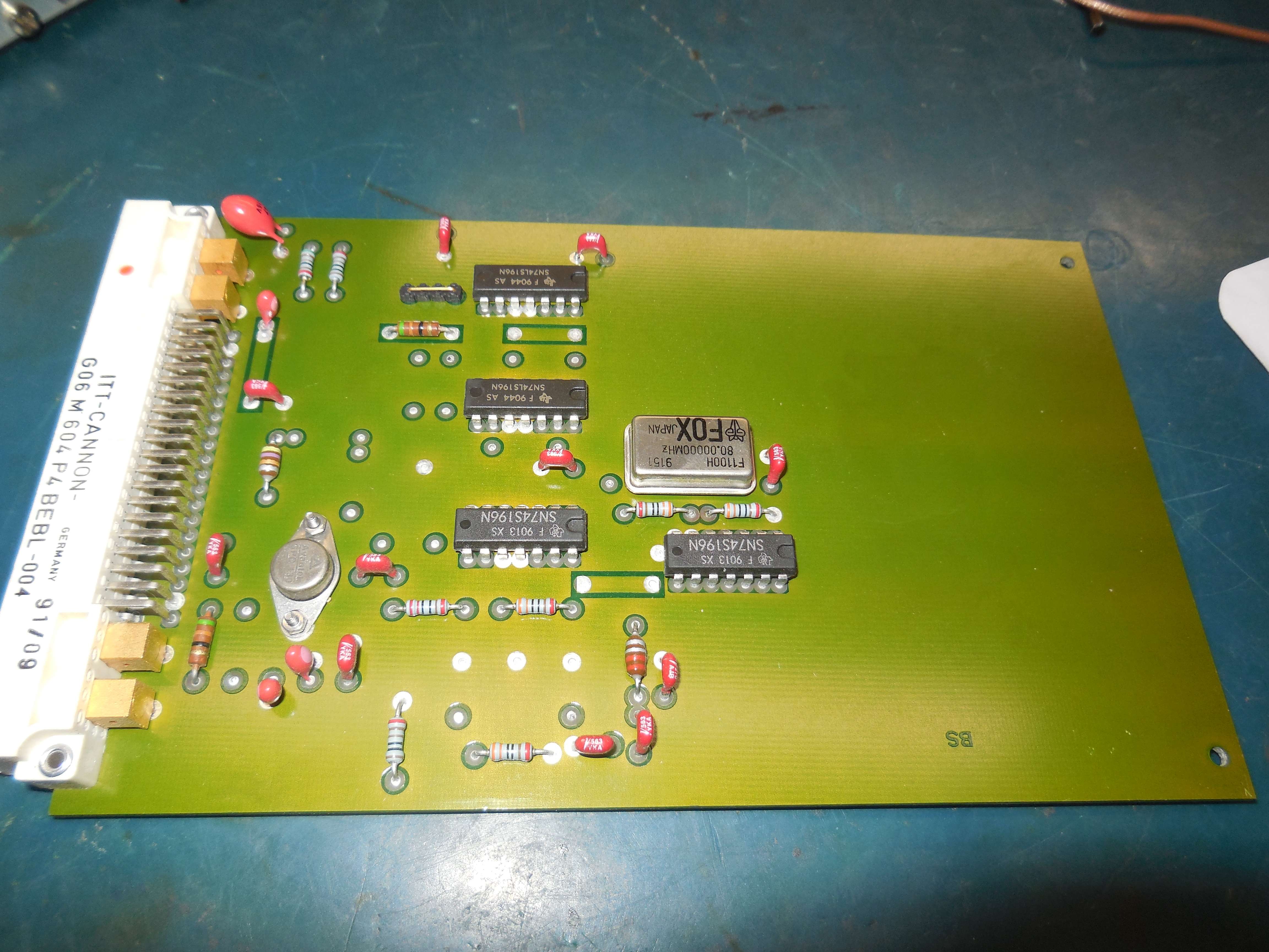
FOX F1100H 80 MHz clock oscillator, Avantek GPD-130, 74LS196
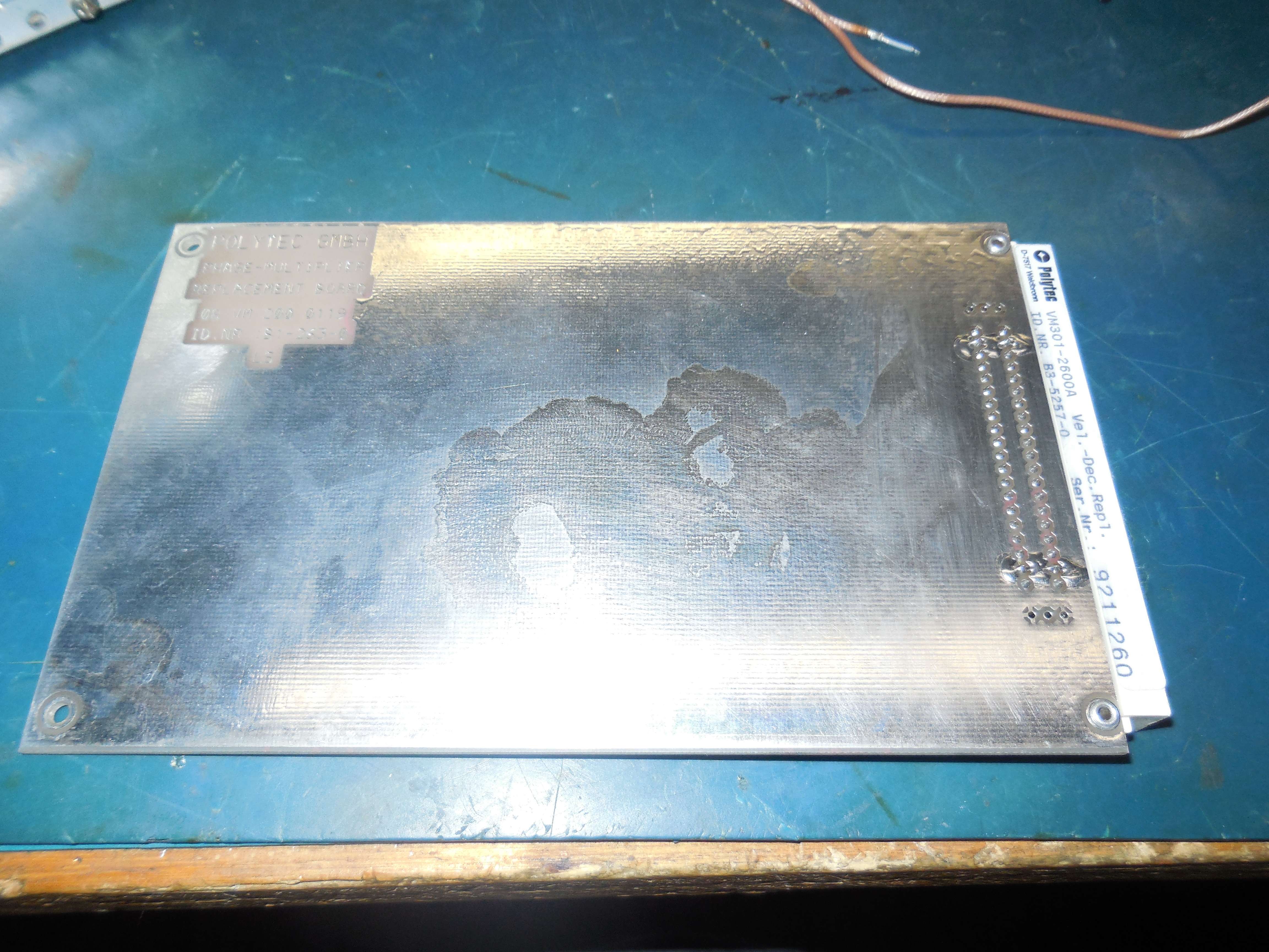
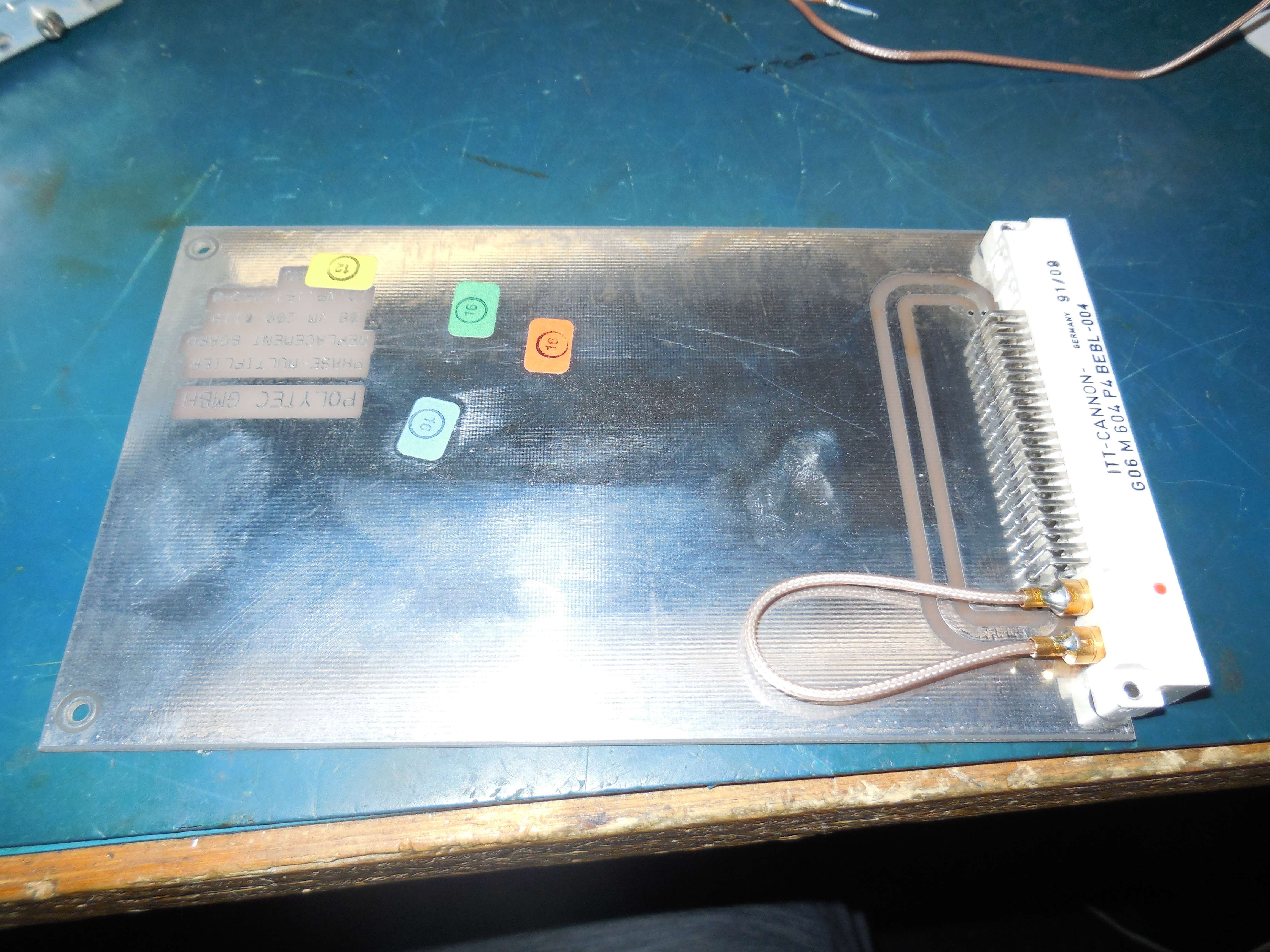
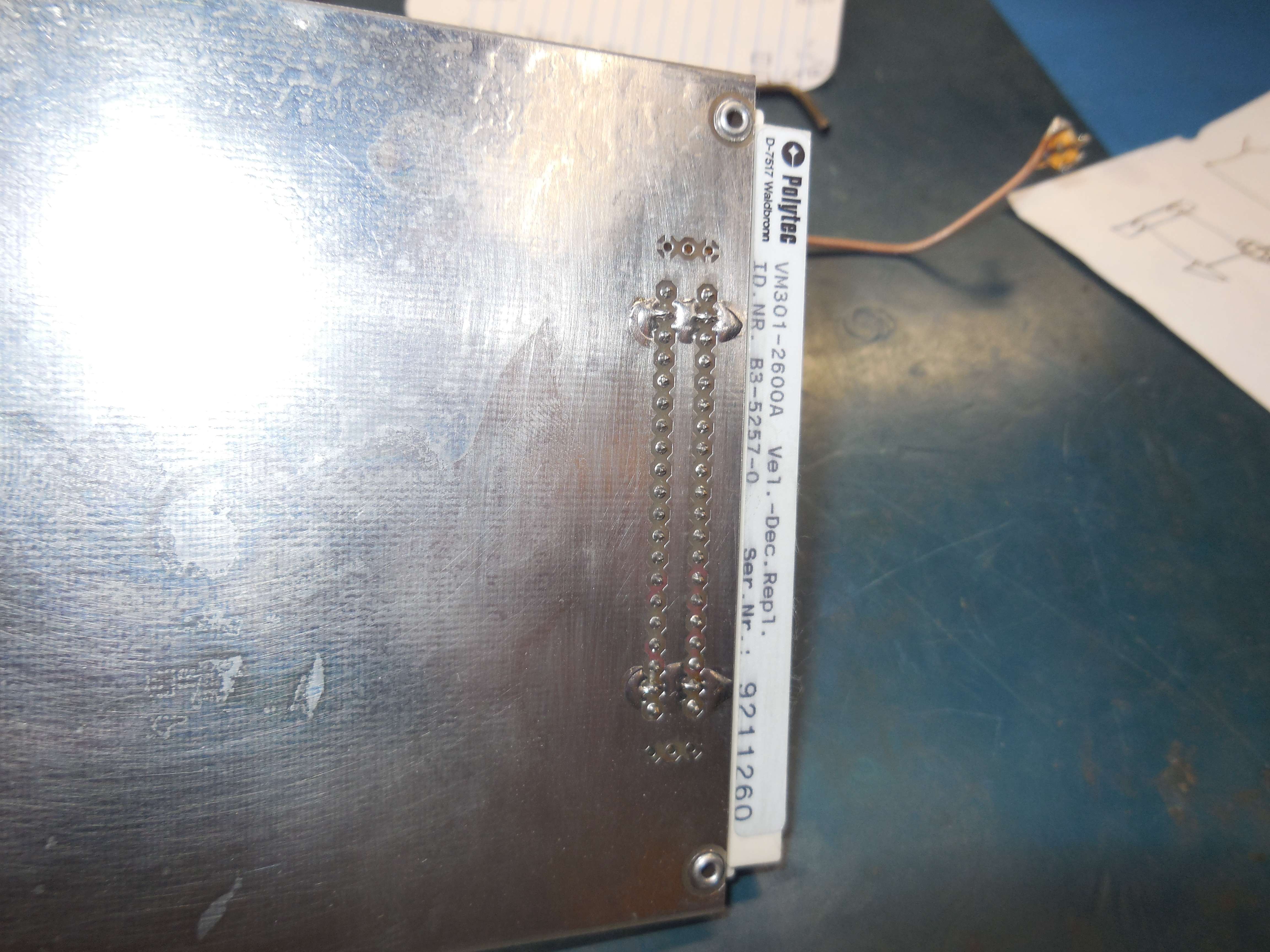
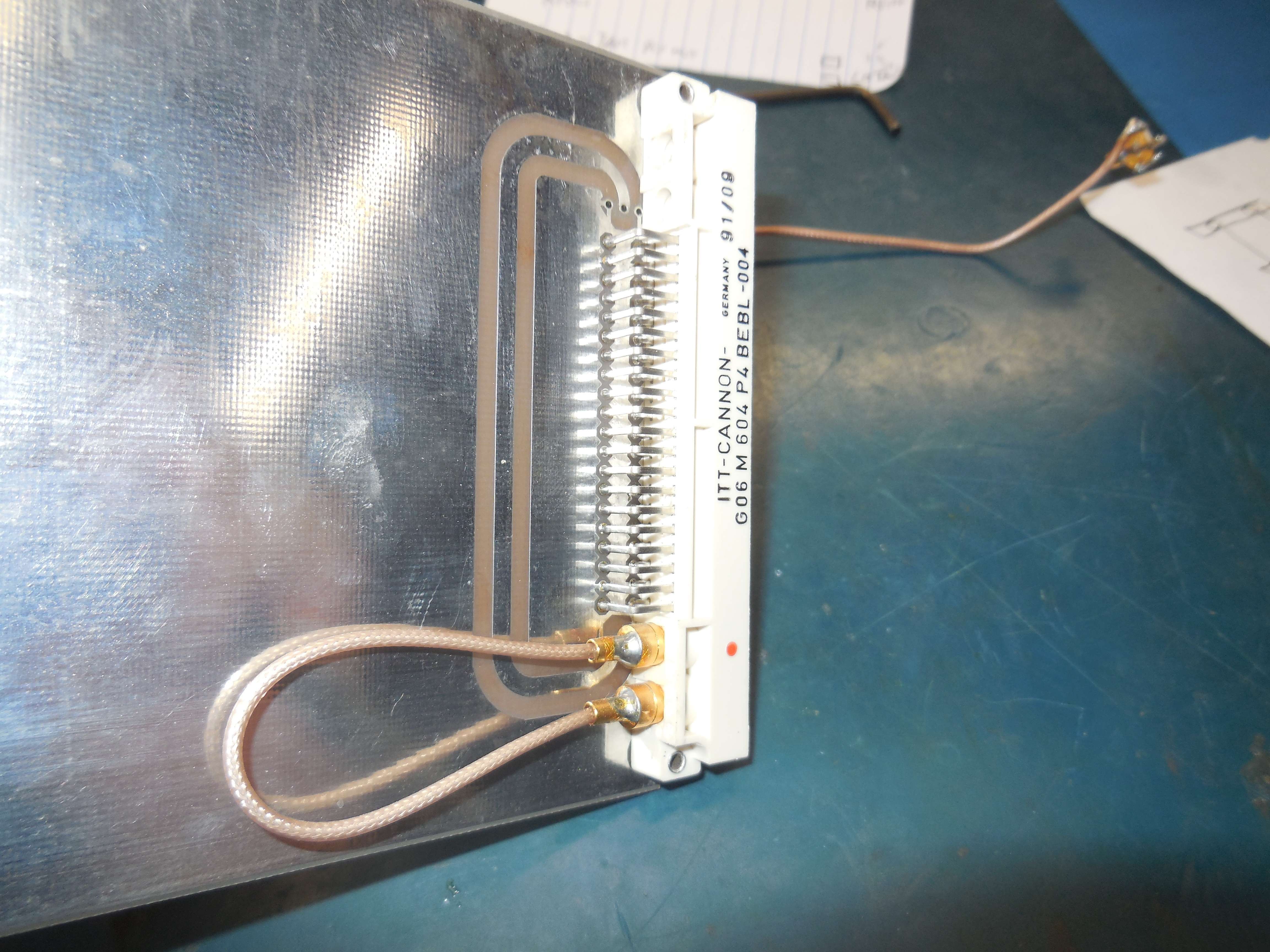
VM301-2600A Velocity Decoder Replacement Board (Phase Multiplier Replacement Board)
OFV-3000 Mainboard
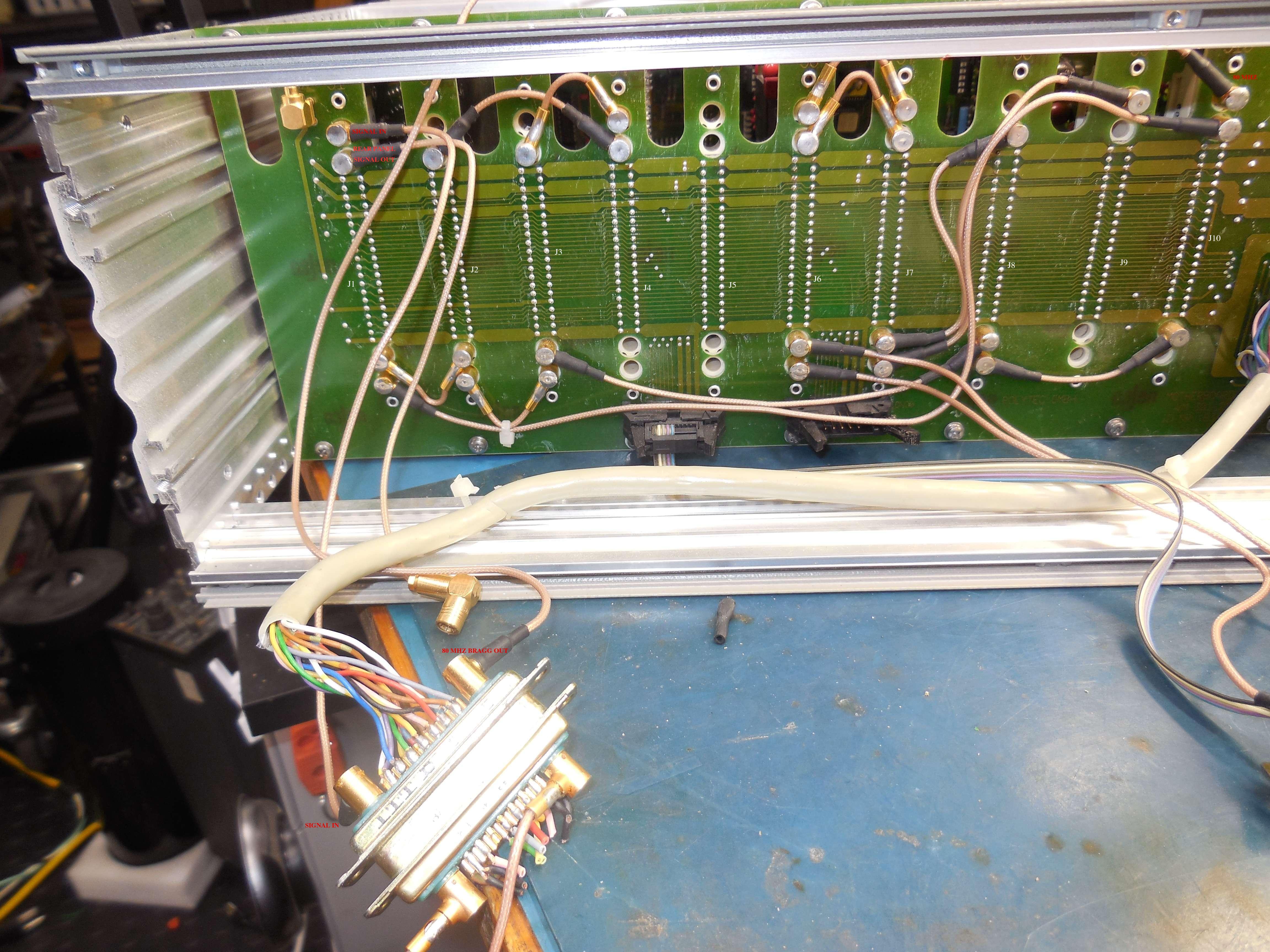
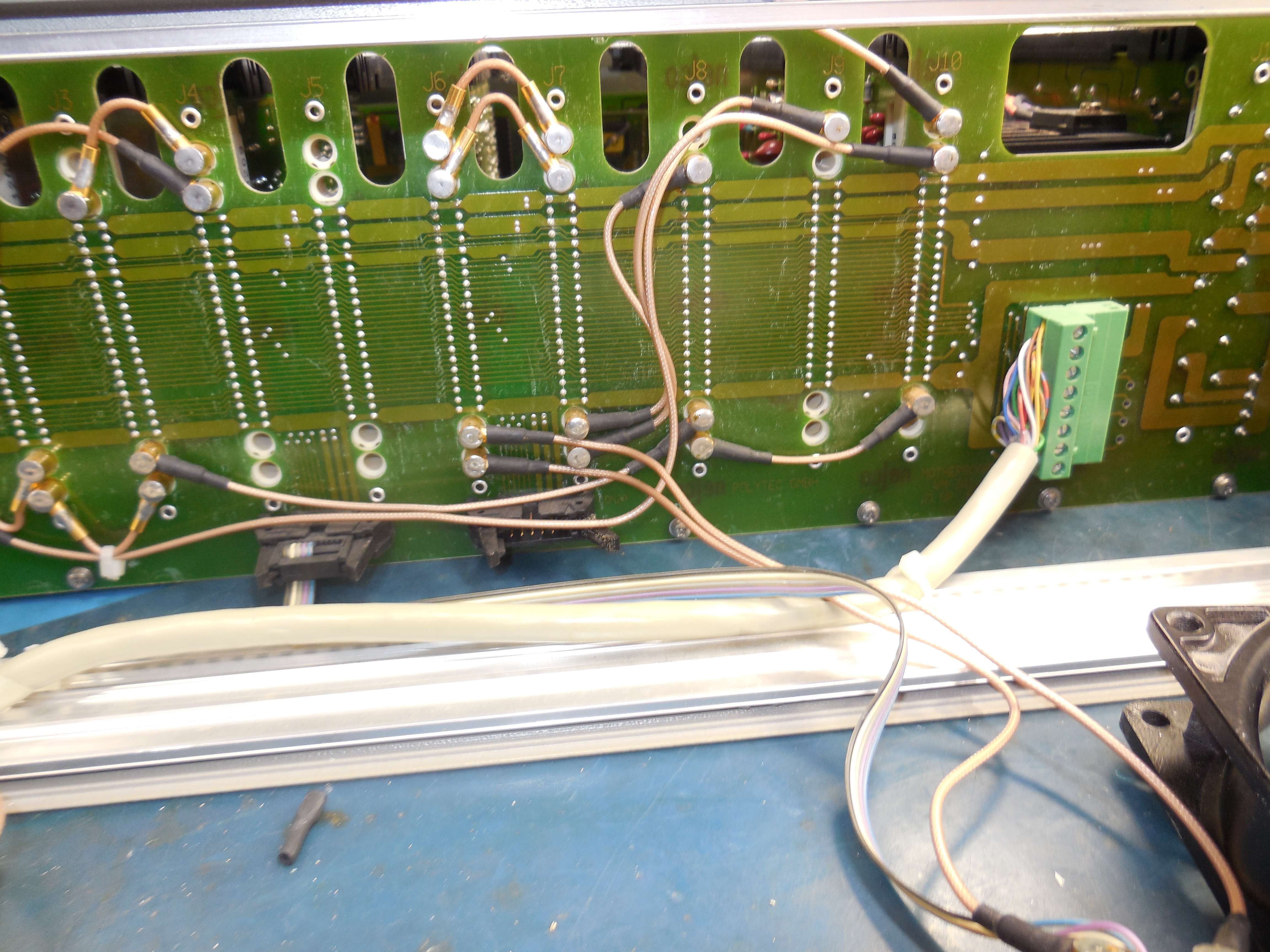
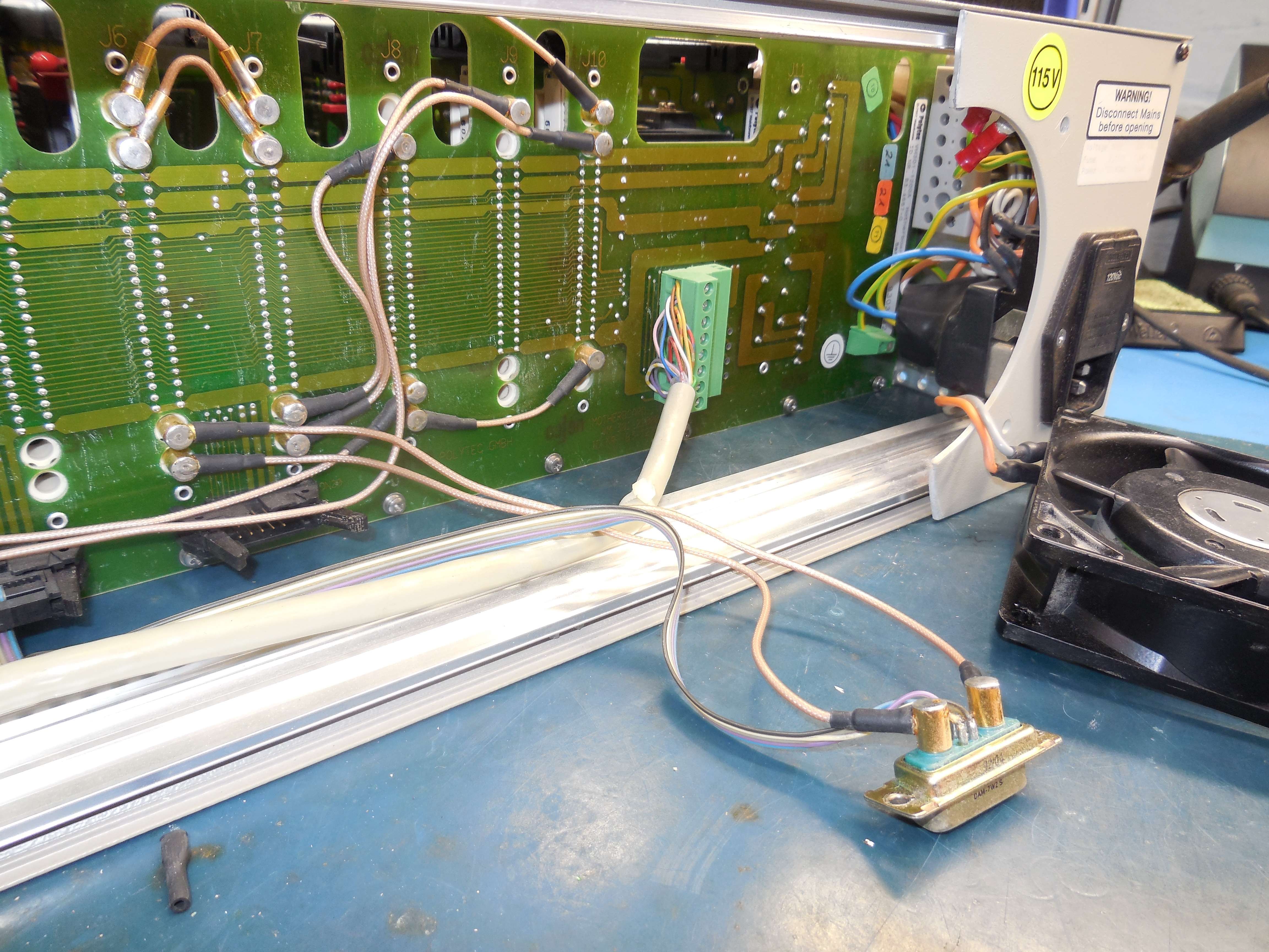
Rear-View: J1 is on the left. Front-View: J1 is on the right.
- J1: VM301-2400B Input Board
- J2: VM301-2600A Velocity Decoder Replacement Board (Pass-Through)
- J3: Empty
- J4: VM301-2400C Output Board
- J5: Empty
- J6: VM301-6000E PLL Velocity Board (w/ Fringe Counter Output) (OVD-01)
- J7: Empty
- J8: Empty
- J9: VM301-2300B Local Oscillator Board (30-60 MHz)
- J10: VM301-2200A Master Oscillator Board (80 MHz to Bragg AOM)
Configuration: Velocity Decoder 5 HL Ranges Displacement Decoder 0 Ranges Remote Focus Control Installed IEEE Bus Interface Installed |
I don't think this particular OFV-3000 was setup to measure displacement, but I don't know...
OFV-2810 Dual HF Vibrometer
Dual-output vibrometer with a fixed (?) velocity resolution of 125 mm/s/V.
Front-Panel Key Switch (Power) 51-236.025D "311" above keyhole Front Pin 3: Green Rear Pin 3: Yellow Front Pin 4: Brown Rear Pin 4: White |
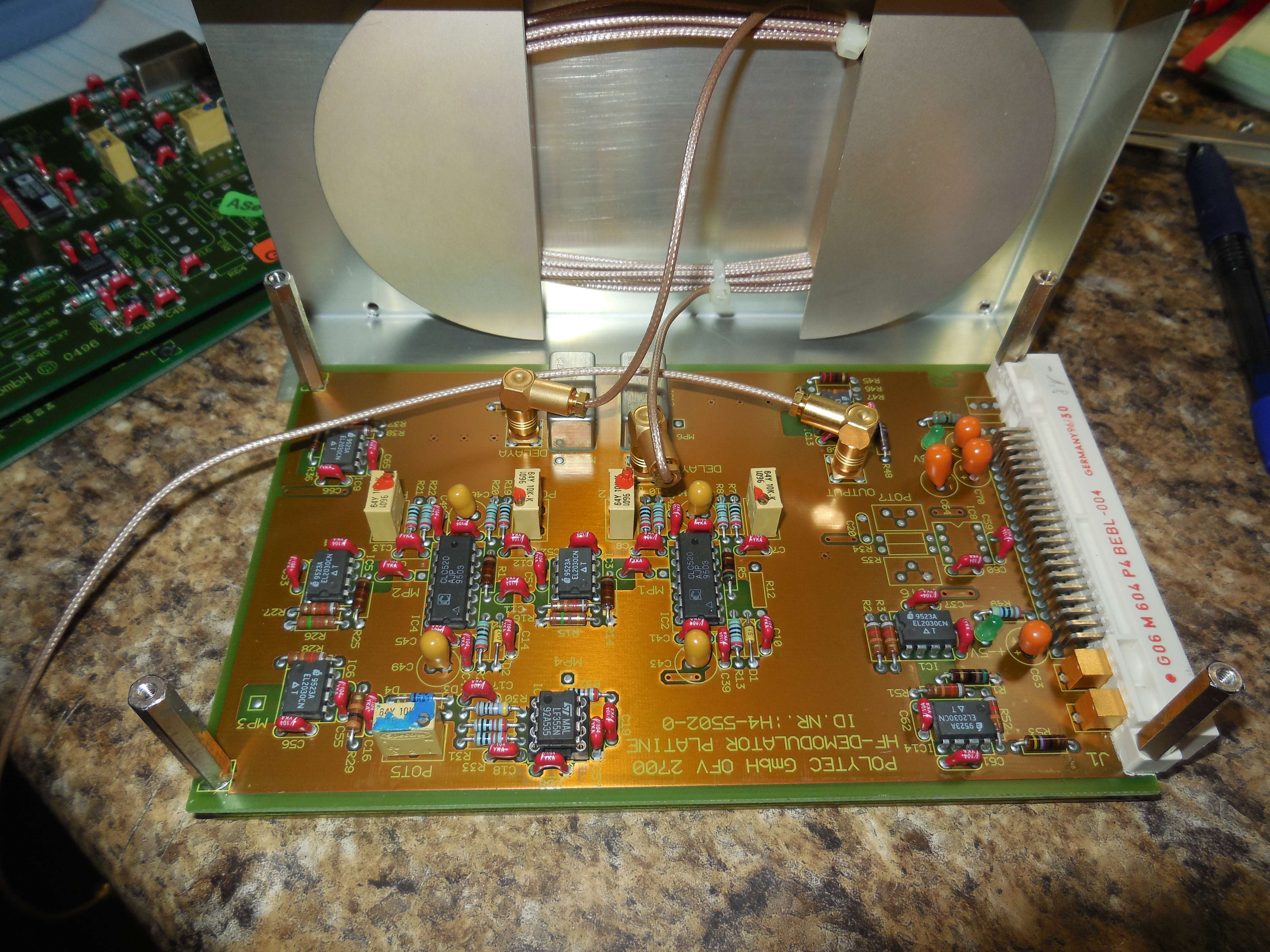
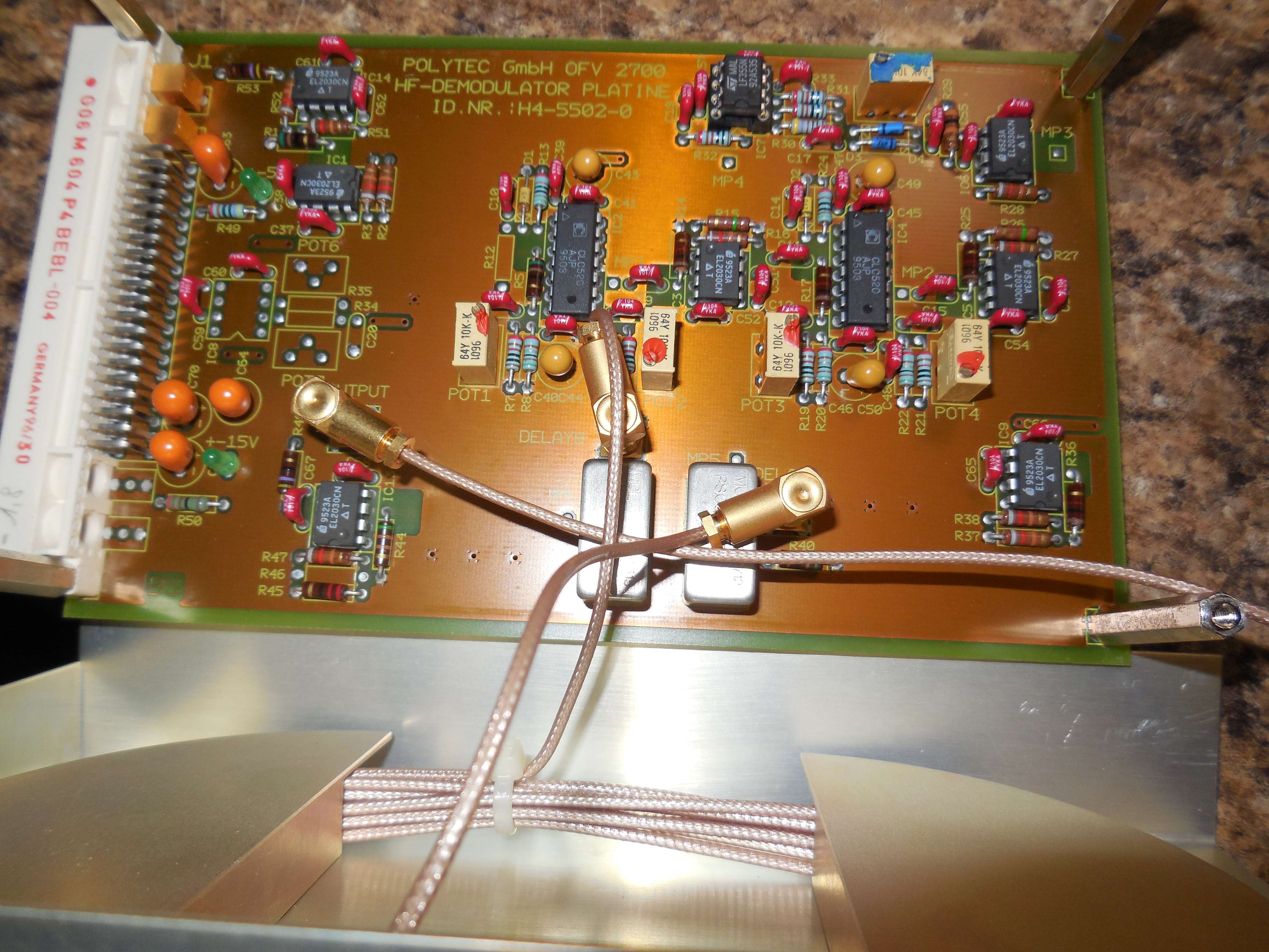
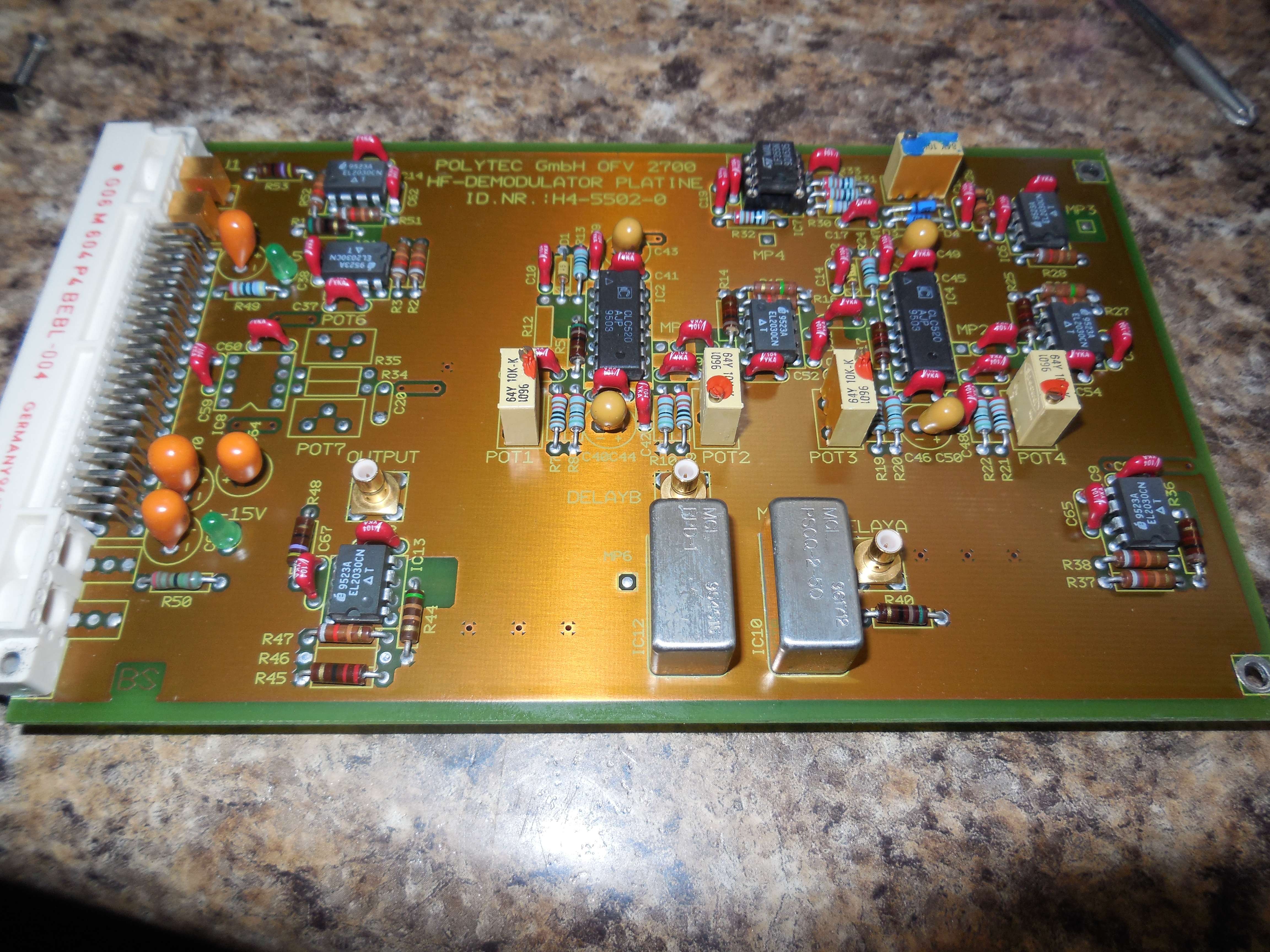
VM270-6200A HF Demodulator (Input)
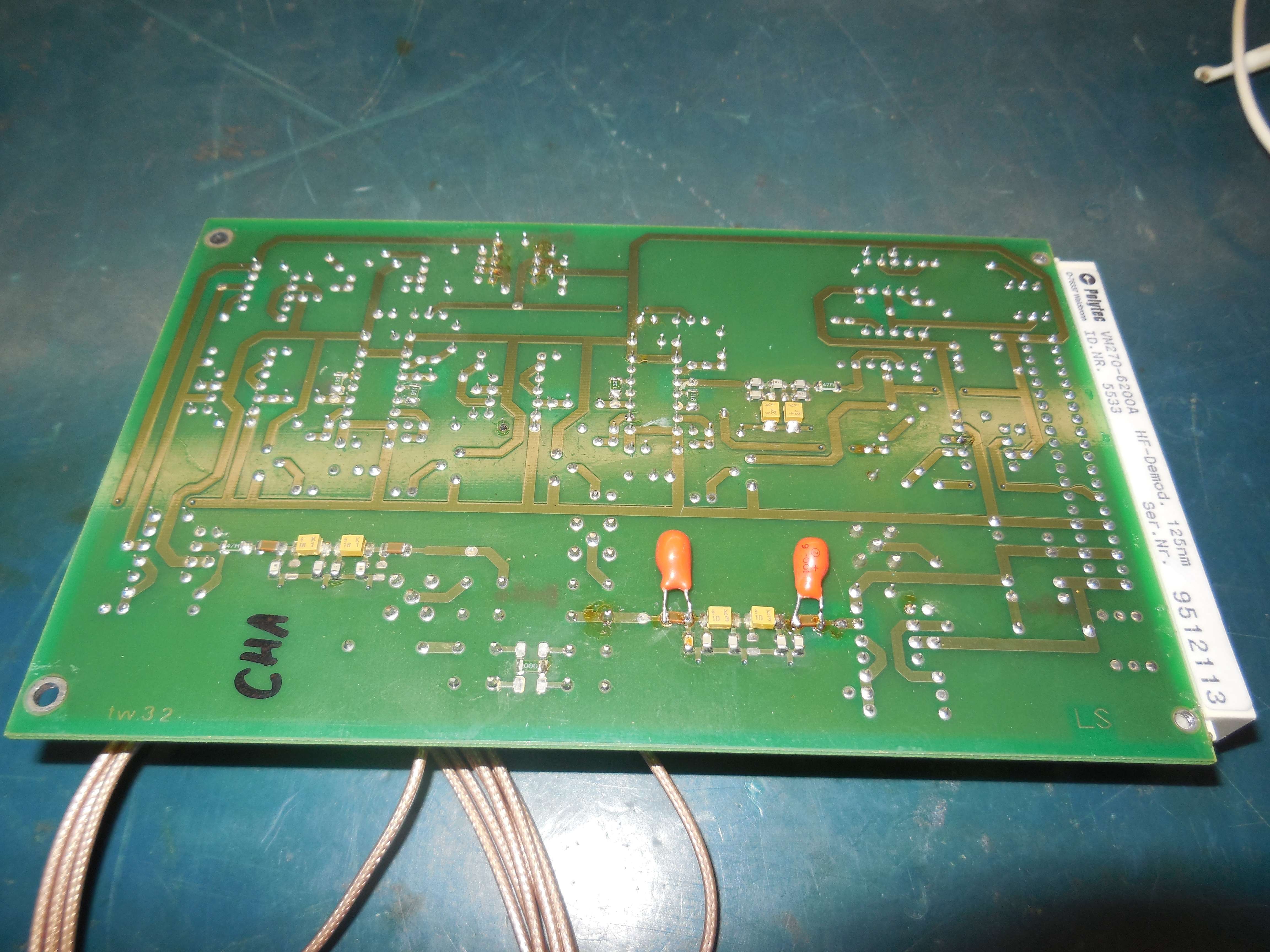
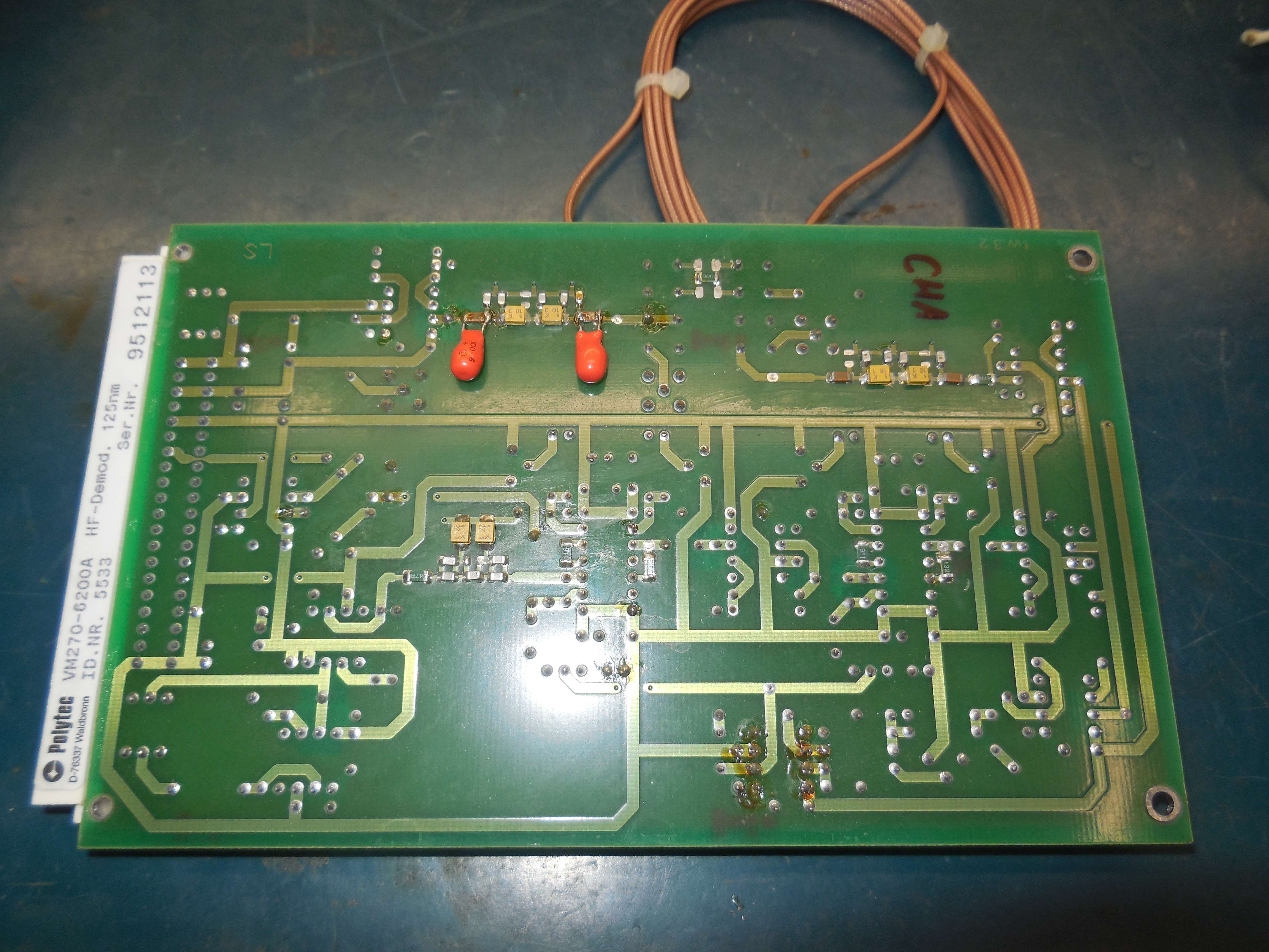
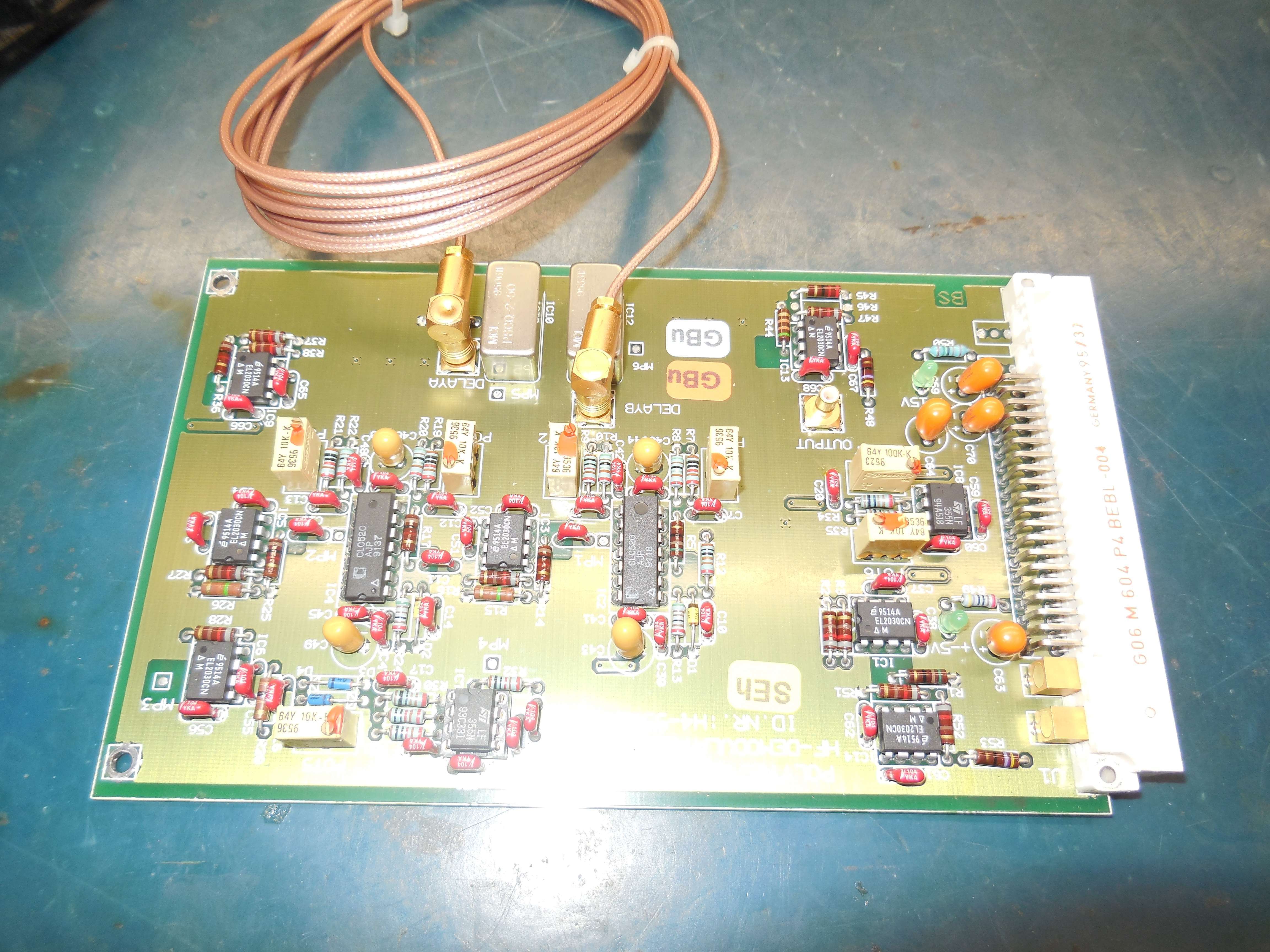
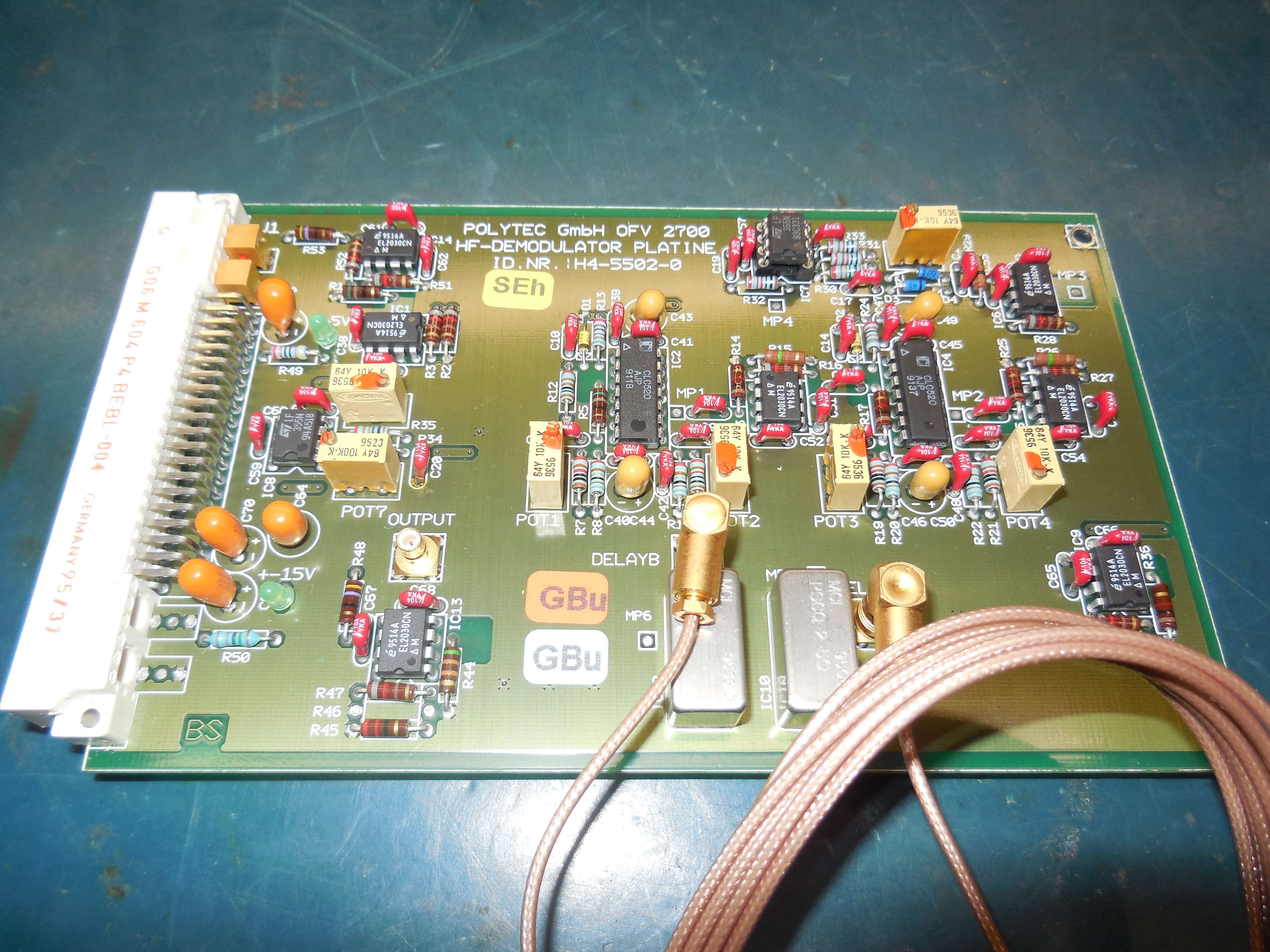
Frequency discriminator (frequency-to-voltage) via a coaxial delay line and 90° phase shift into the MCL RPD-1.
EL2030, CLC520, LF355, MCL RPD-1, MCL PSCQ-2-50.
Both channels, "Channel A" and "Channel B" use the same hardware.
CLC520, EL2030, MCL PSCQ-2-50, MCL RPD-1
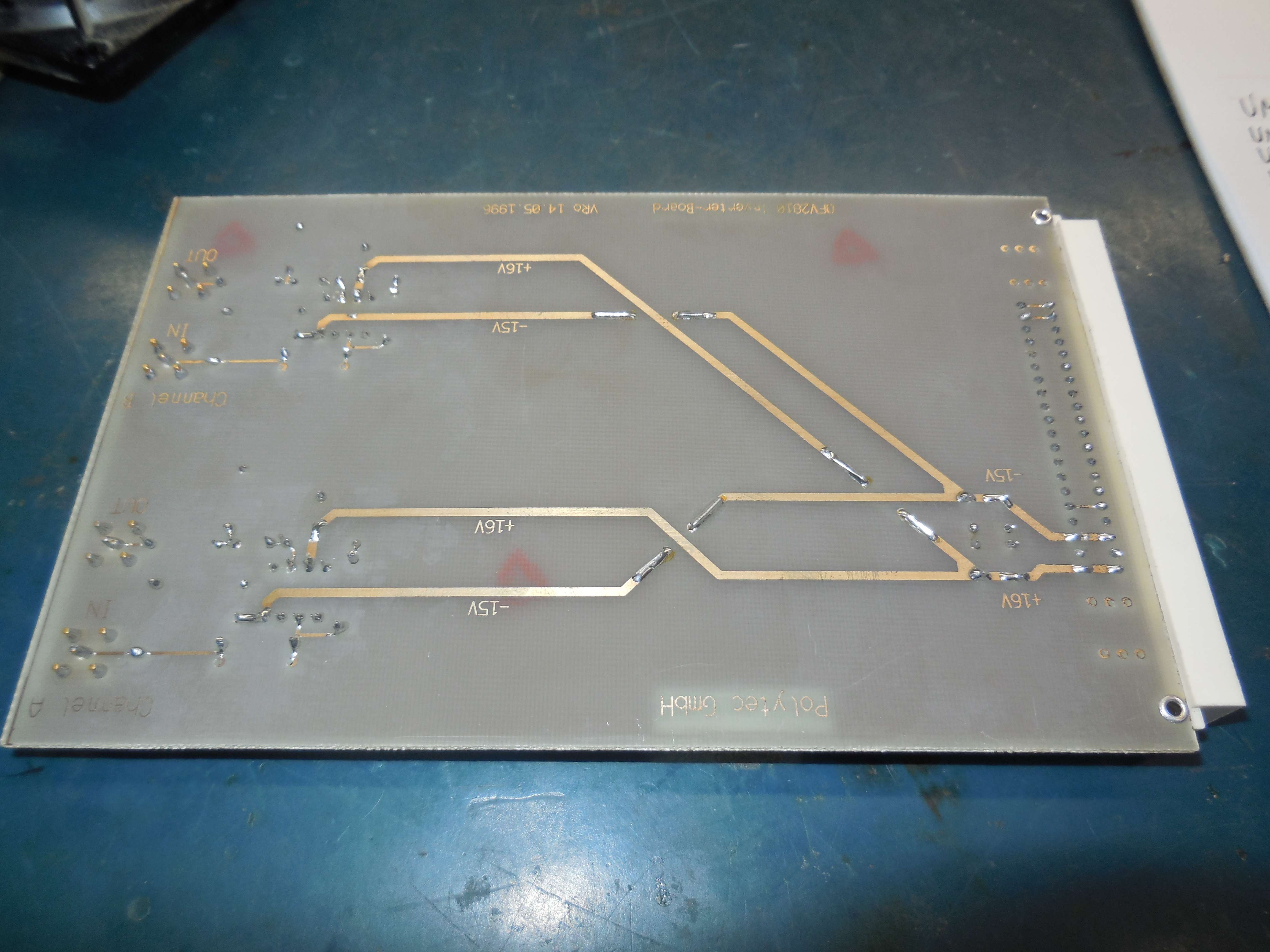
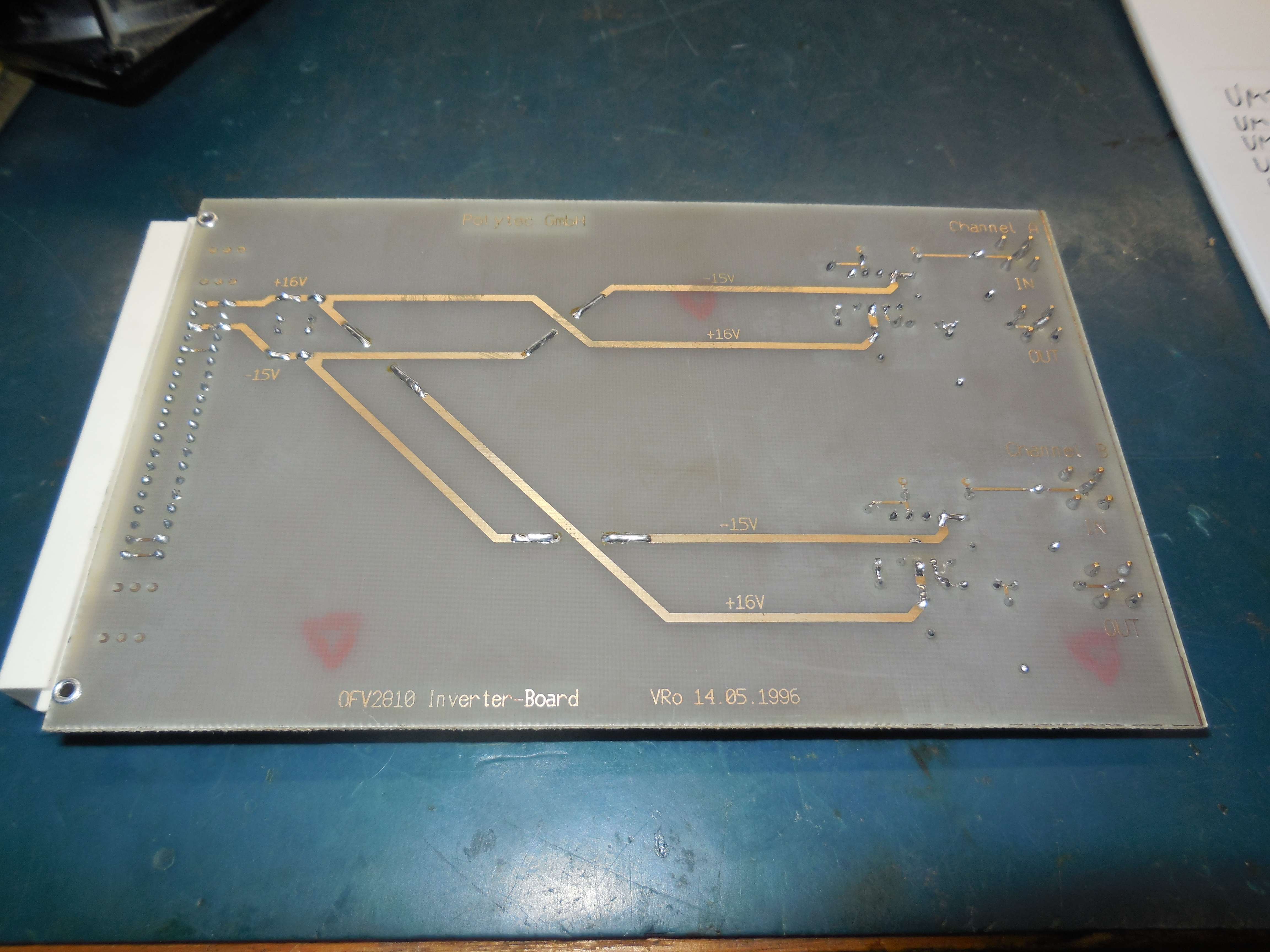
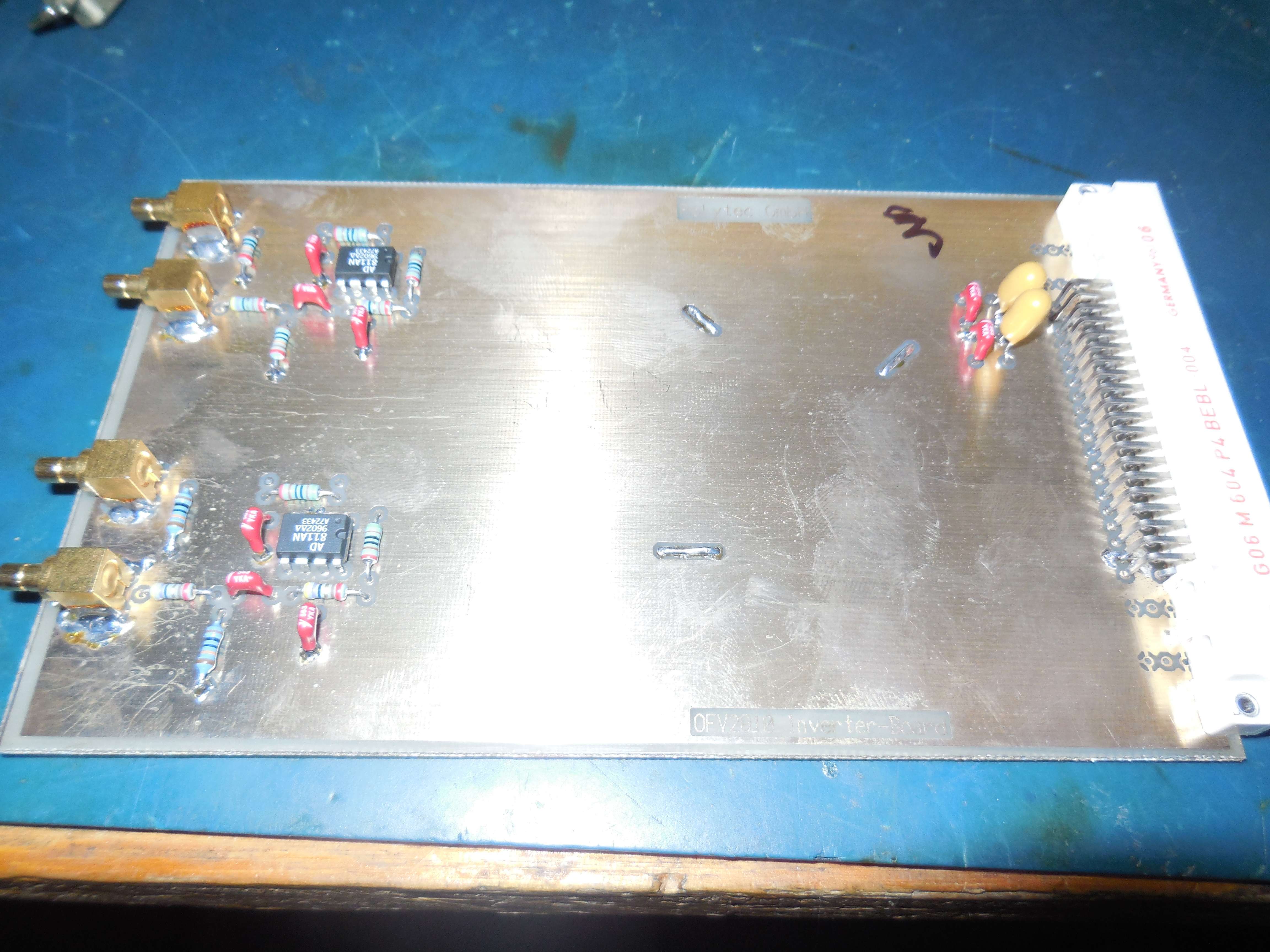
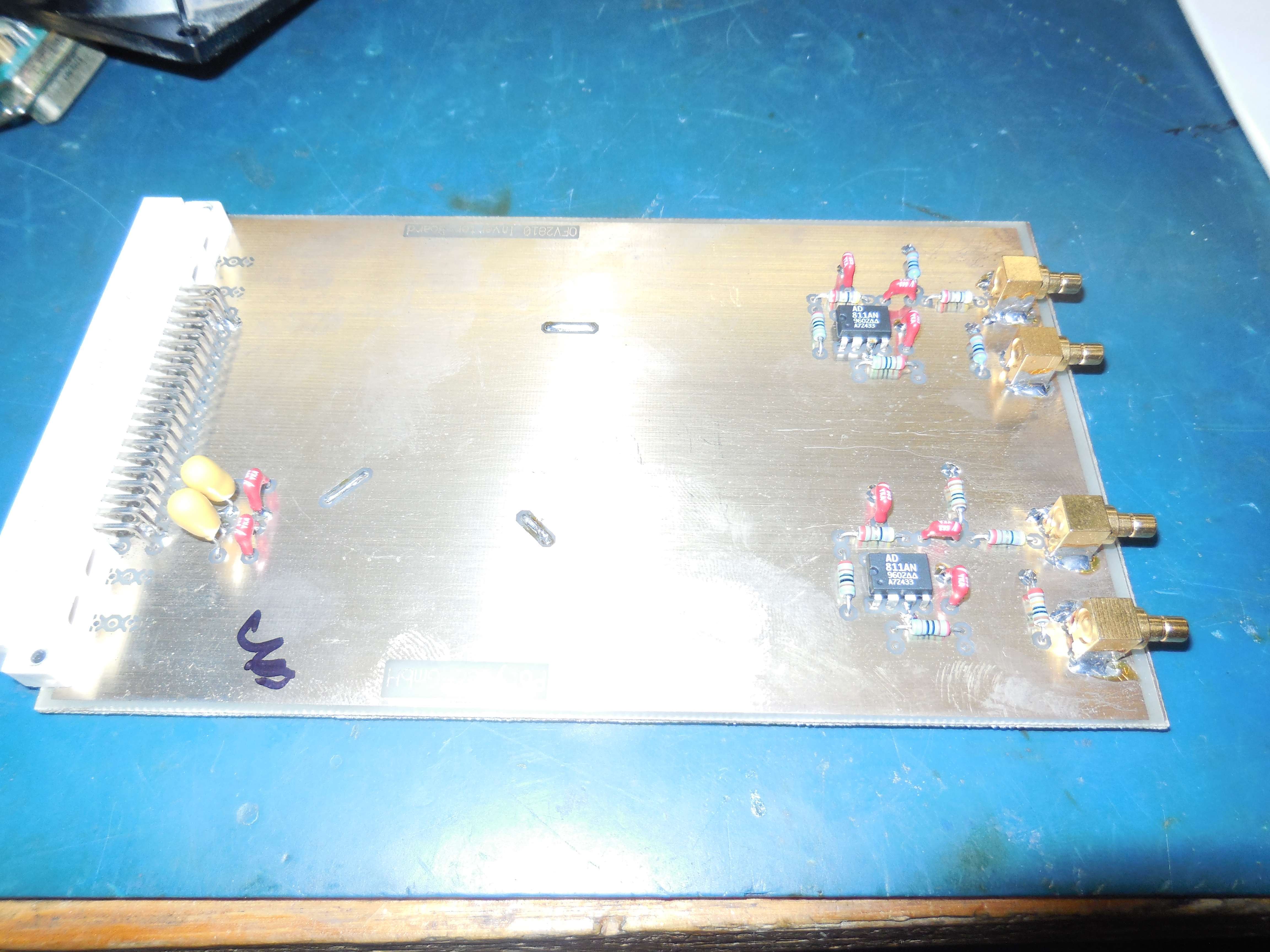
OFV-2810 Inverter Board
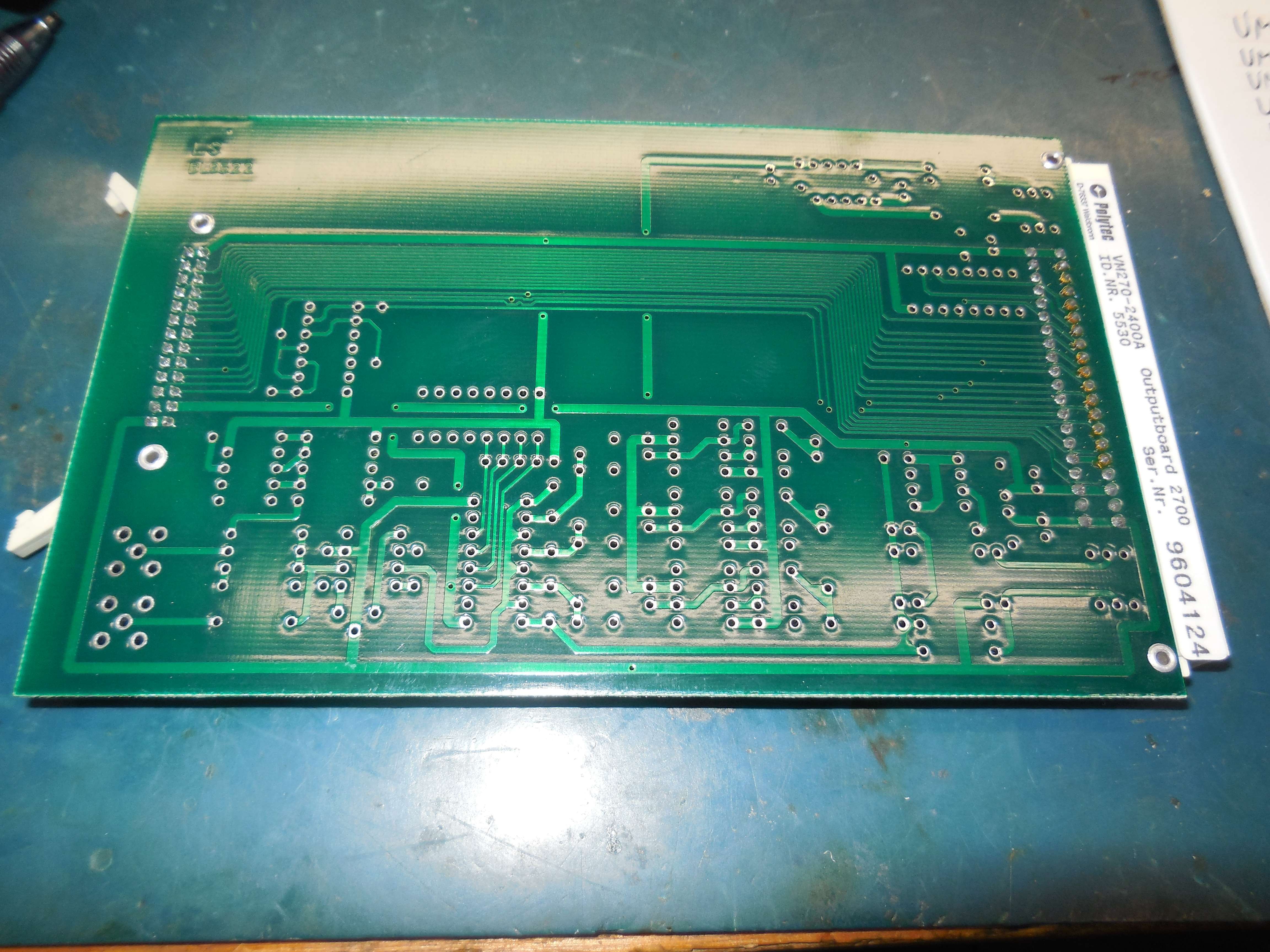
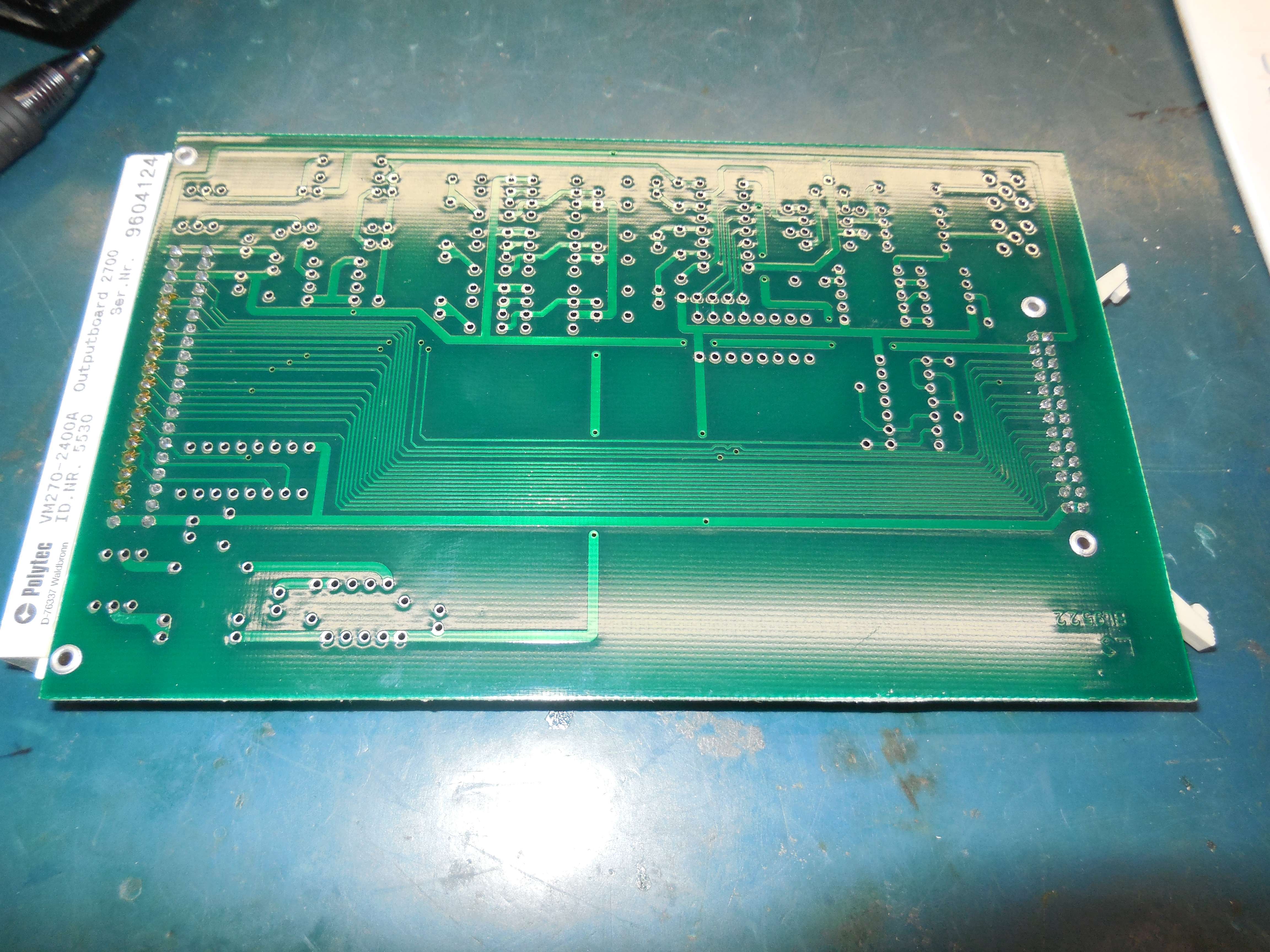
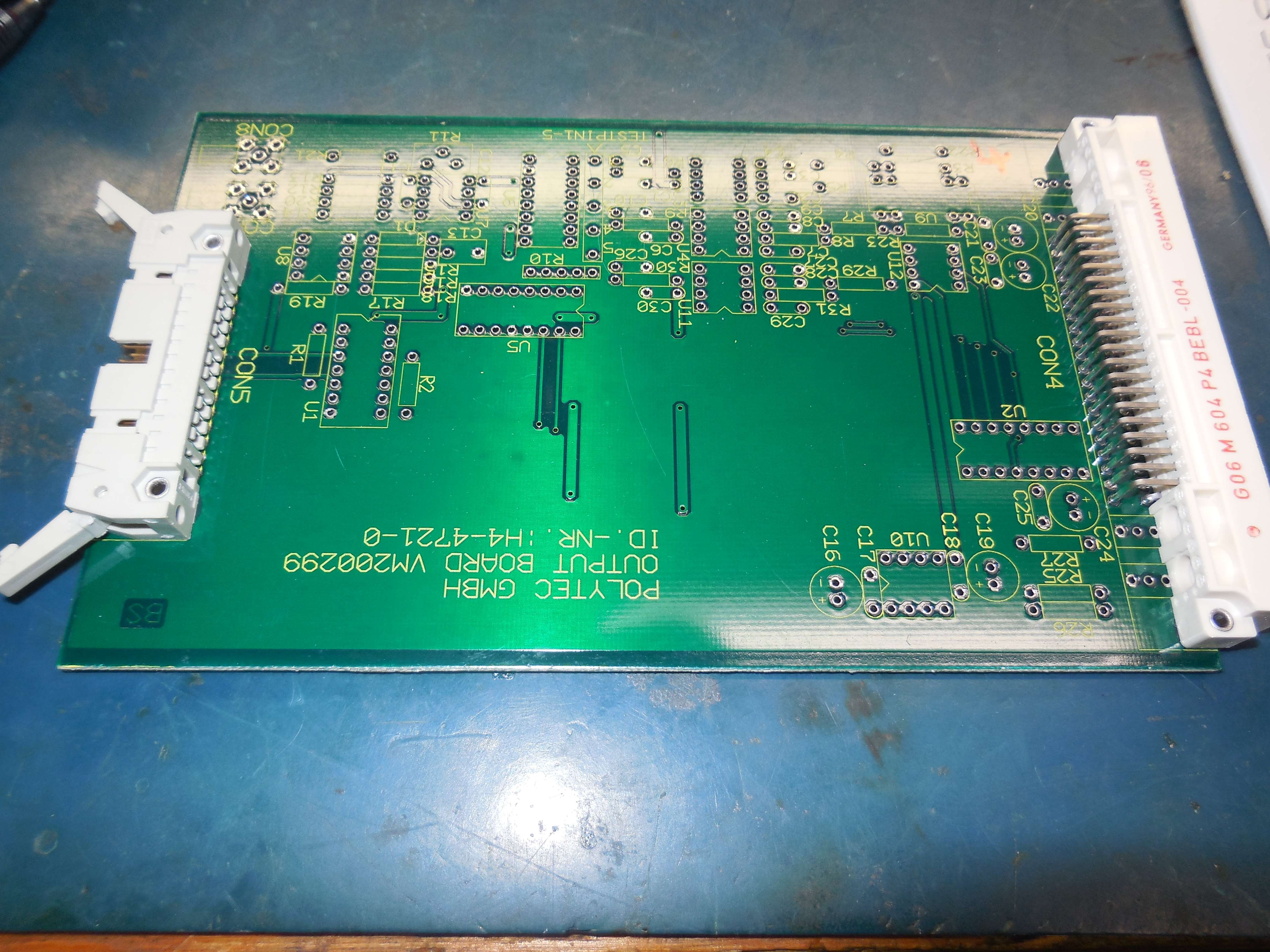
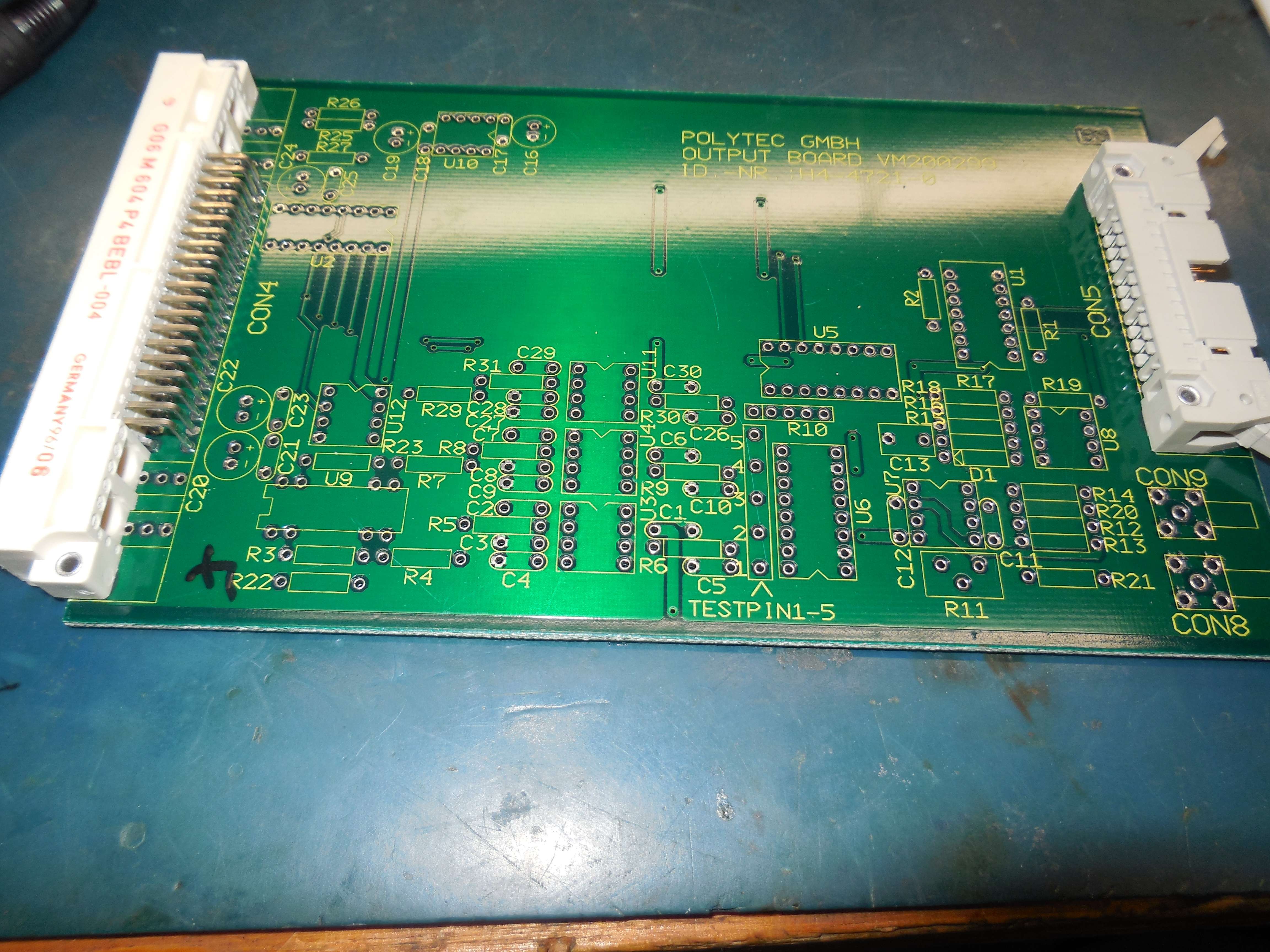
VM270-2400A Output Board (Unpopulated, Connection for LCD Panel)
VM270-2200A Master Oscillator (80 MHz to Bragg AOM)
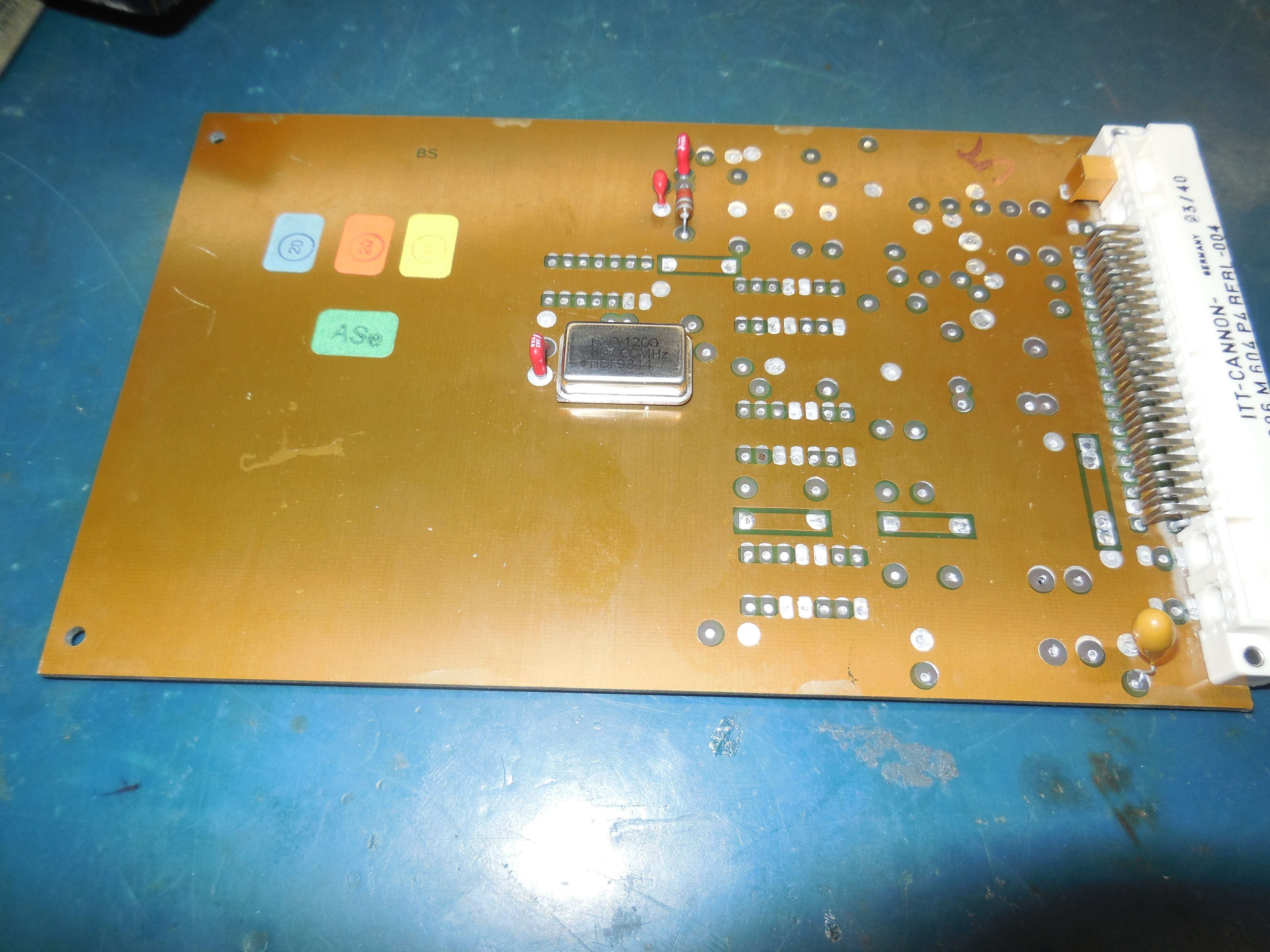
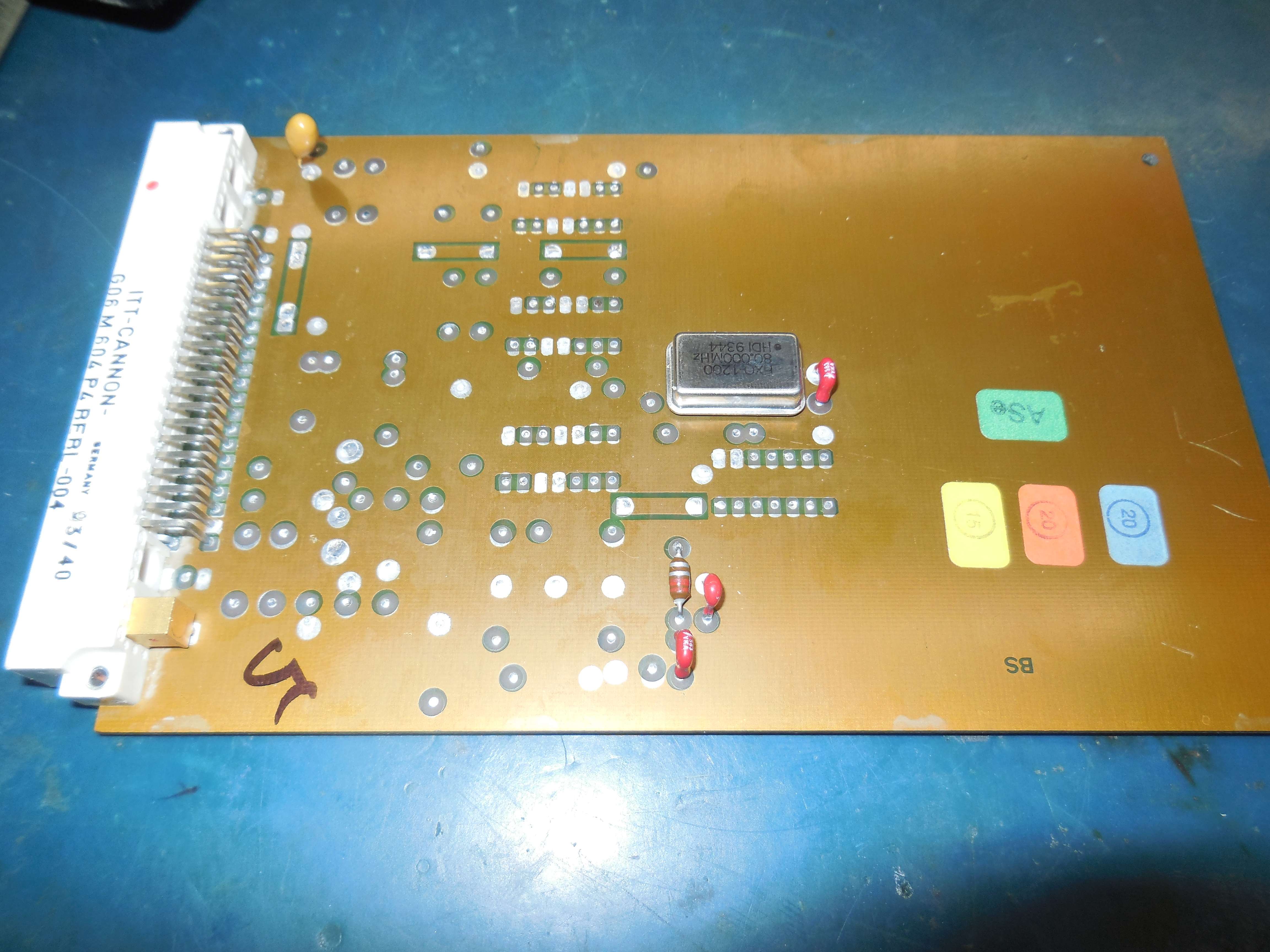
80 MHz clock oscillator through a LC low-pass filter and output to Bragg AOM.
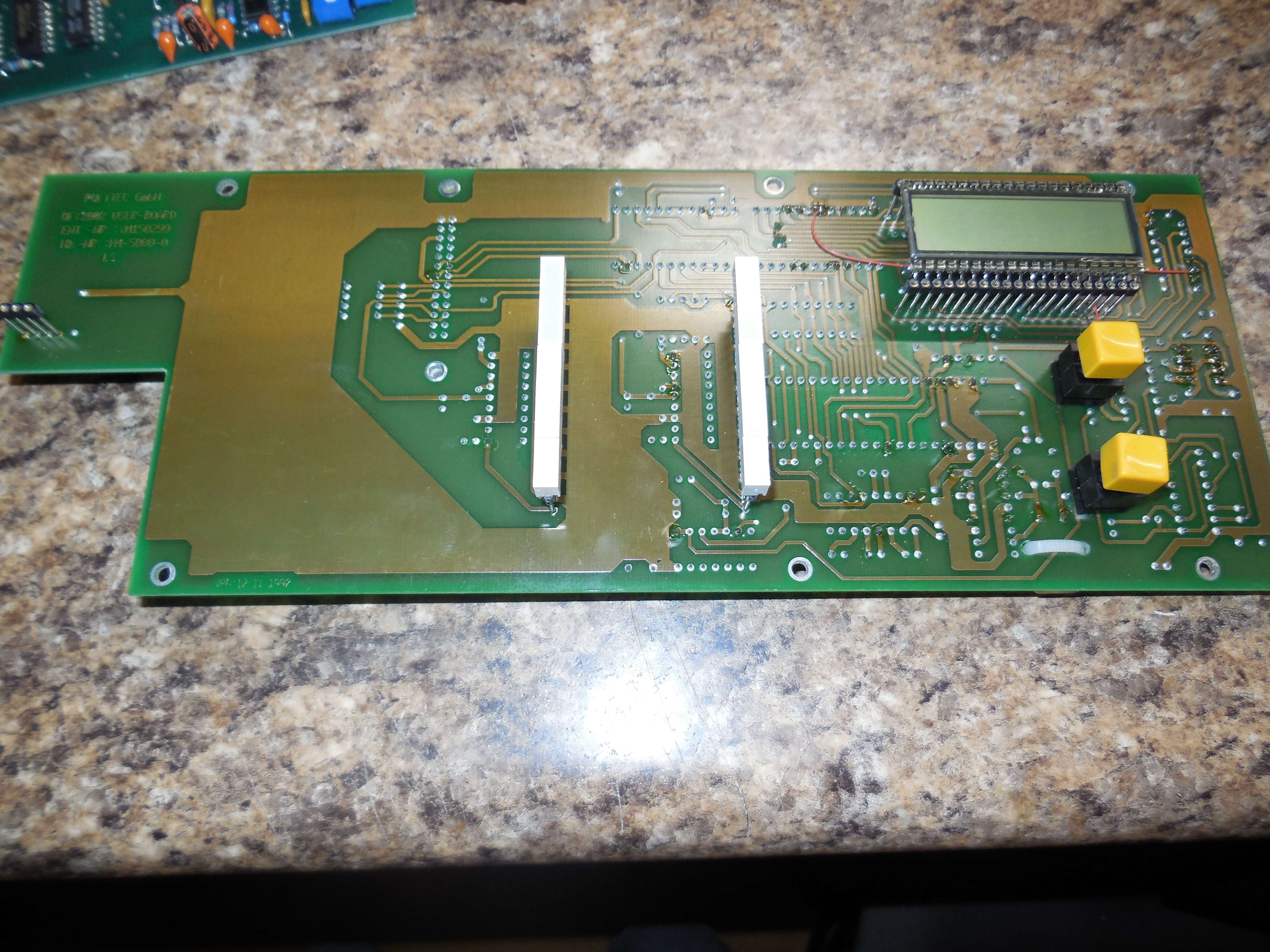
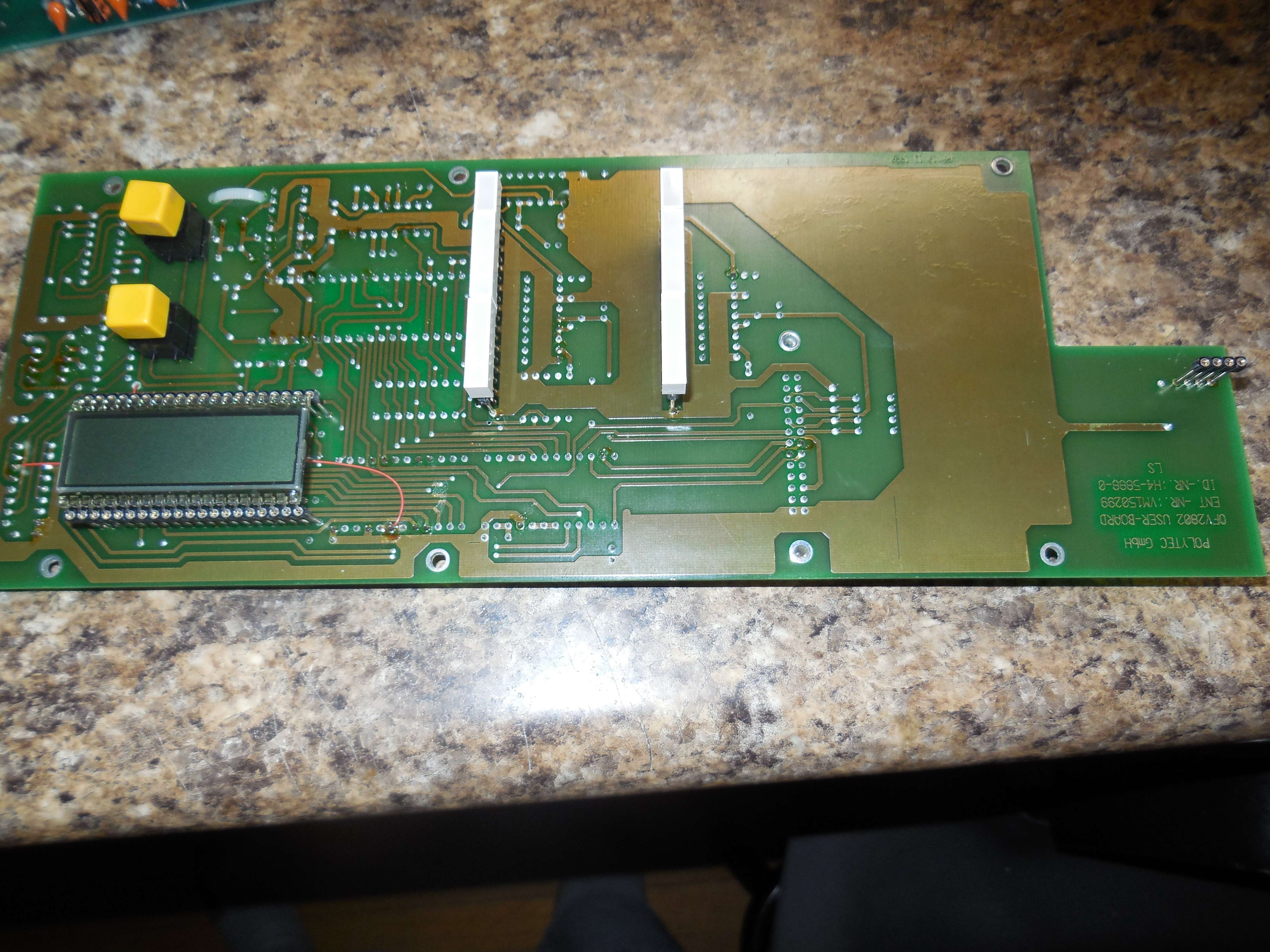
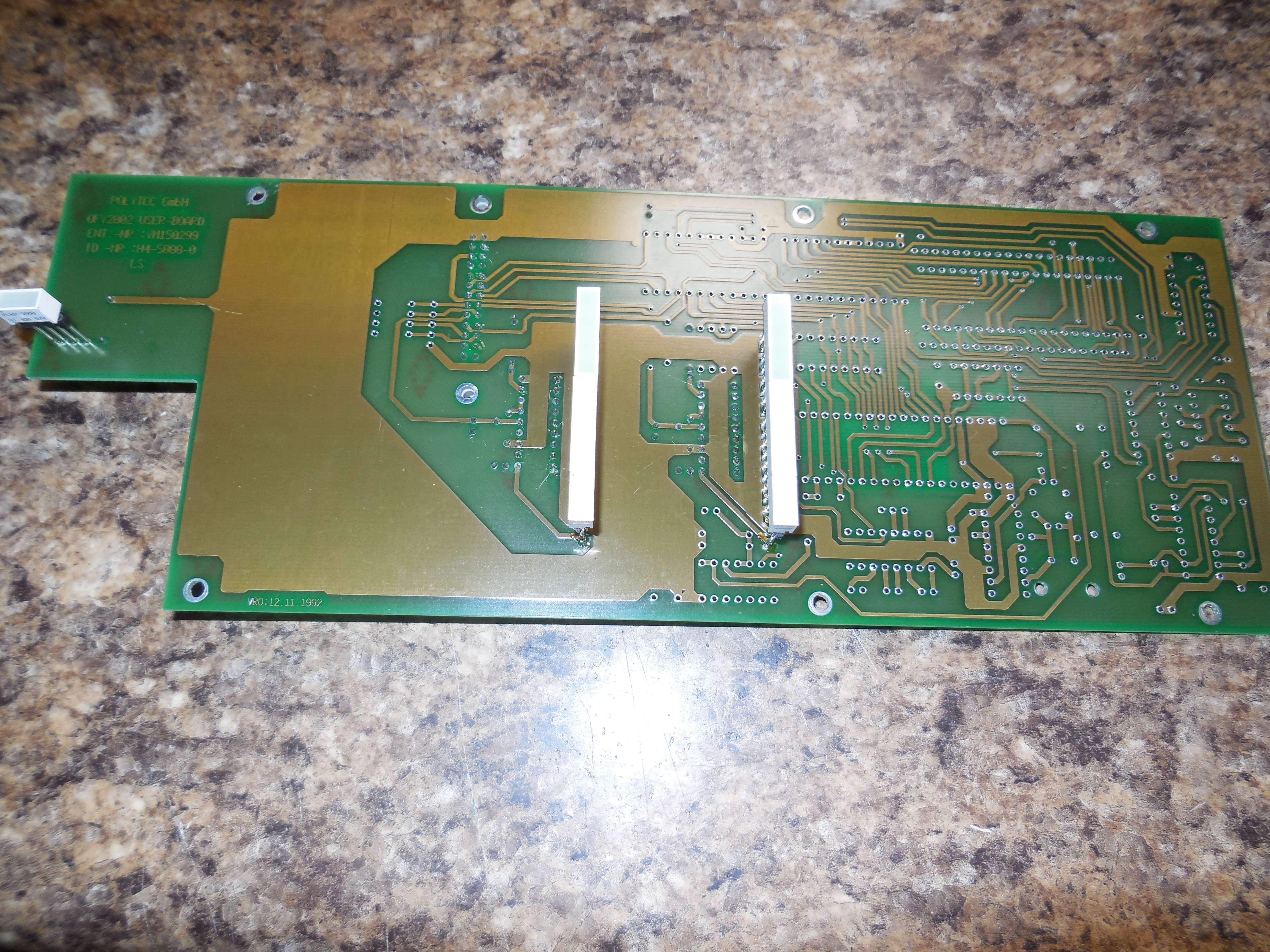
VM280-1400C Front-Panel

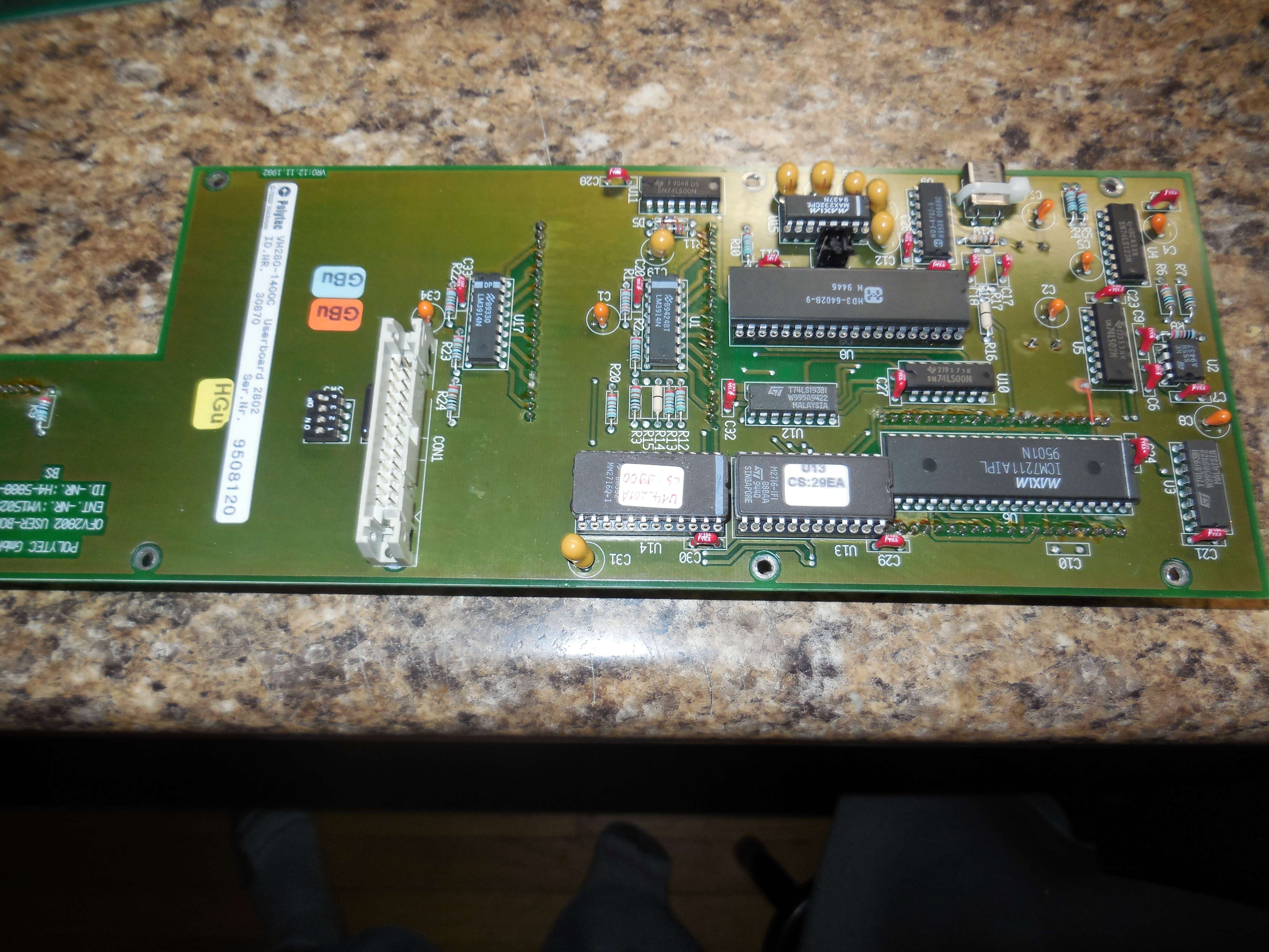
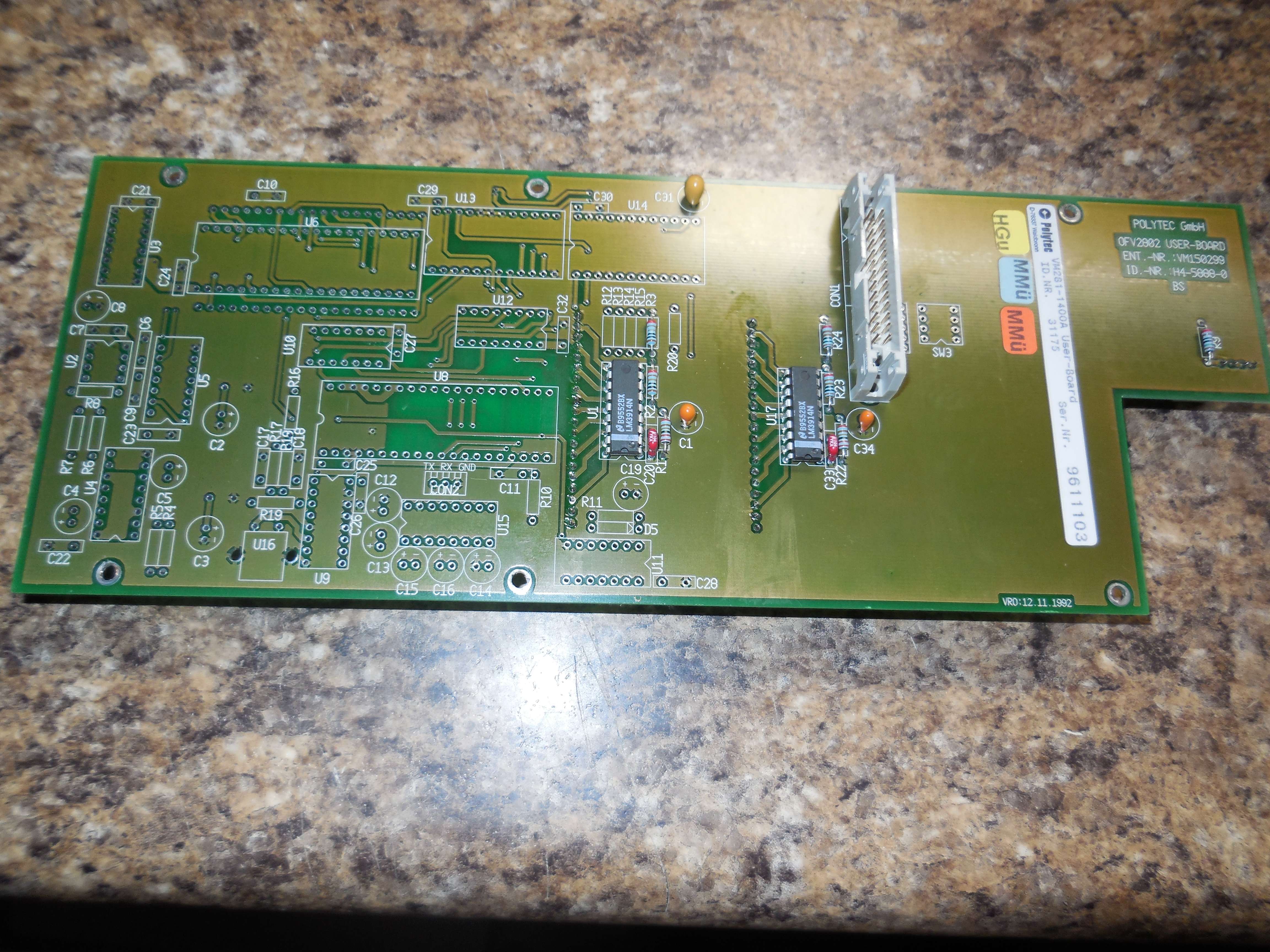
Harris HD3-6402B-9 UART, Maxim ICM7211 LCD driver, MAX232, LM3914, M2716 EPROMS.
On the bottom is a board without the LCD display circuits populated.
U13 EPROM Image M2716-IFI (CS: 29EA)
U14 EPROM Image MM2716Q-1 (CS: 9900)
VM270-2260A Master Oscillator (80 MHz to Bragg AOM)
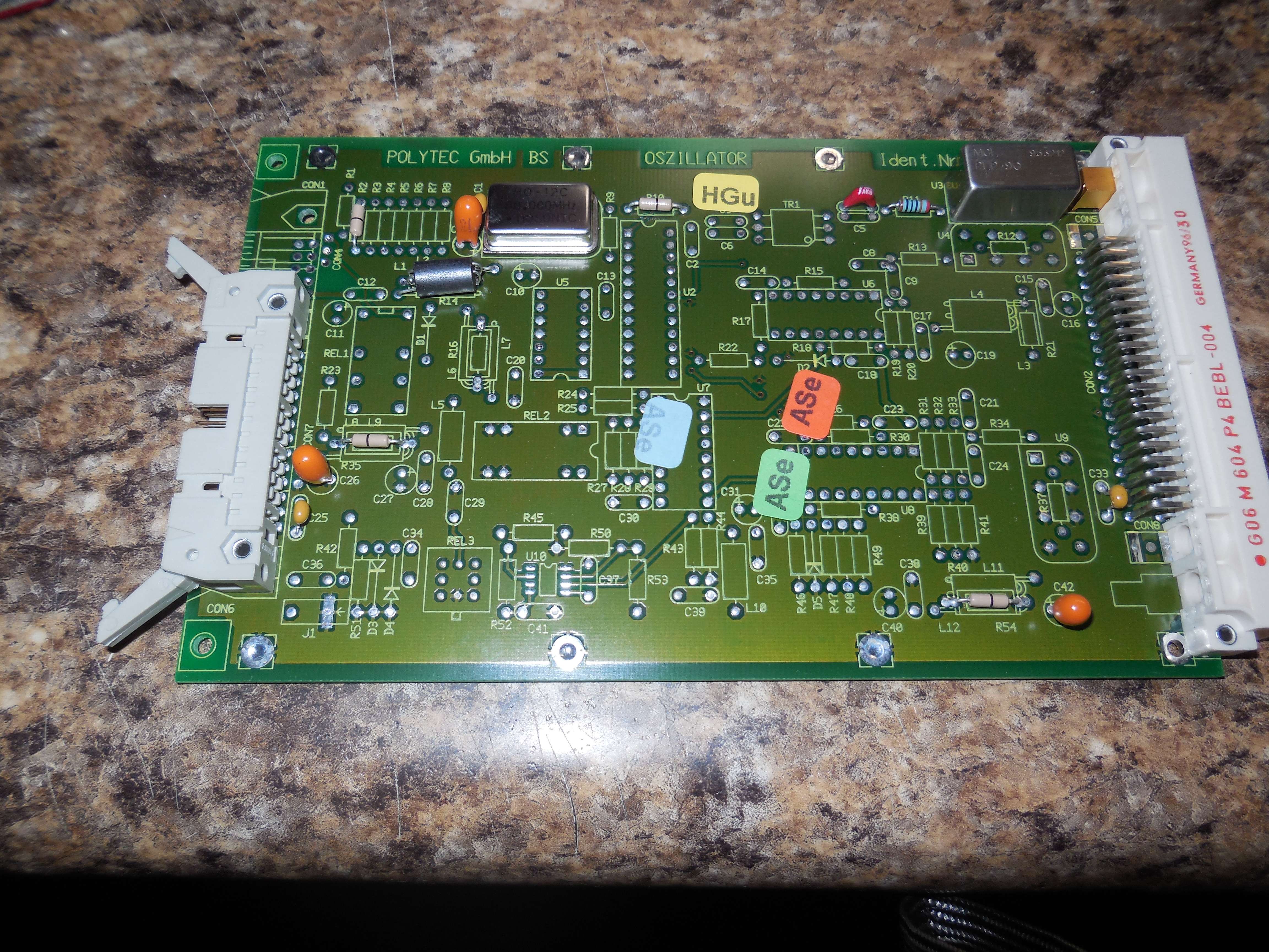
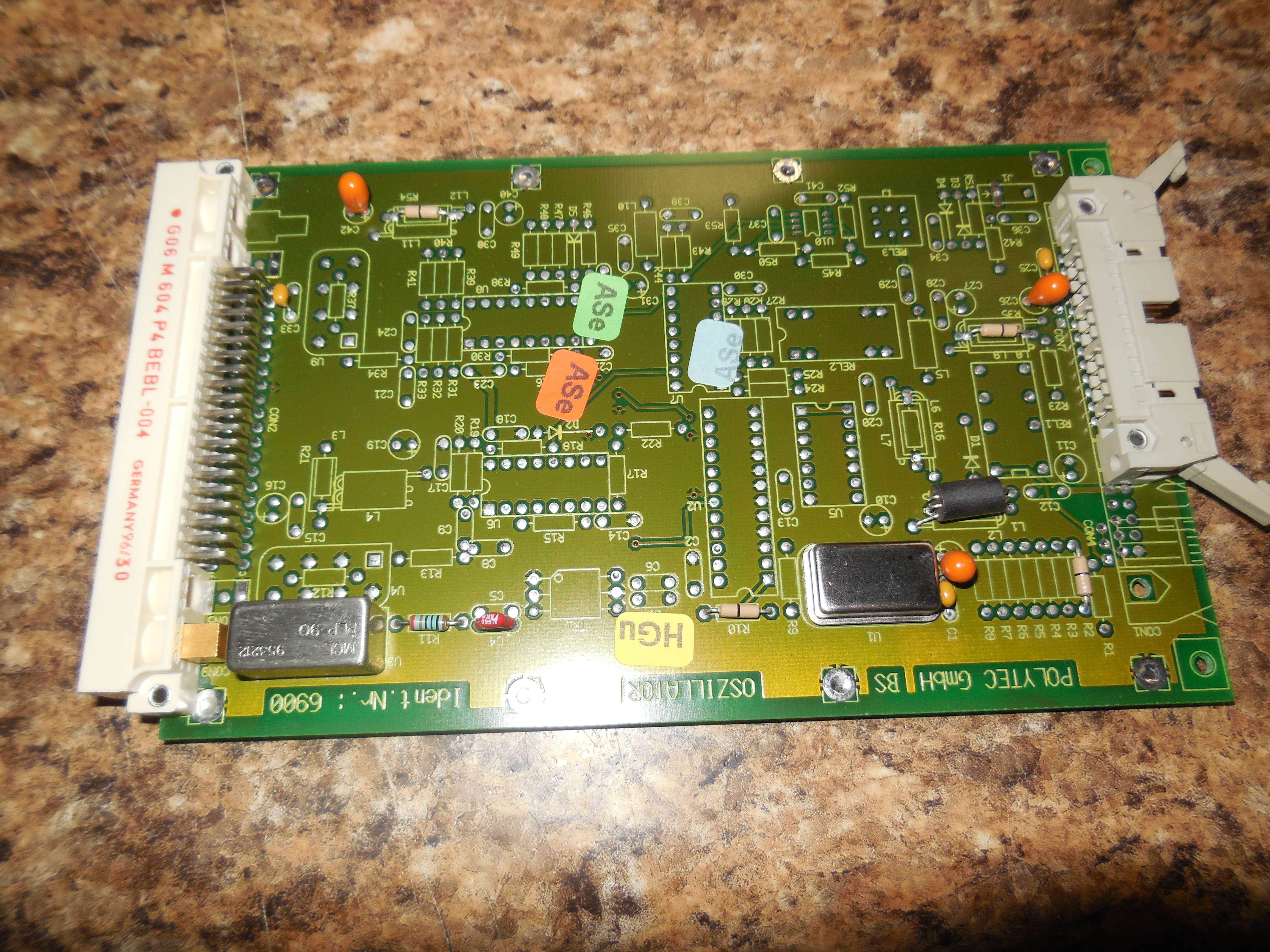
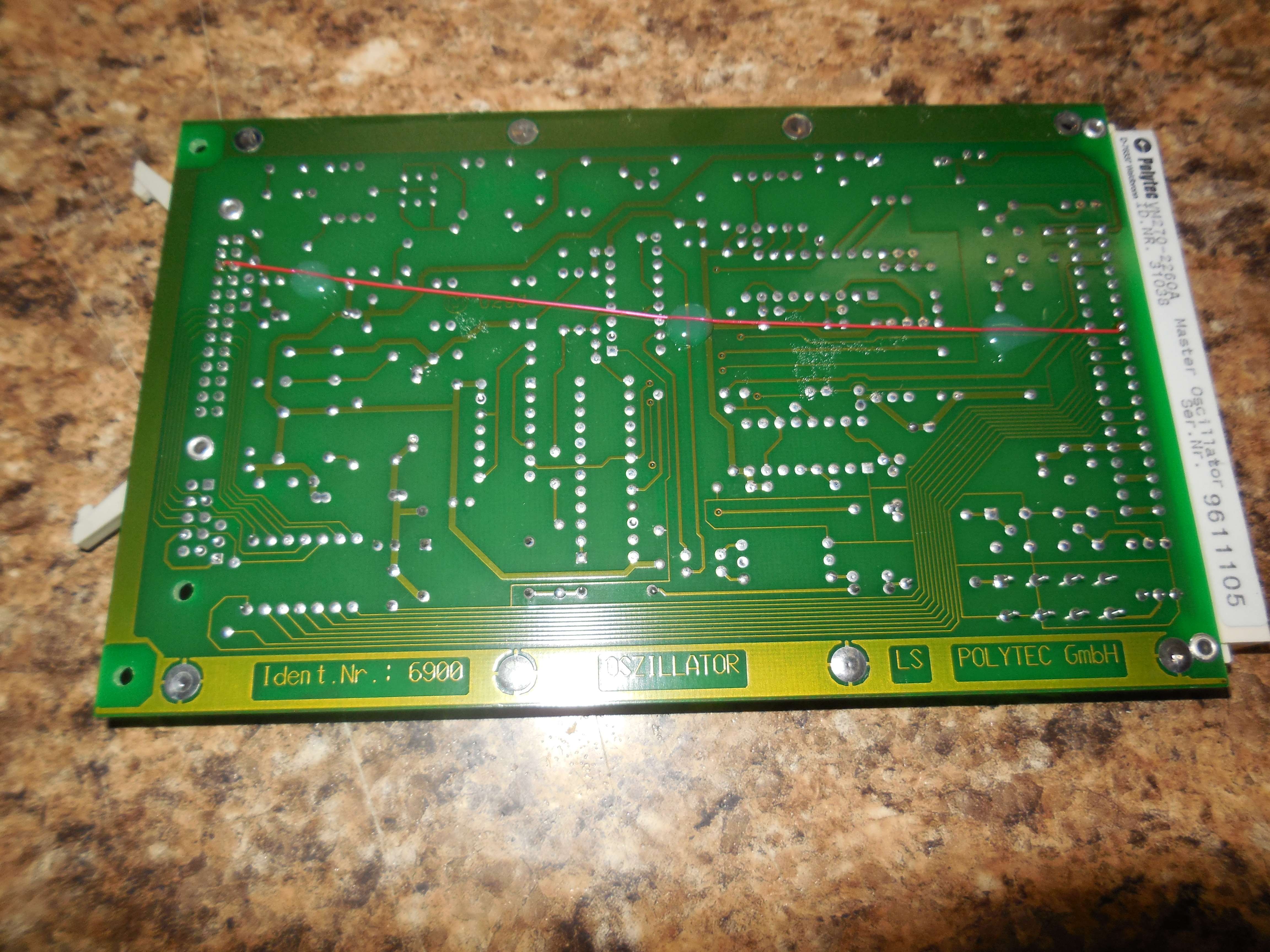
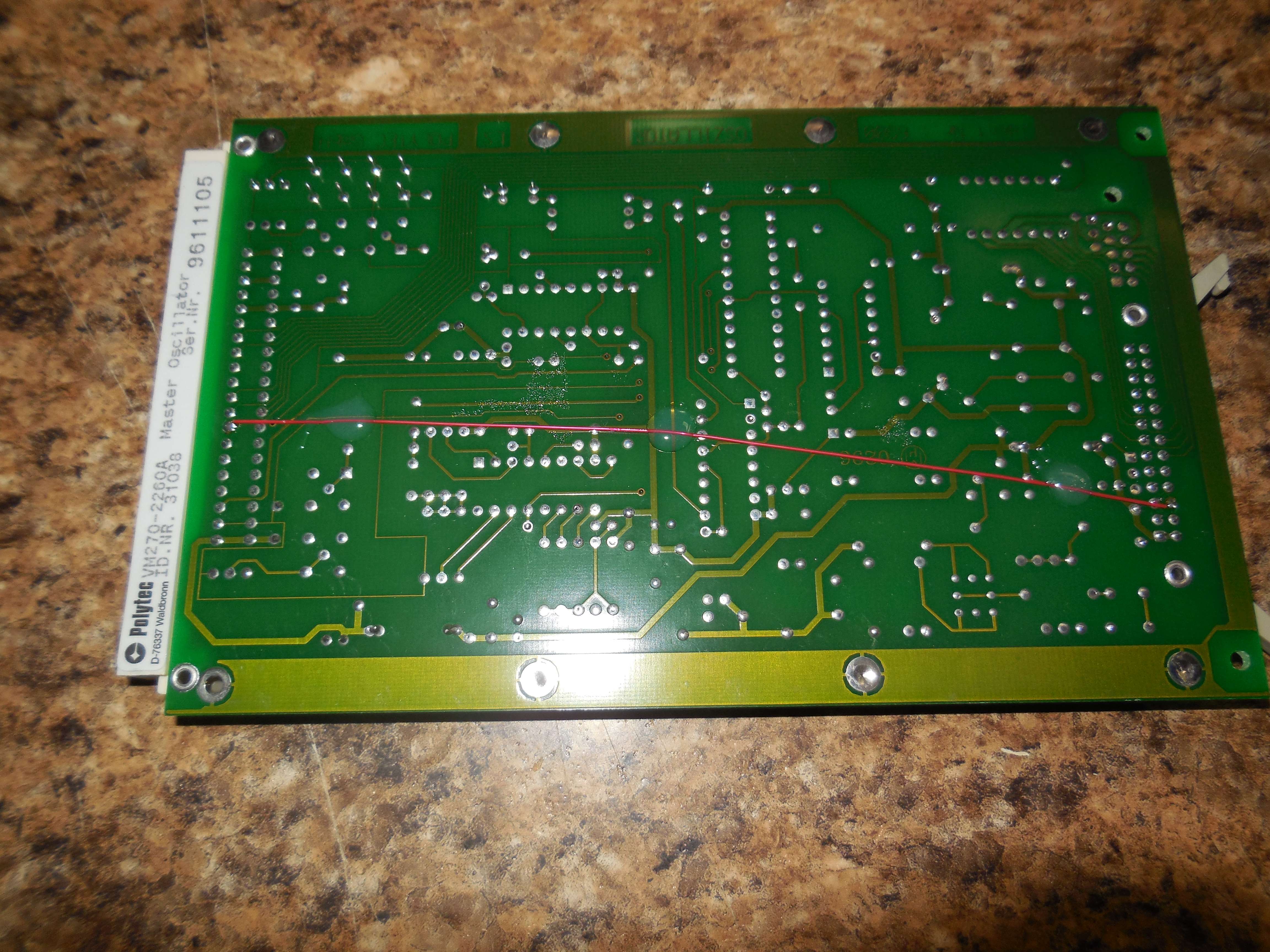
Alternate (newer?) 80 MHz master oscillator board.
HOSONIC HO-12C 80.000 MHz clock oscillator through a MCL PLP-90 low-pass filter and output to Bragg AOM.
The large connector is for the front-panel.
VM281-2510A Input Board
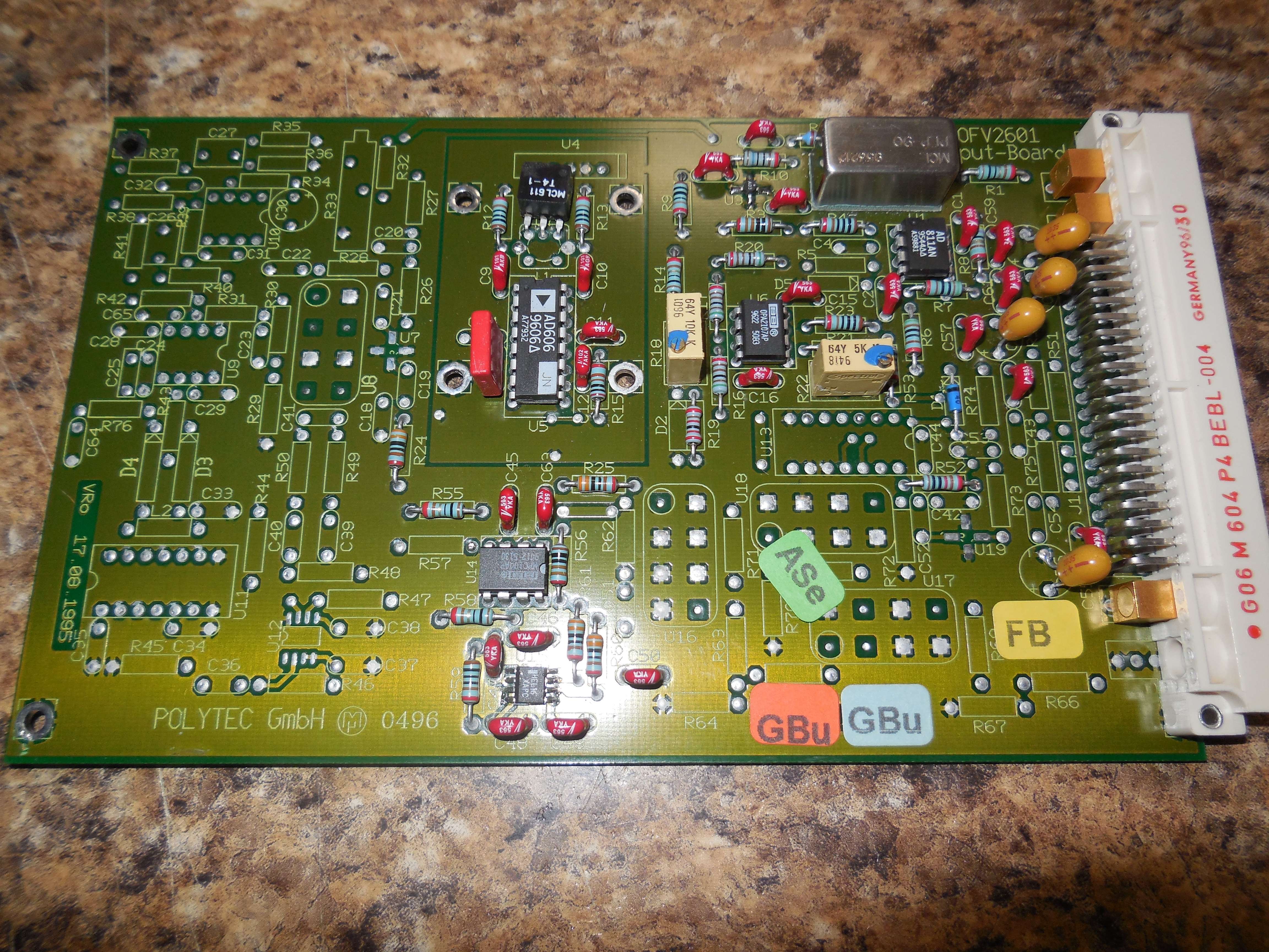
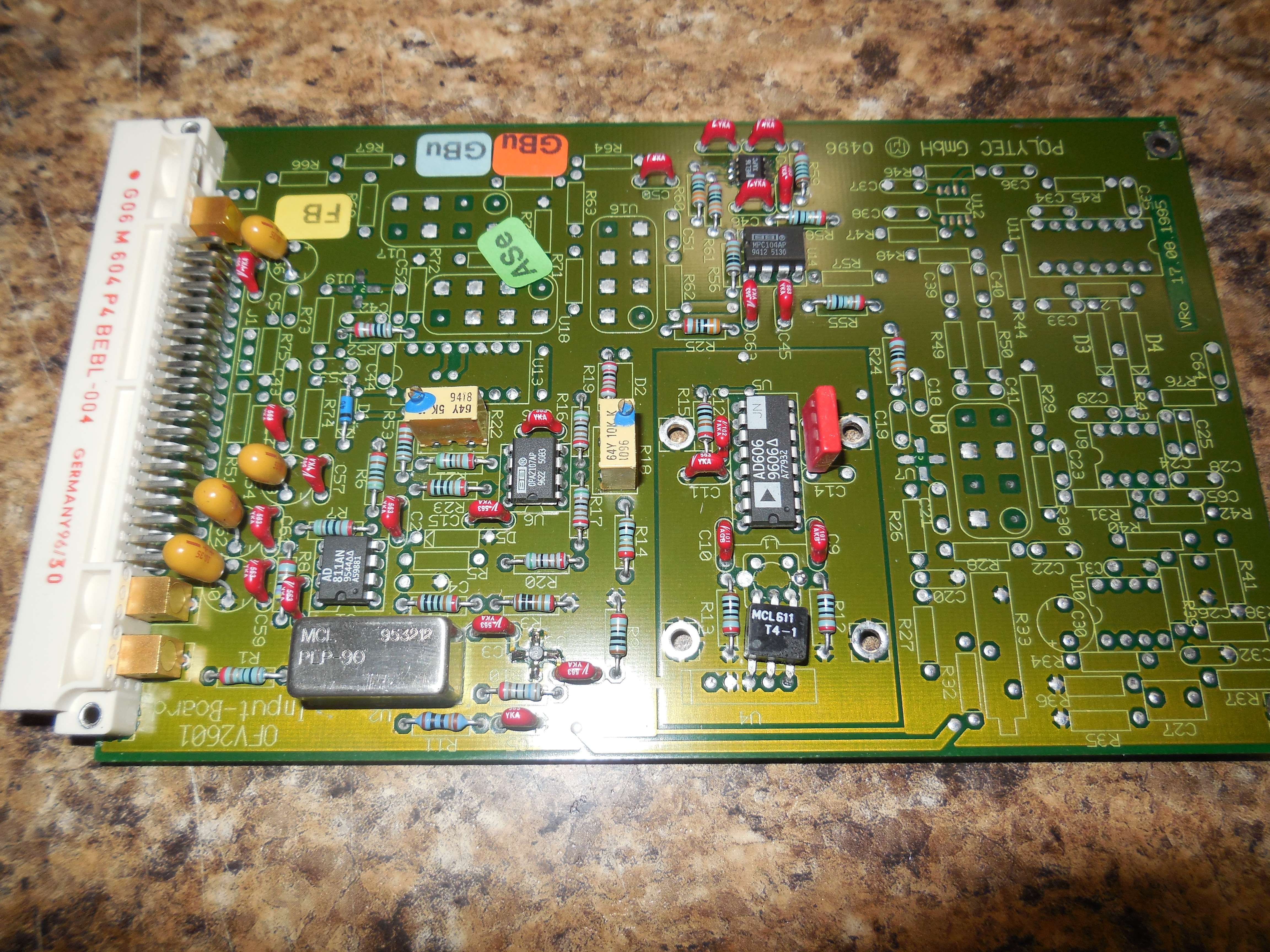
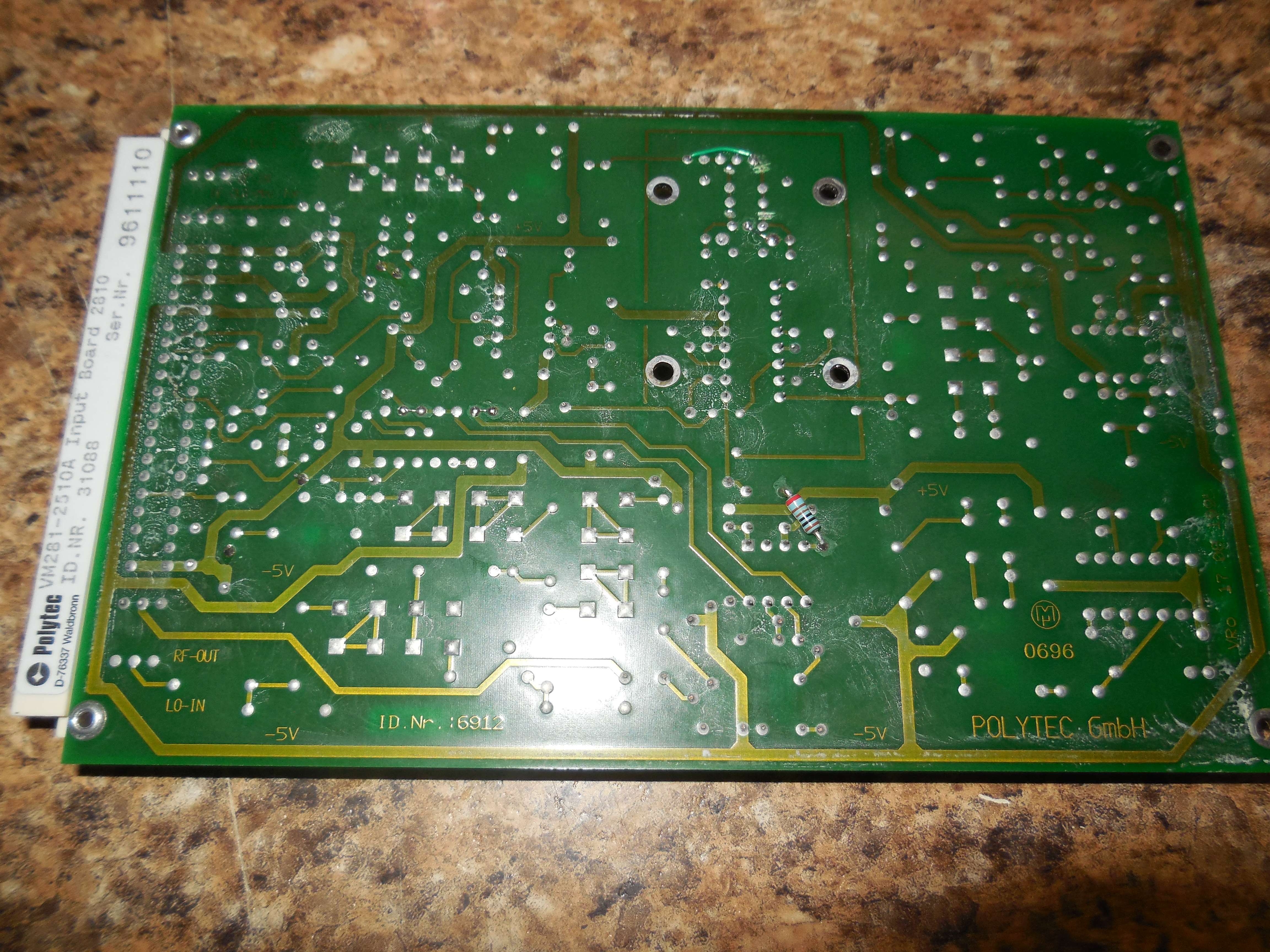
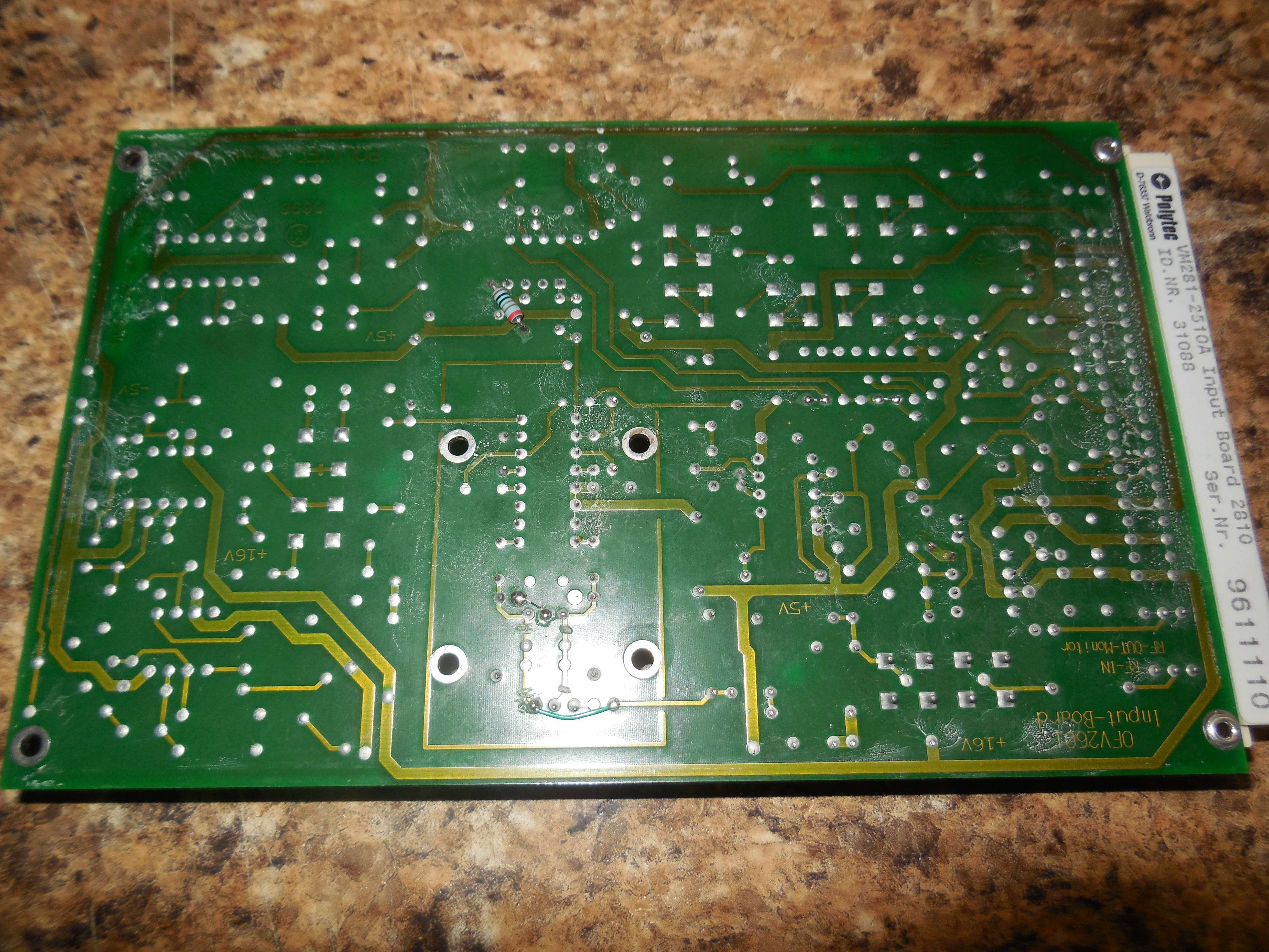
Alternate (newer?) input board.
Input through a MCL PLP-90, a MCL MAR-3 MMIC, a MCL T4-1 transformer and into an Analog Devices AD606, then MPC104, and finally a HEL16. (may not be right)
VM281-6200A HF Demodulator (Input) (OVD-05)
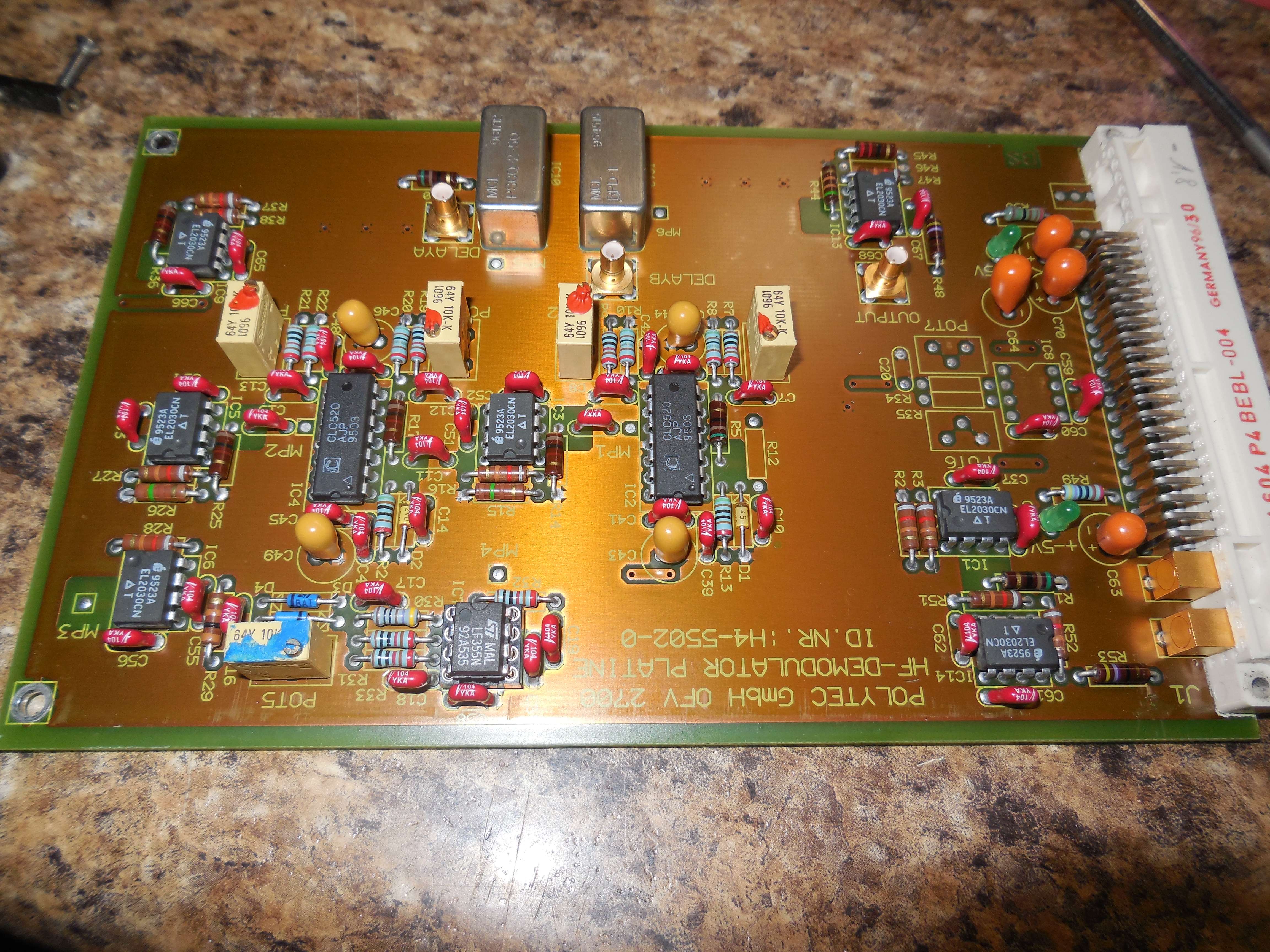
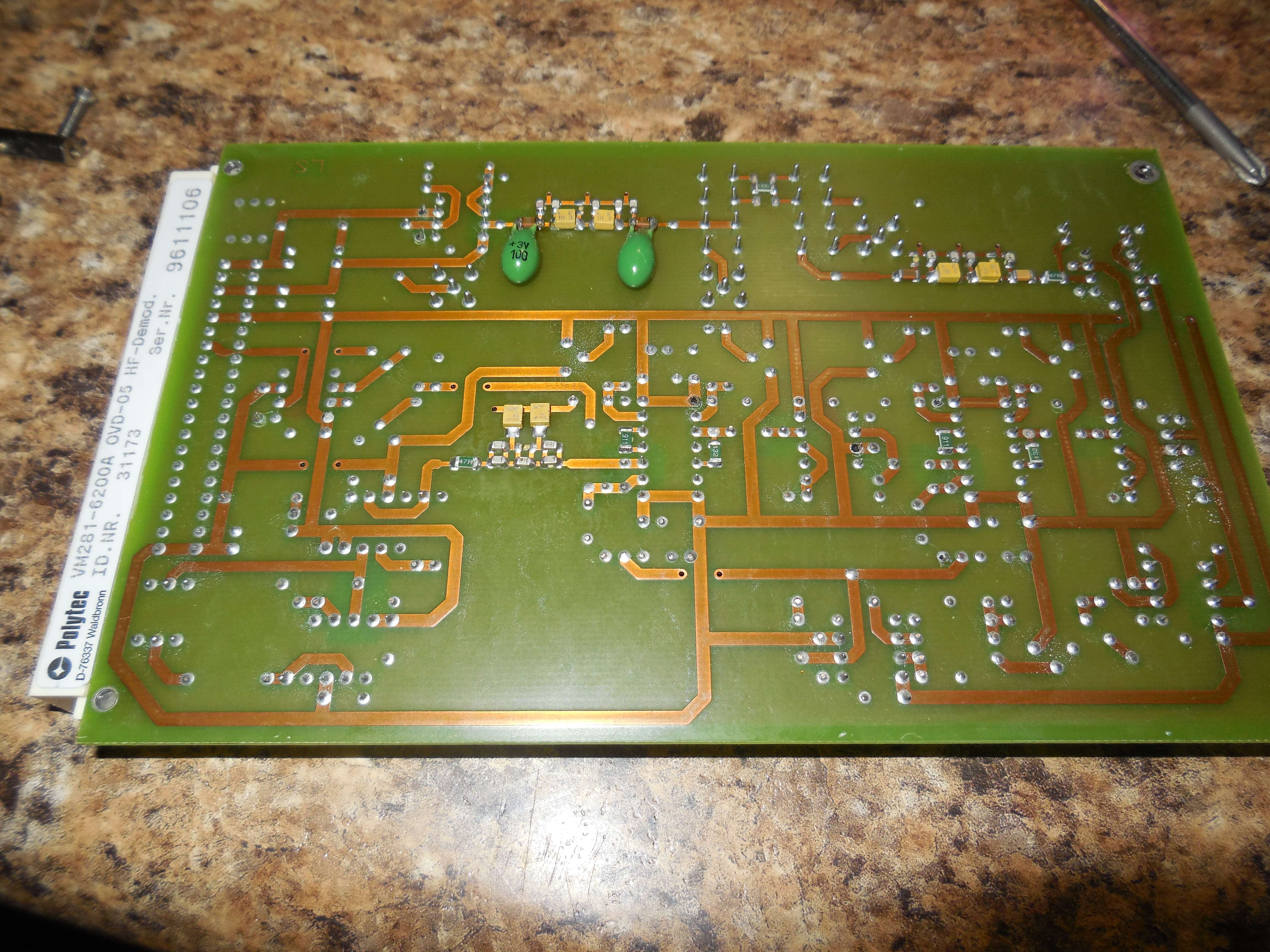
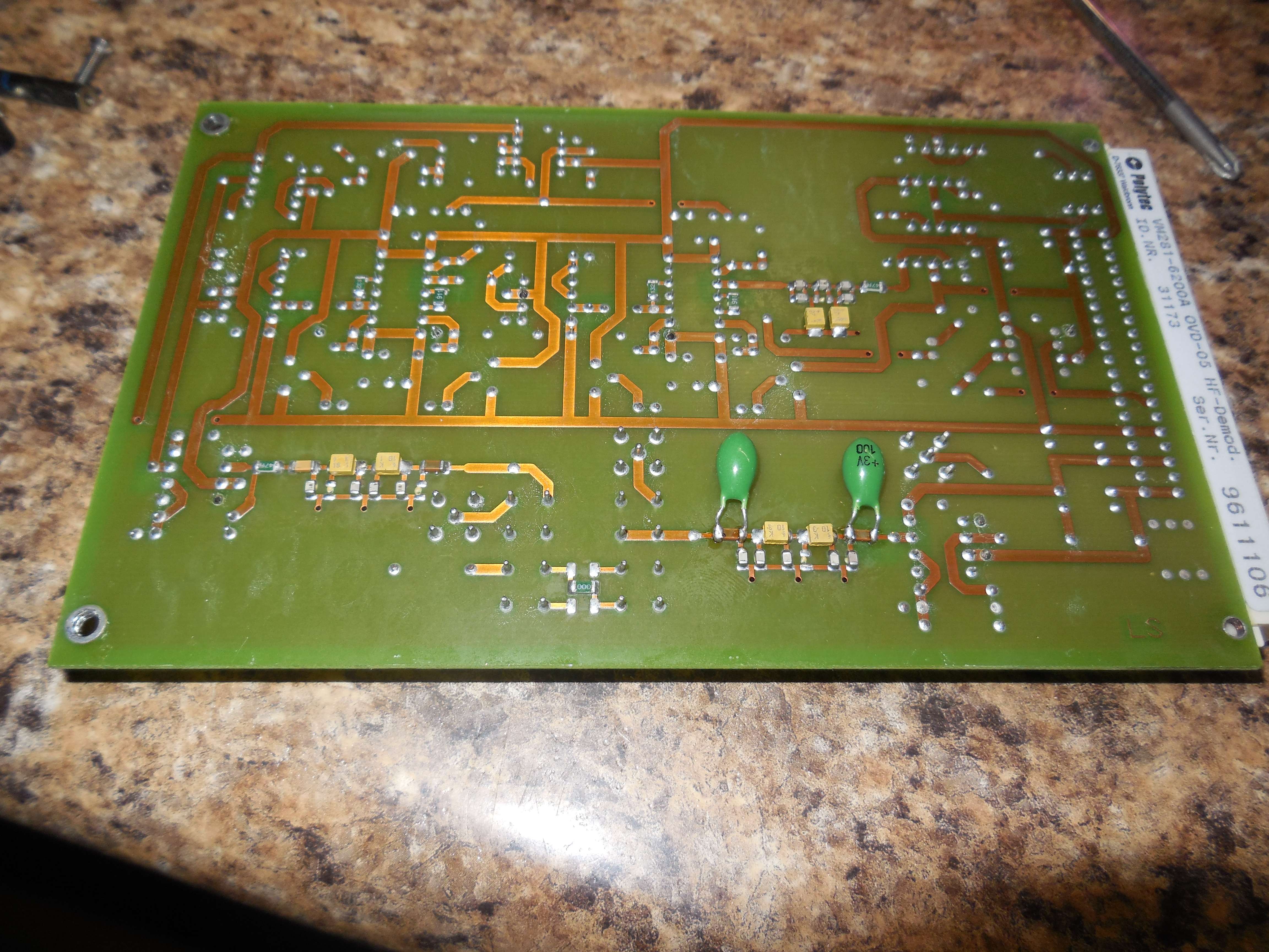
Alternate (newer?) HF demodulator board.
Frequency discriminator (frequency-to-voltage) via a coaxial delay line and 90° phase shift into the MCL RPD-1.
EL2030, CLC520, LF355, MCL RPD-1, MCL PSCQ-2-50.
Both channels, "Channel A" and "Channel B" use the same hardware.
DFE-650 DSP Front End
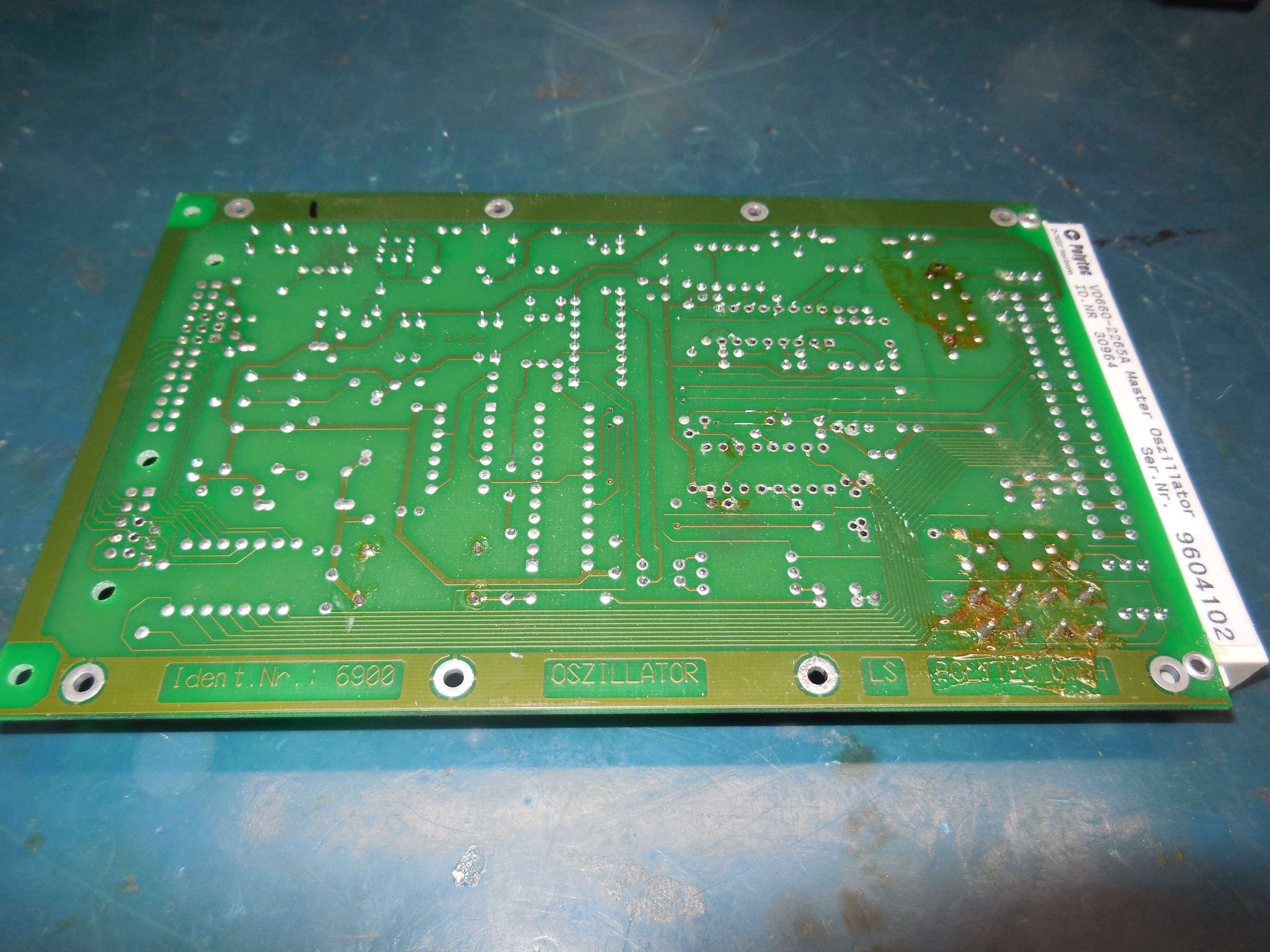
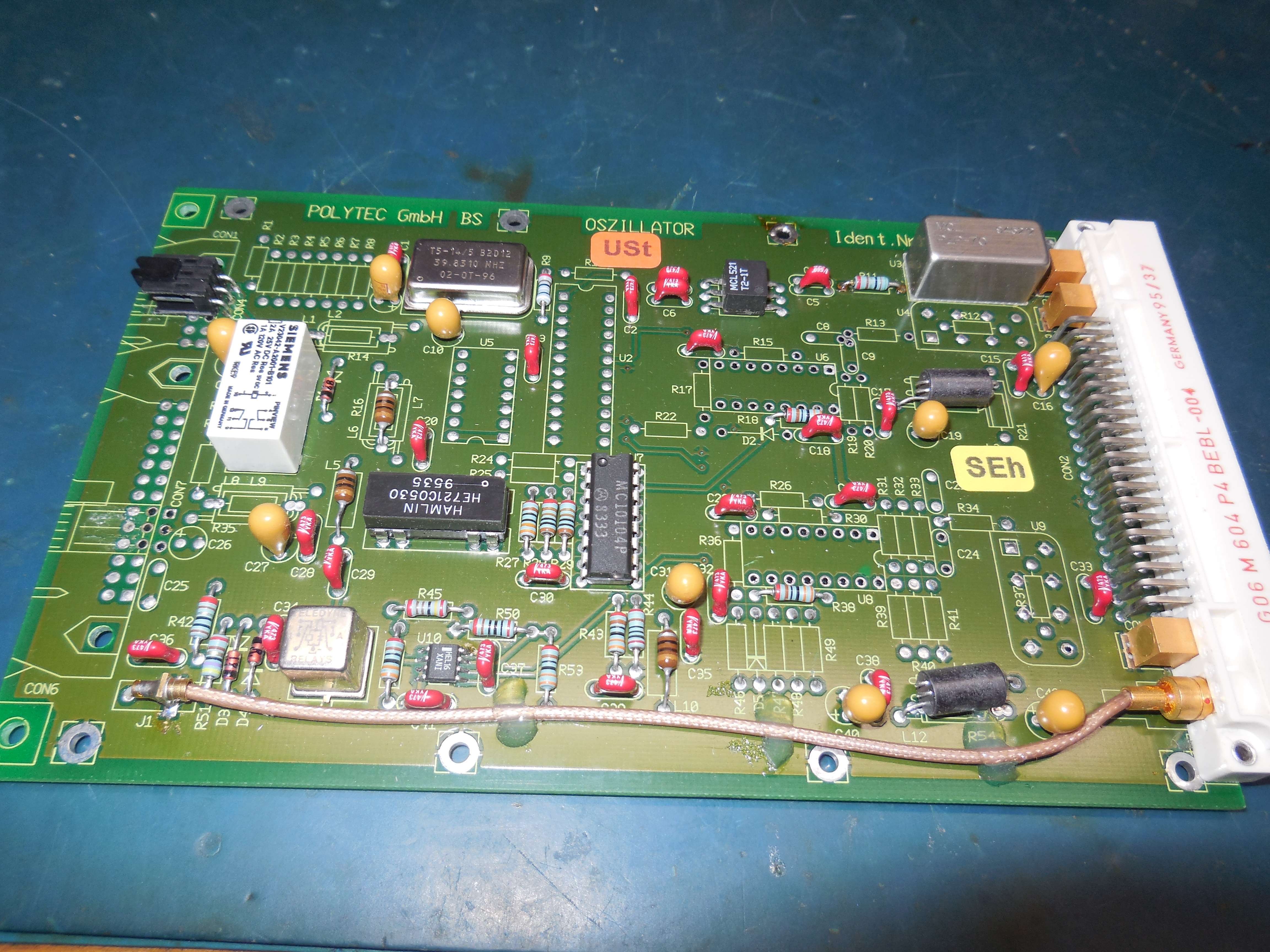
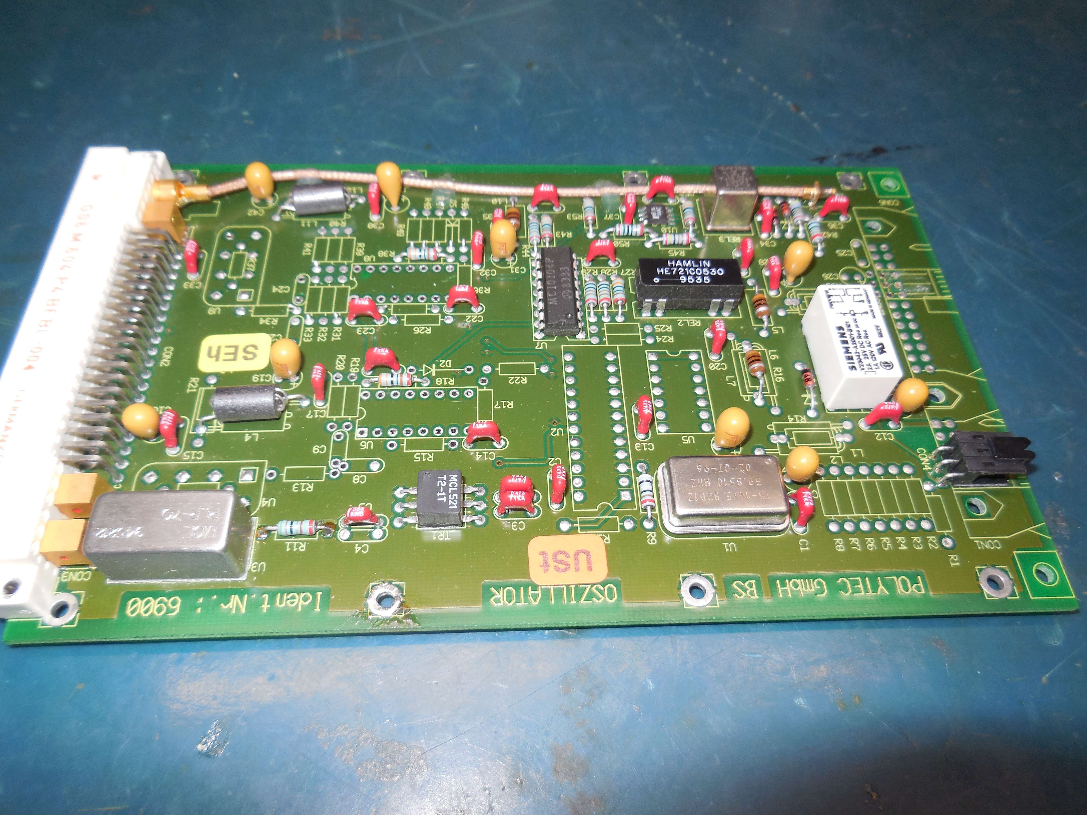
VM265-2265A Master Oscillator (80 MHz to Bragg AOM)
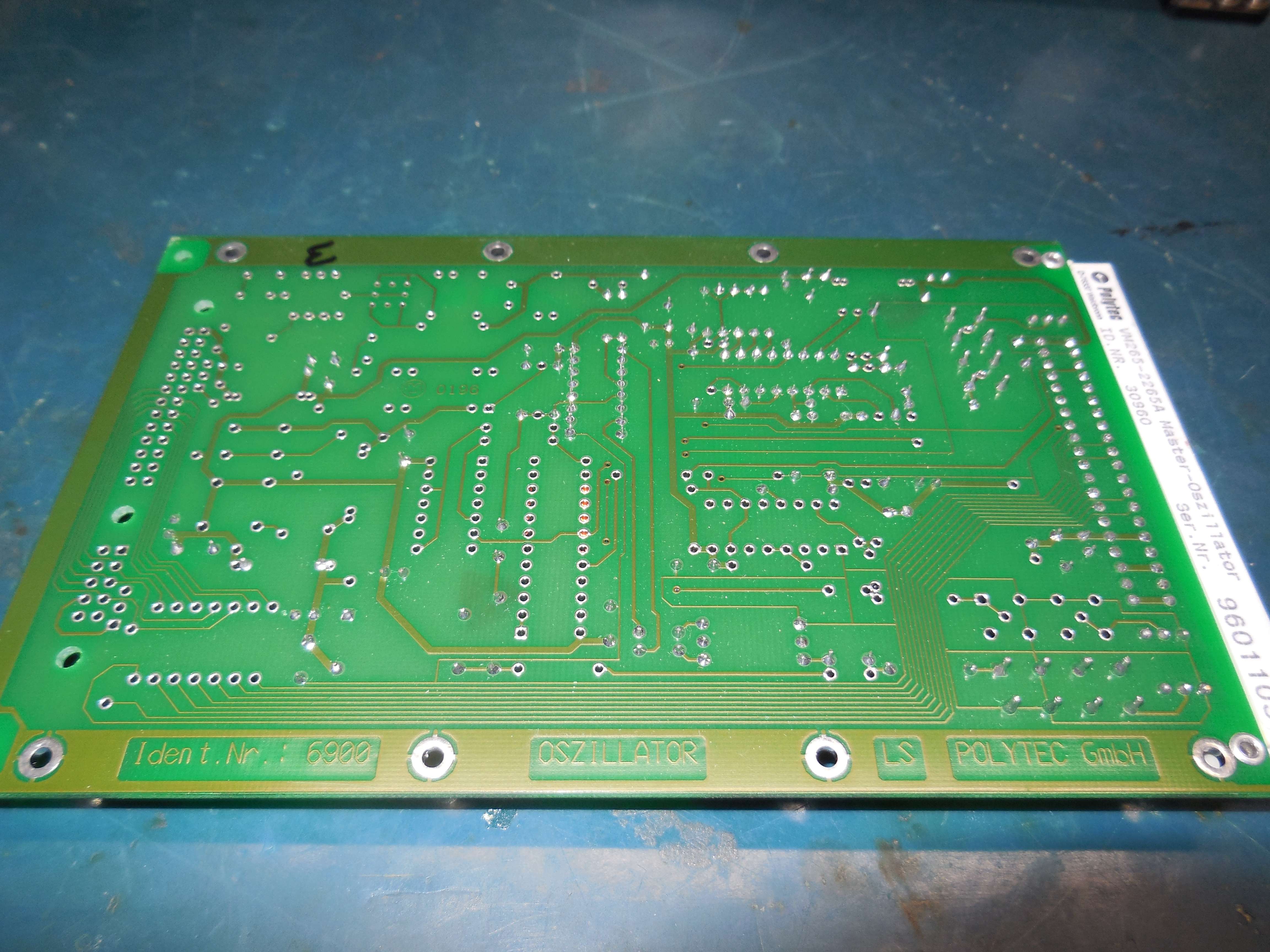
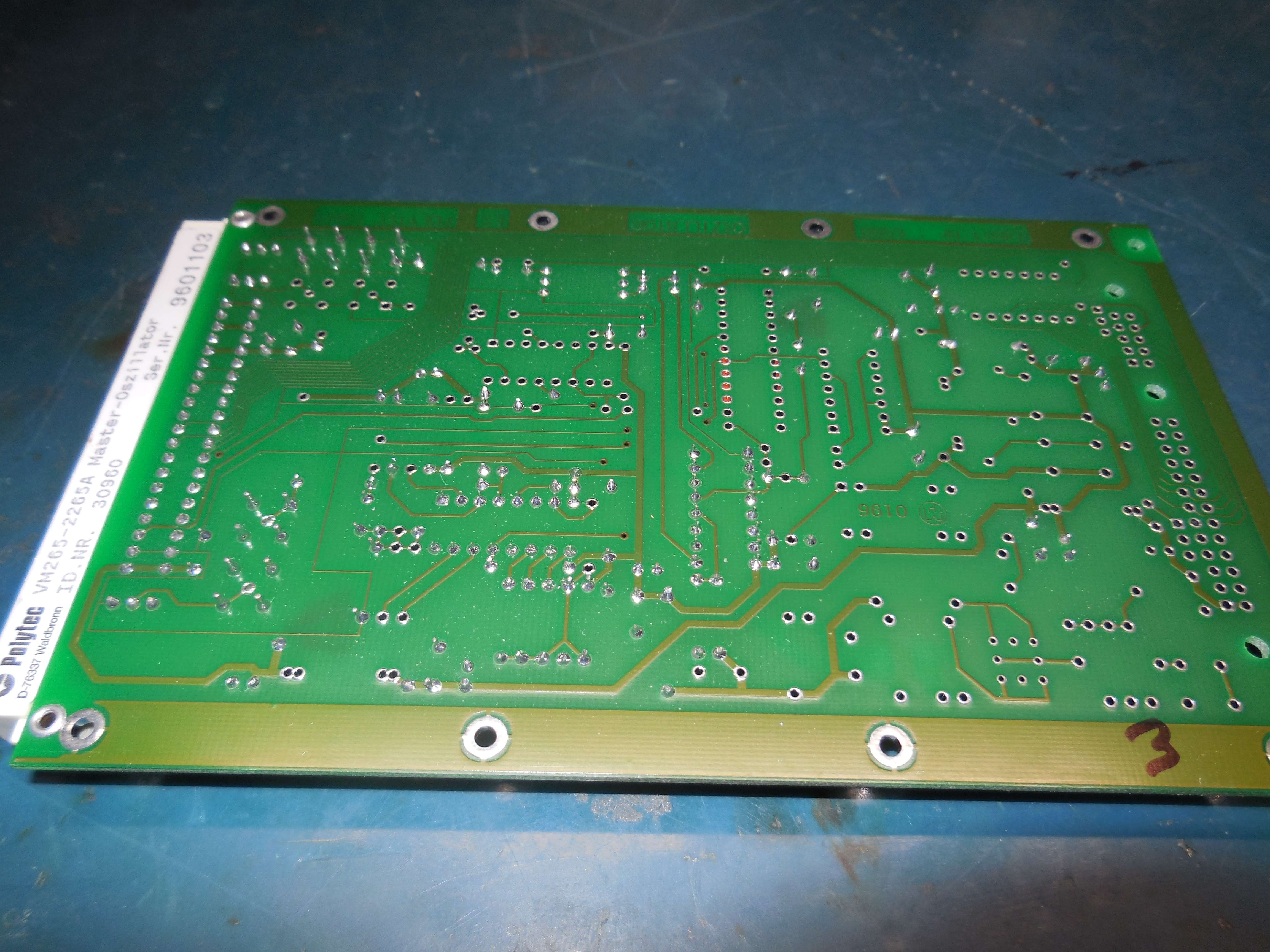
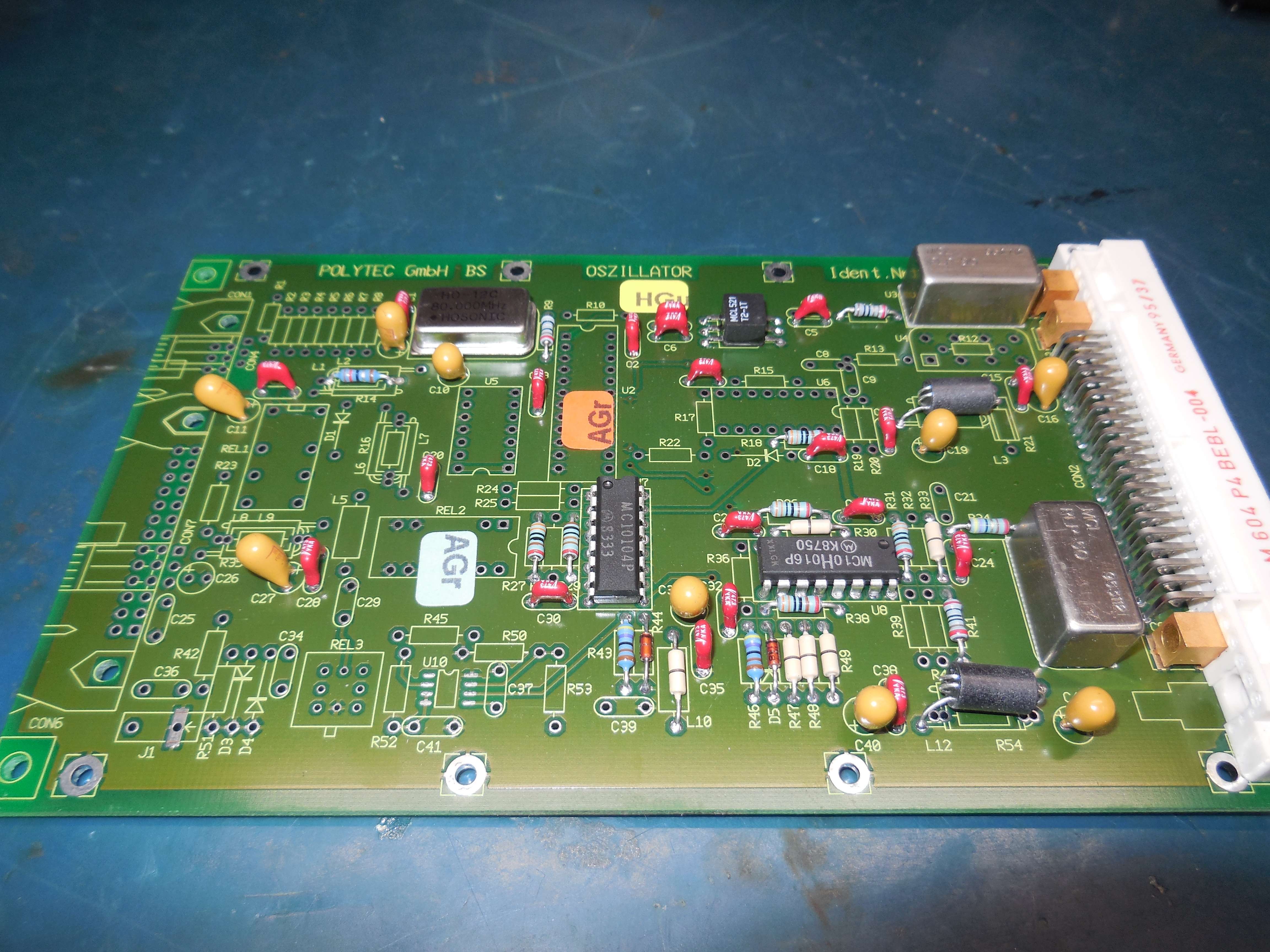
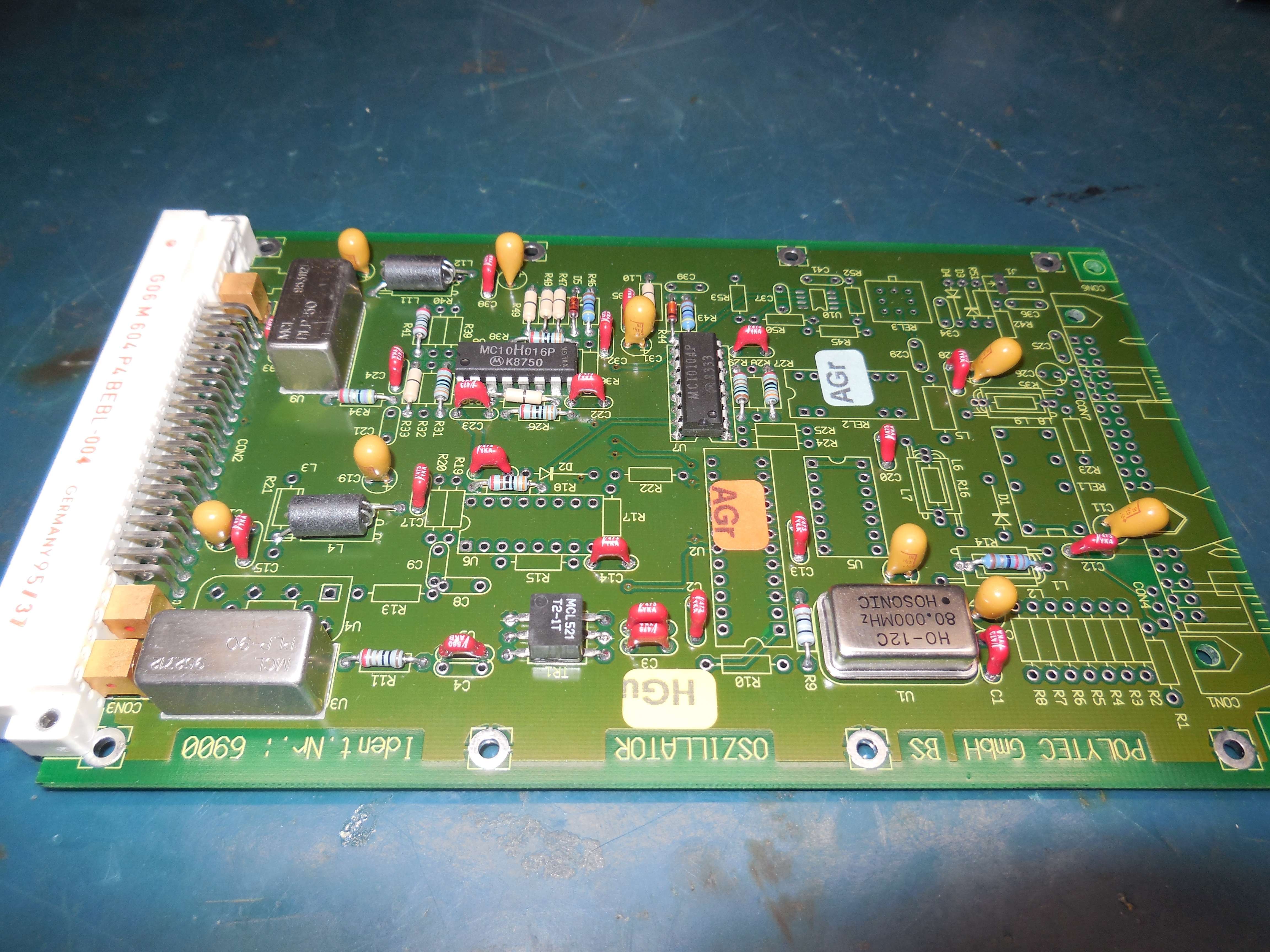
80 MHz clock oscillator, MC10H104 2-input NAND gate, MC10H016 4-bit binary counter, MCL PLP-50, MCL PLP-90
DFE-0650-QD11A Quadrature Demodulator
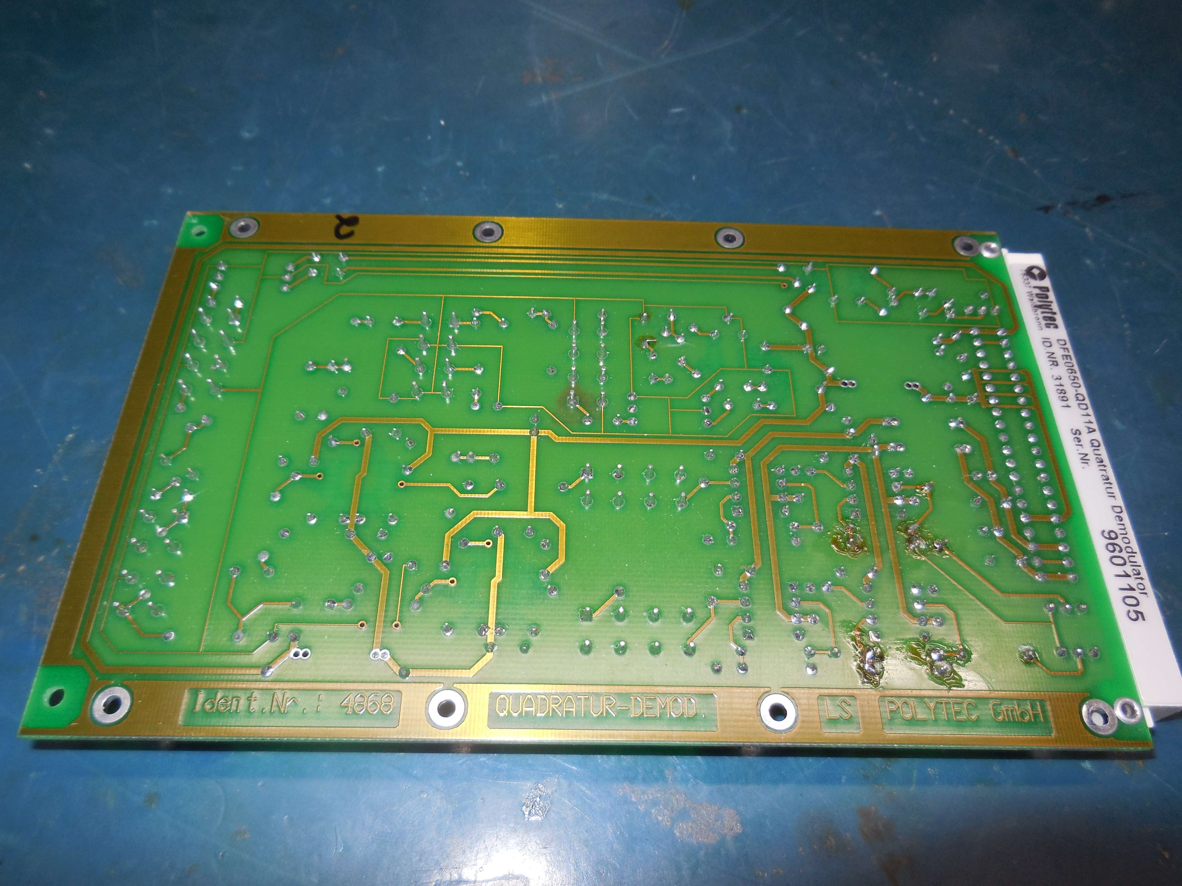
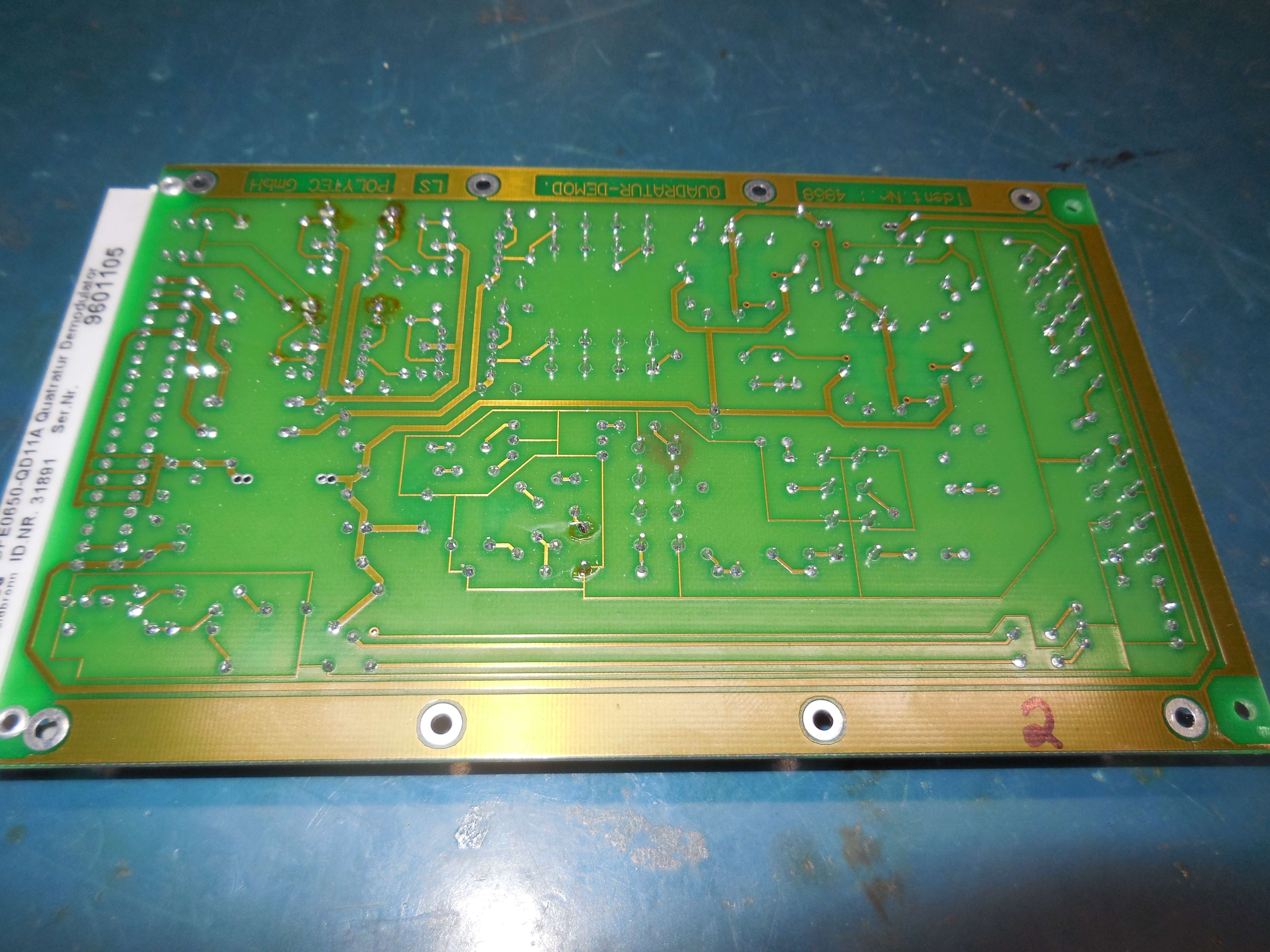
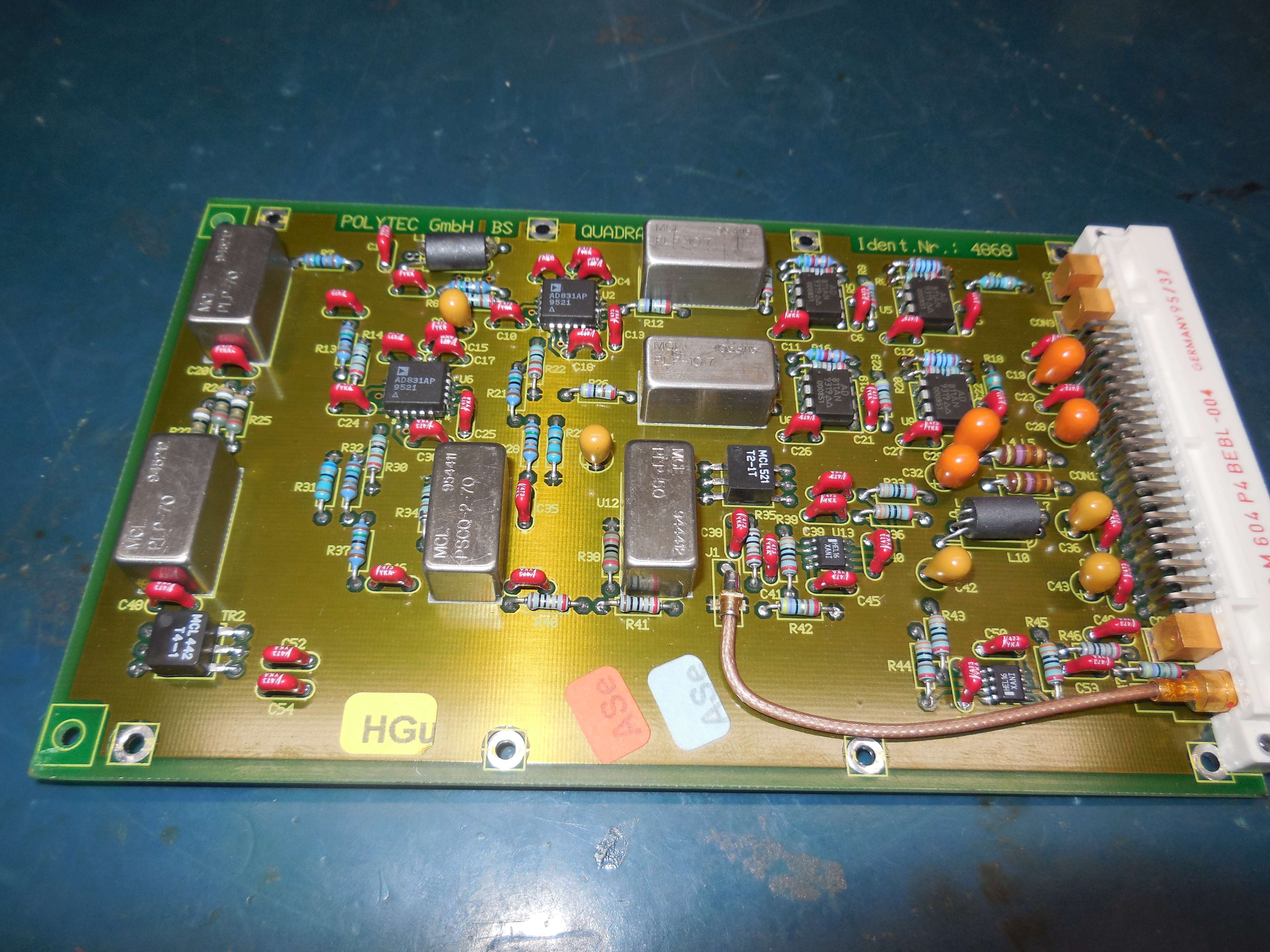
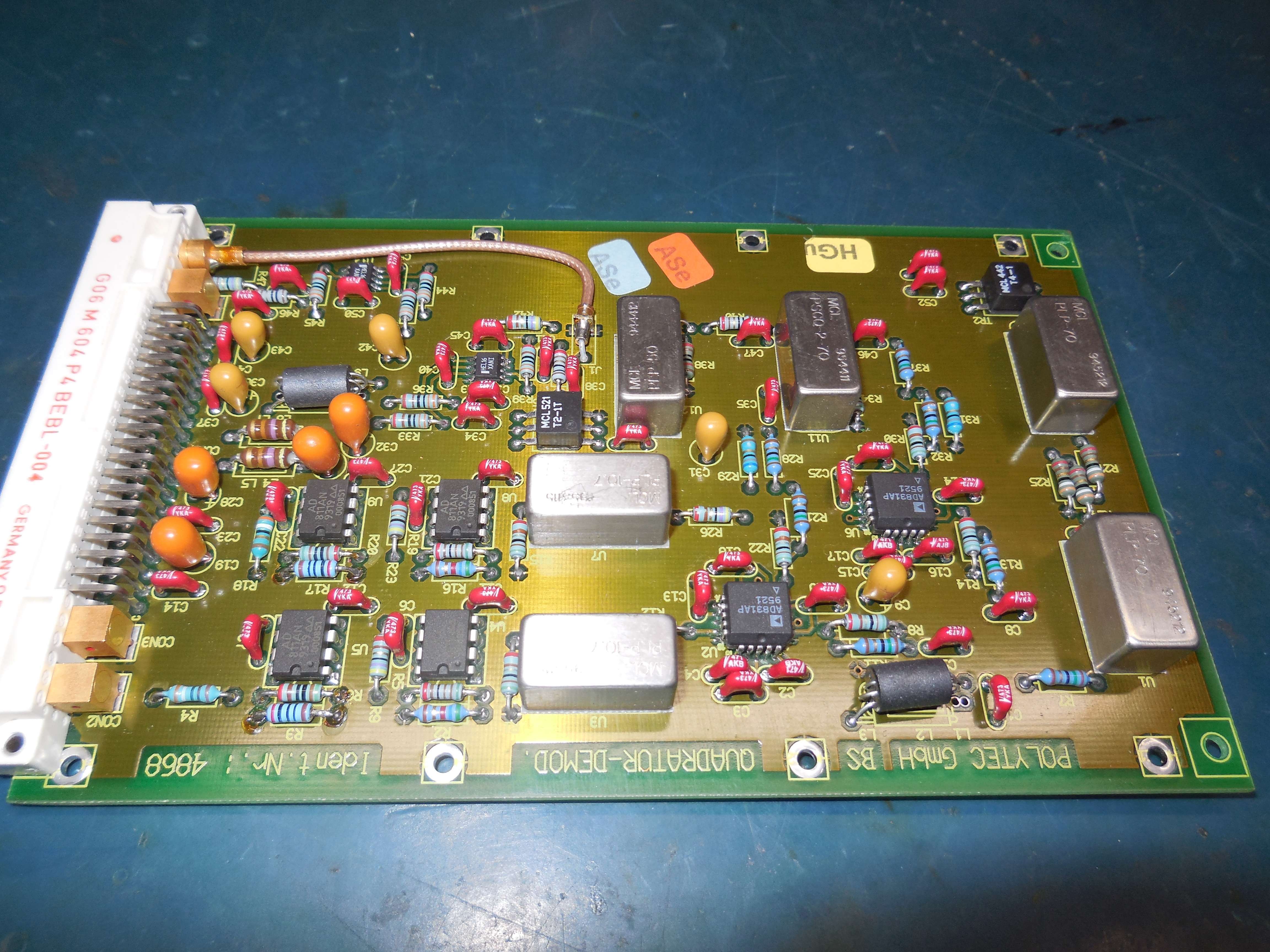
I believe this takes the 39.831 MHz LO, splits it to 0° and 90° for LOs to the AD831. Signal to AD831 RF input and IF out through 10.7 LPF and AD811 buffers. The IF output (40.000 MHz - 39.831 MHz = 168 kHz) is sent to rear-panel mounted fringe counter (displacment) output??
AD831, AD811, Motorola HEL16 (?), MCL PSCQ-2-70, MCL PLP-50, MCL PLP-70, MCL PLP-10.7, MCL T2-1T
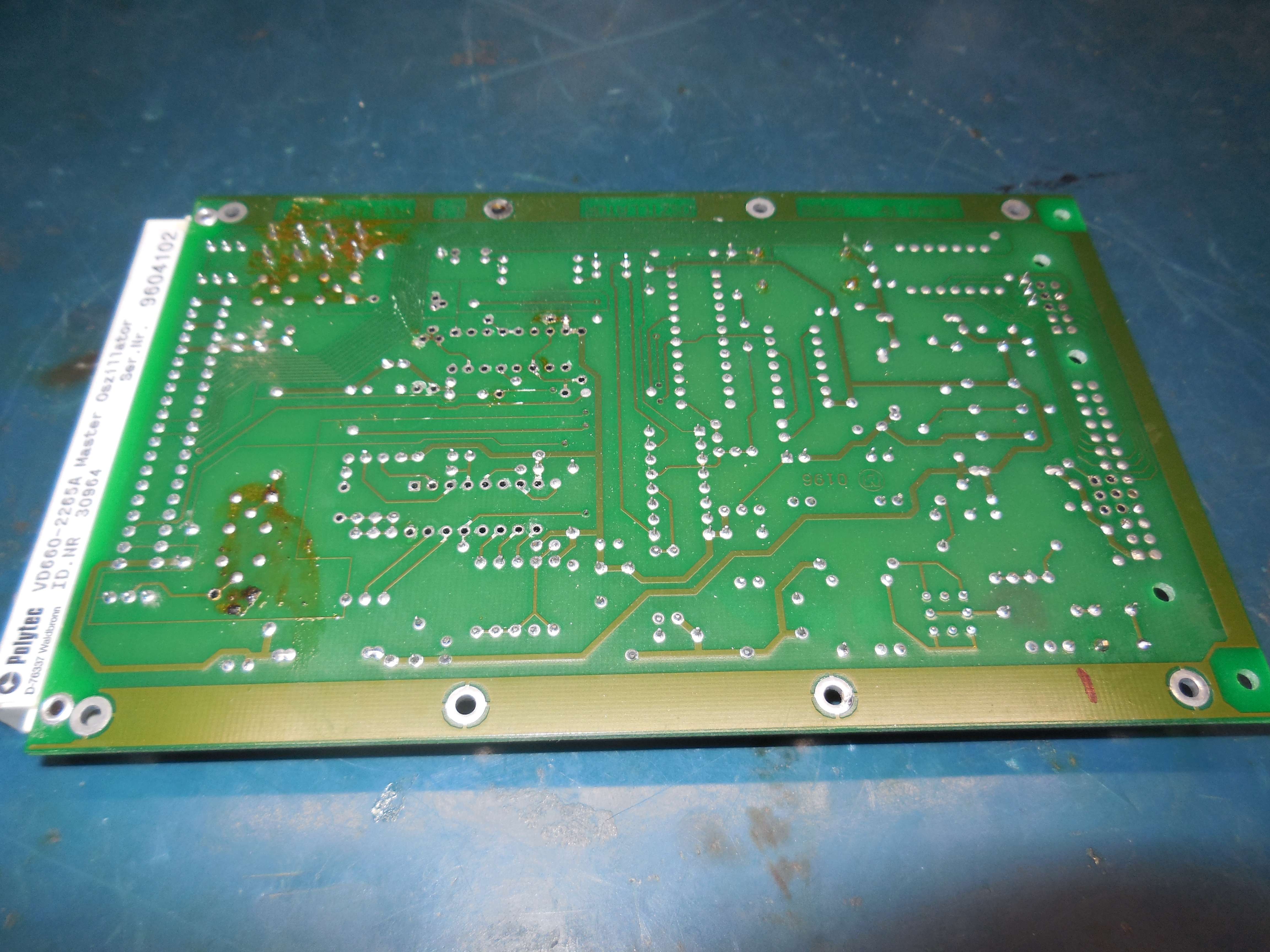
VD660-2265A Master Oscillator (39.831 MHz to Quadrature Demodulator Board?)
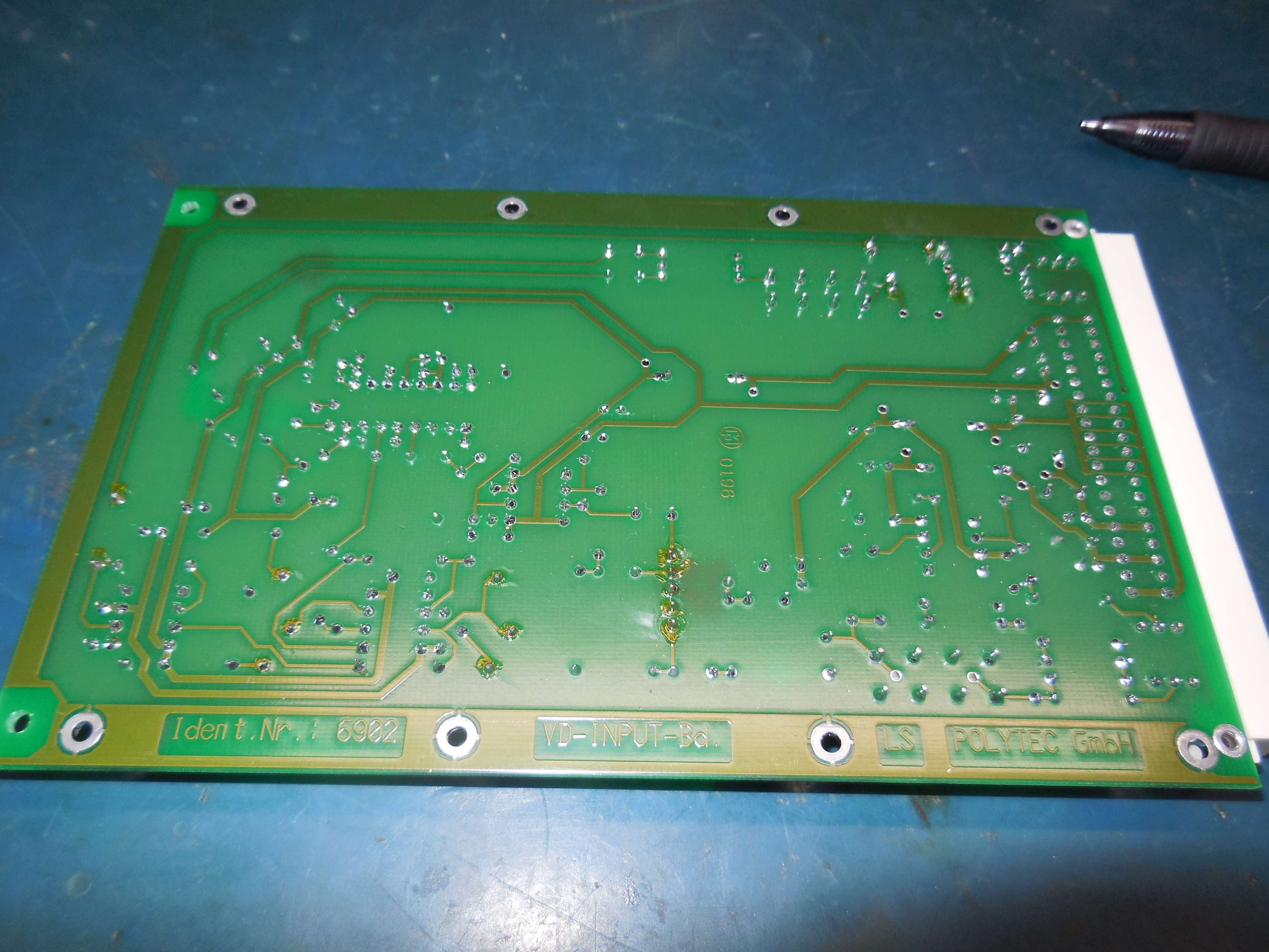
VD Input Board (Inside the Shielded Box)
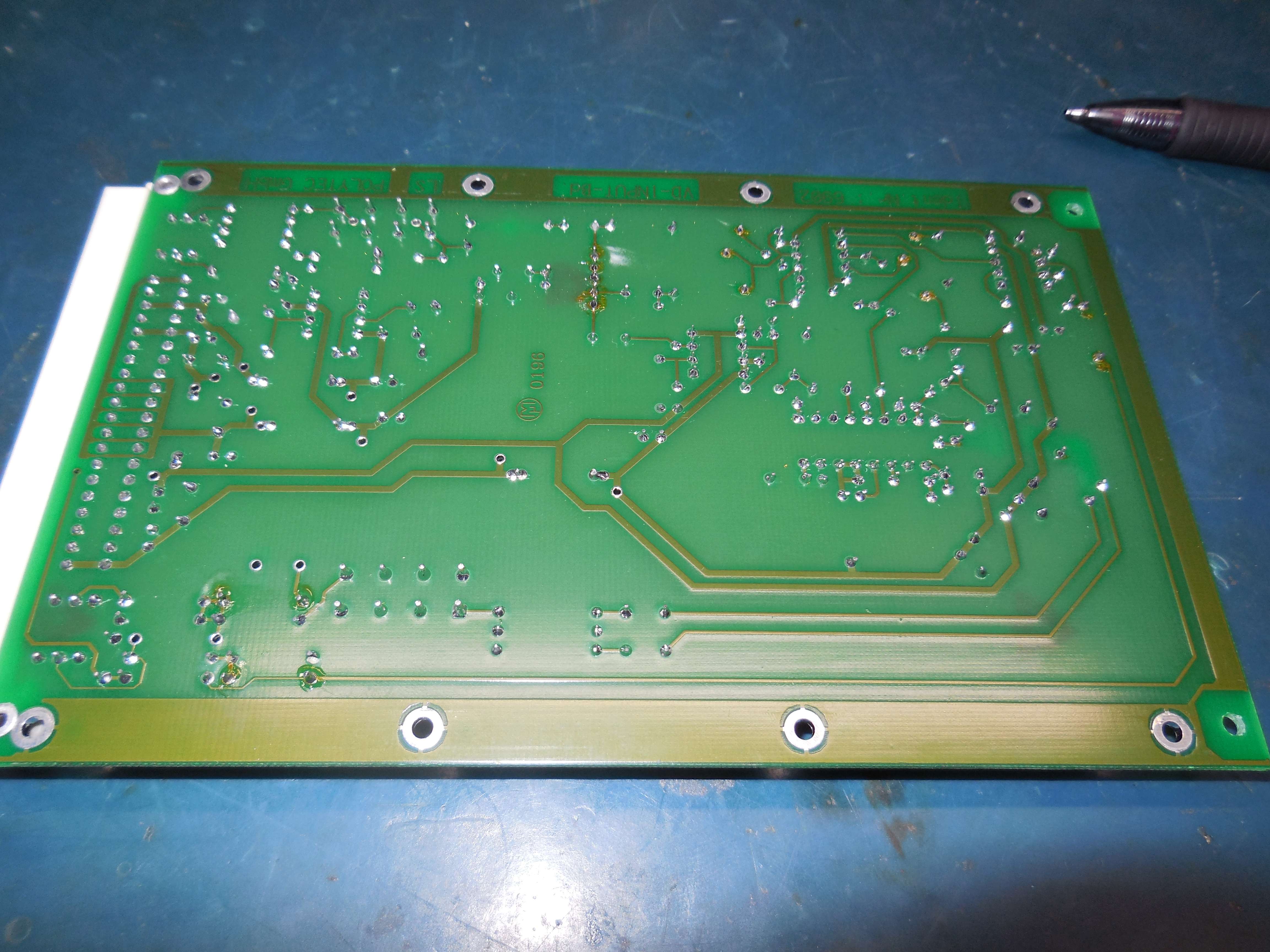
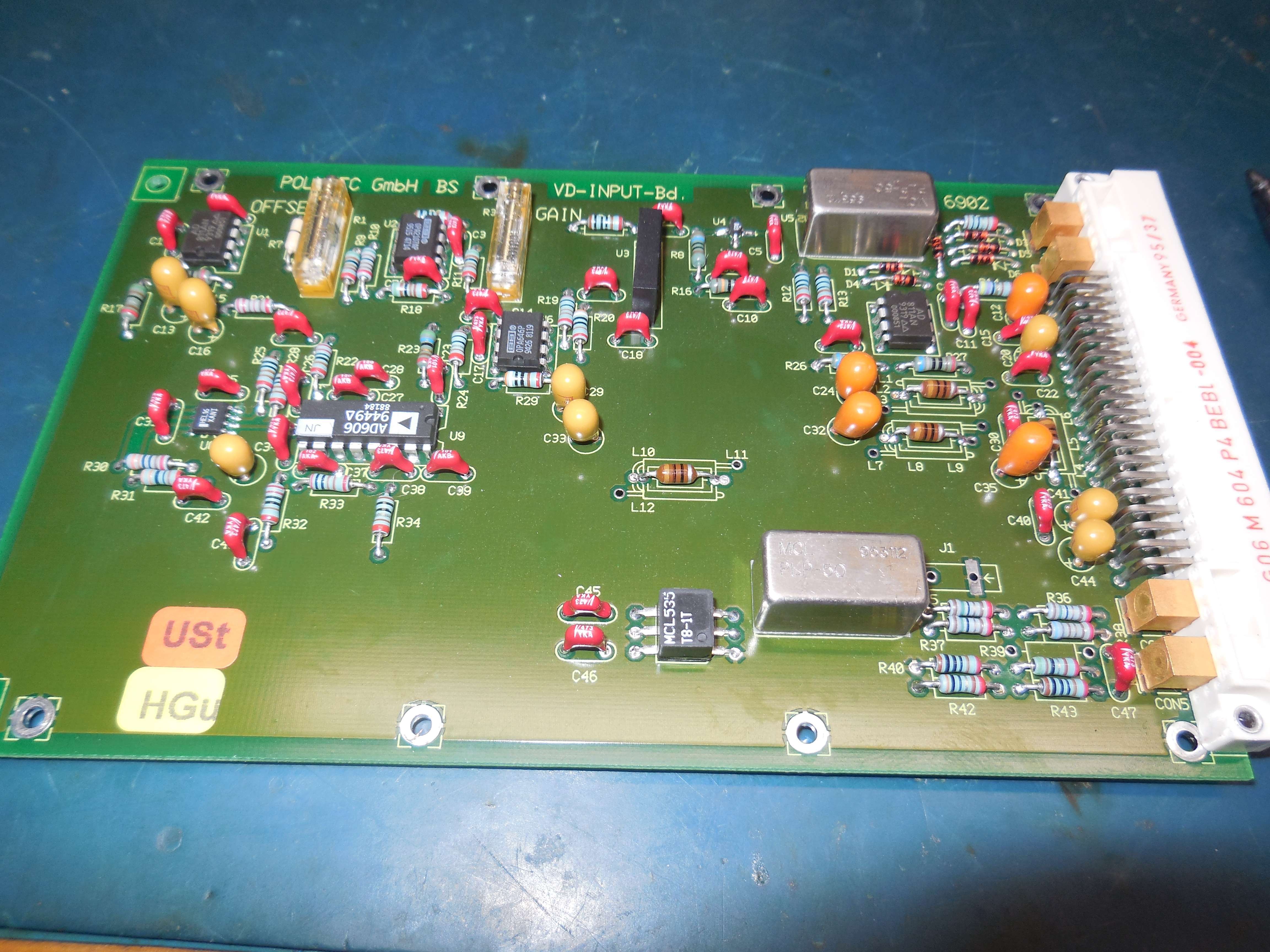
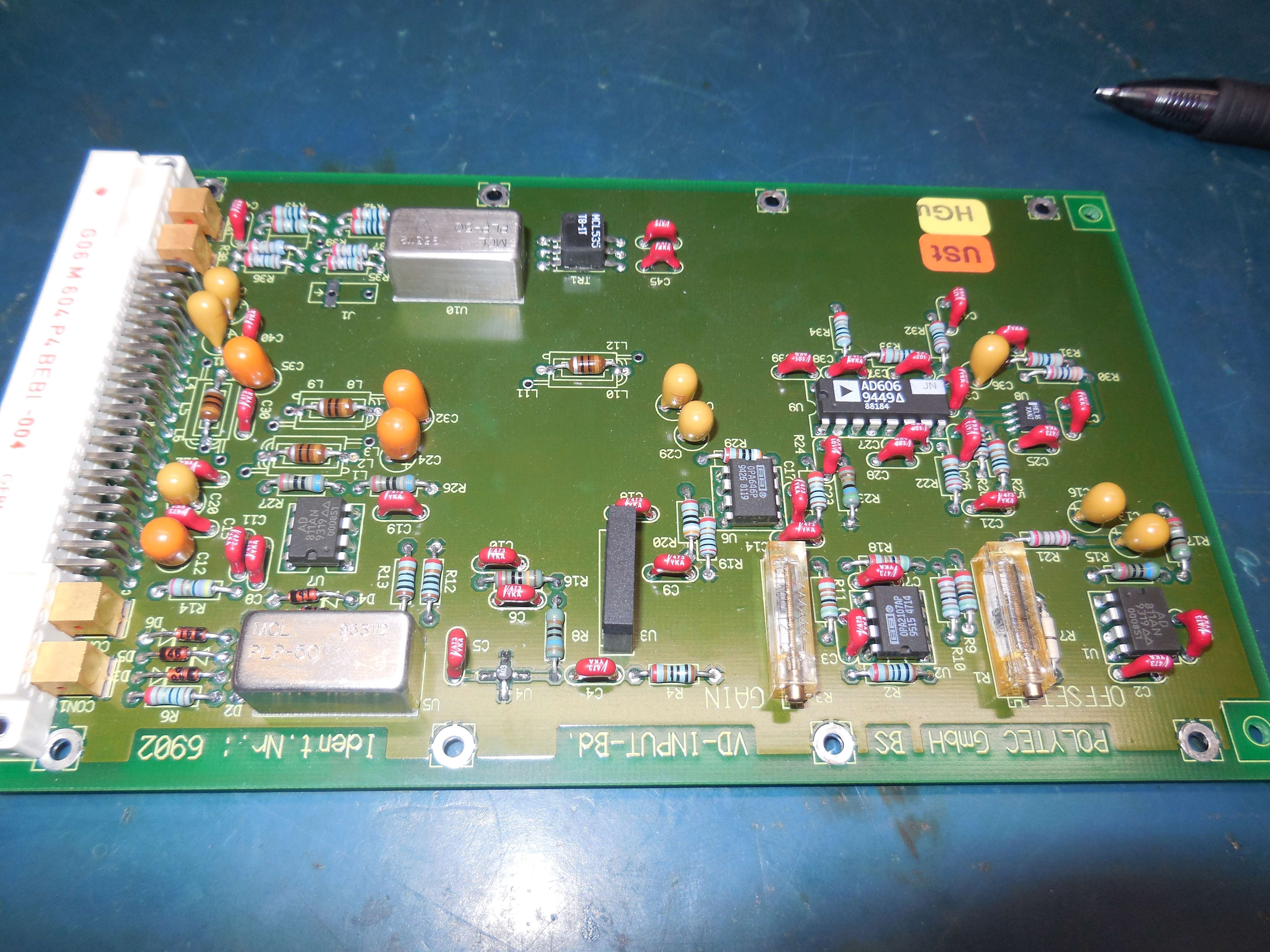
U3 is some type of resonator/filter/delay line: "S+M X.6960M KB/E2"
AD606, AD811, Motorola HEL16 (?), OPA2107, OPA646, MCL PLP-50 (50 MHz LPF), MCL T8-1T (Transformer), A03 (MCL MAR-3)
DFE-650 Mainboard
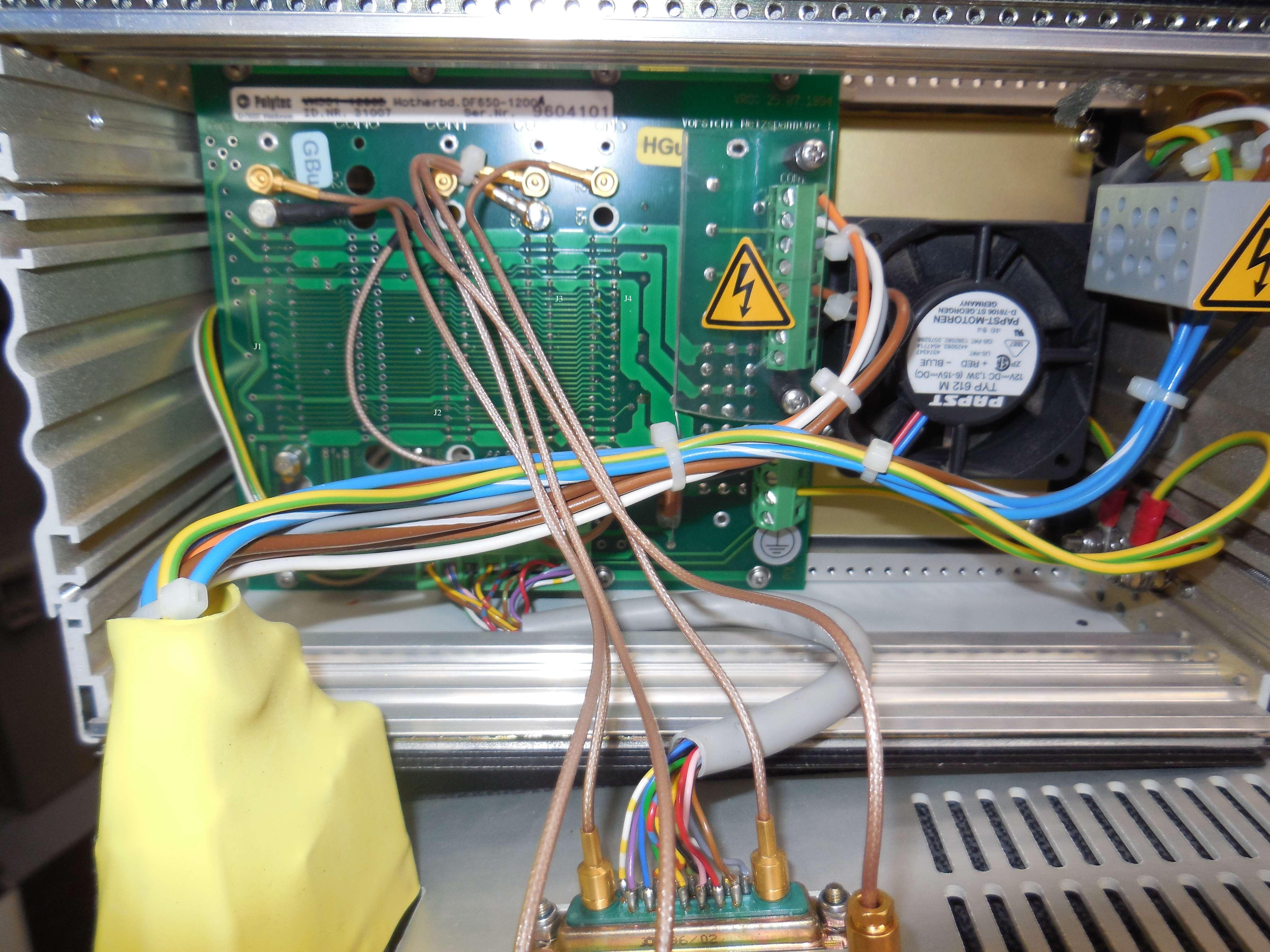

Rear-View: J1 is on the left. Front-View: J1 is on the right.
- J1: DFE-0650-INP1A Input Board (Takes up two slots, technically.)
- J2: VD660-2265A Master Oscillator (39.831 MHz)
- J3: DFE-0650-QD11A Quadrature Demodulator
- J4: VM265-2265A Master Oscillator (80 MHz)
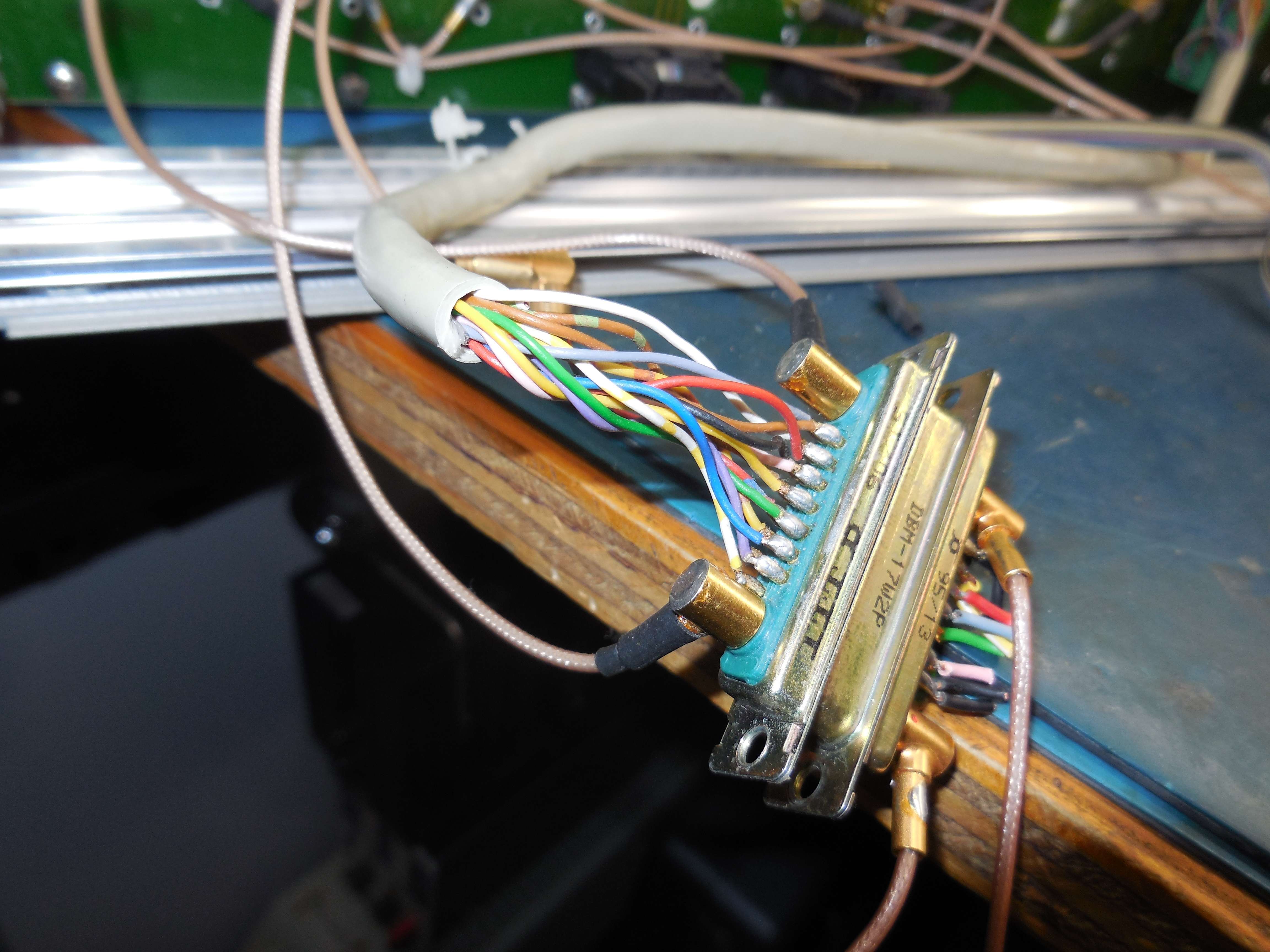
DBM-17W2S Pin-Out "Green Panel" Pin Description 1 Brown 1 Ground 2 Red 7 +5 VDC 3 Pink 2 +16 VDC 4 Yellow 1 Ground 5 Green 3 -15 VDC 6 Blue 2 +16 VDC 7 Violet 8 Ground 8 Grey 8 Ground 9 White 2 +16 VDC 10 Black 3 -15 VDC 11 Brown w/ Green 6 12 Red w/ Blue 5 Signal Level 13 Yellow w/ Brown 4 -5.2 VDC 14 No Connection 15 White w/ Yellow 8 Ground A1 Coaxial: Signal Input or 80 MHz Bragg Out A2 Coaxial: Signal Input or 80 MHz Bragg Out |
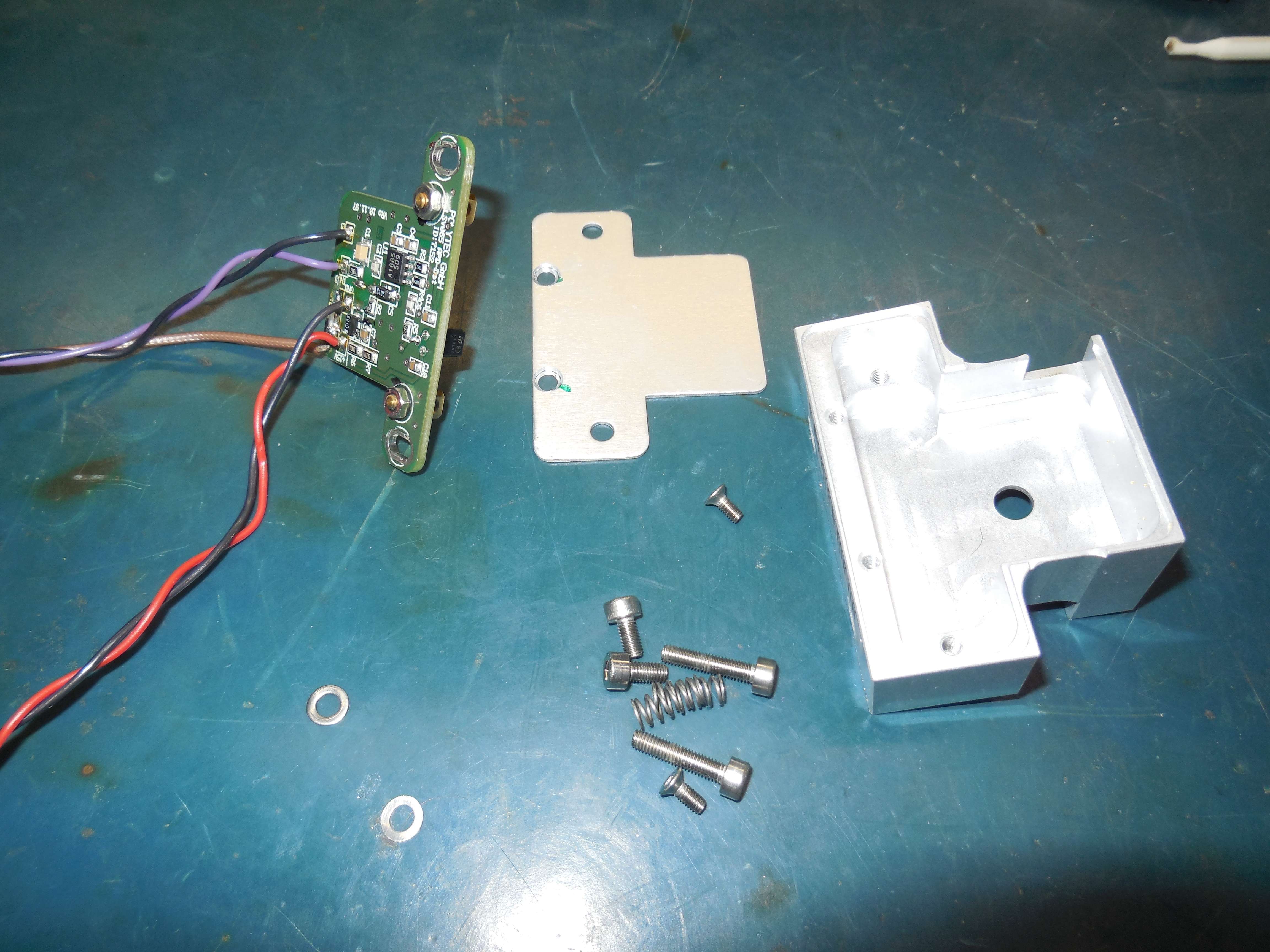
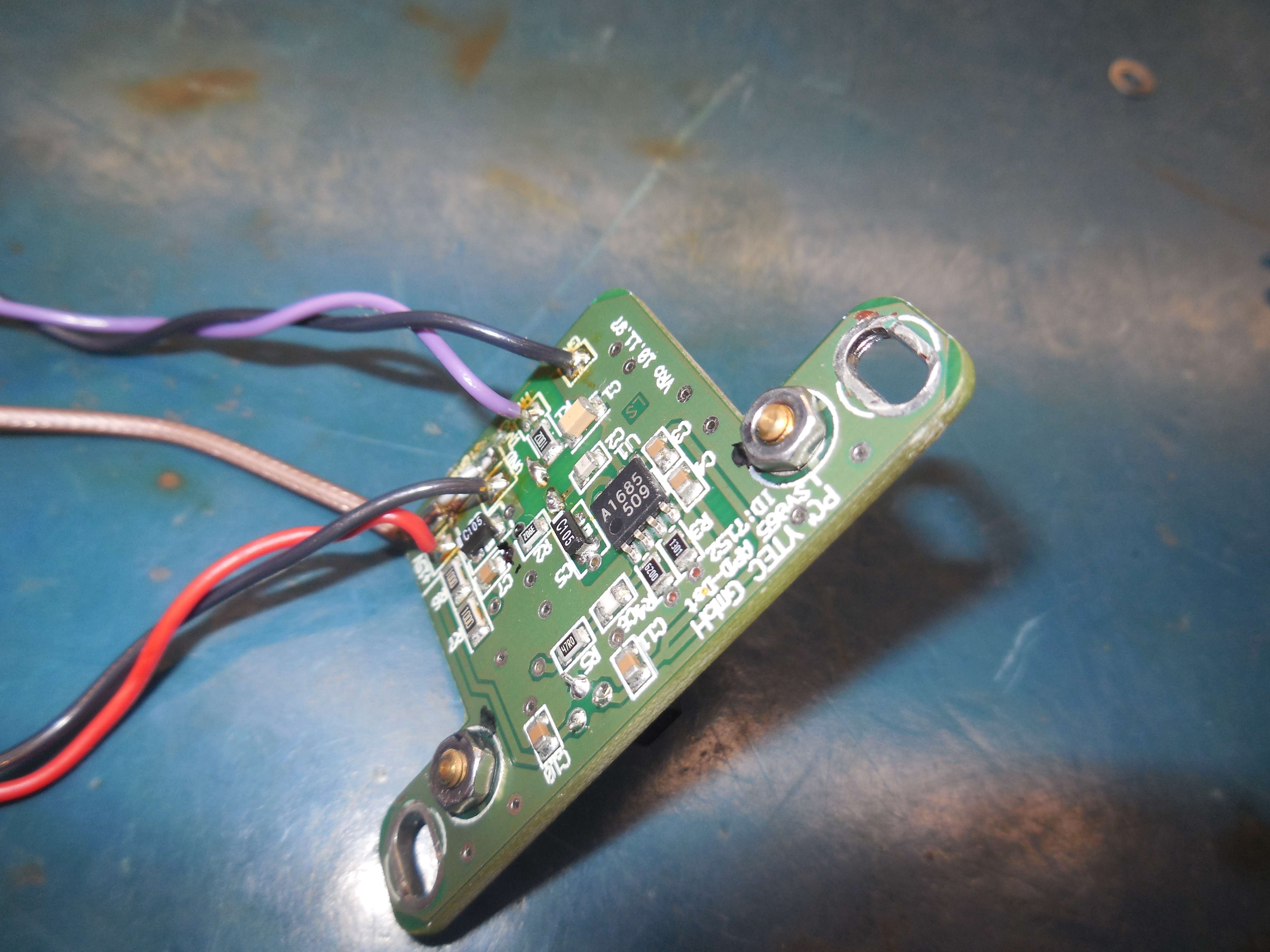
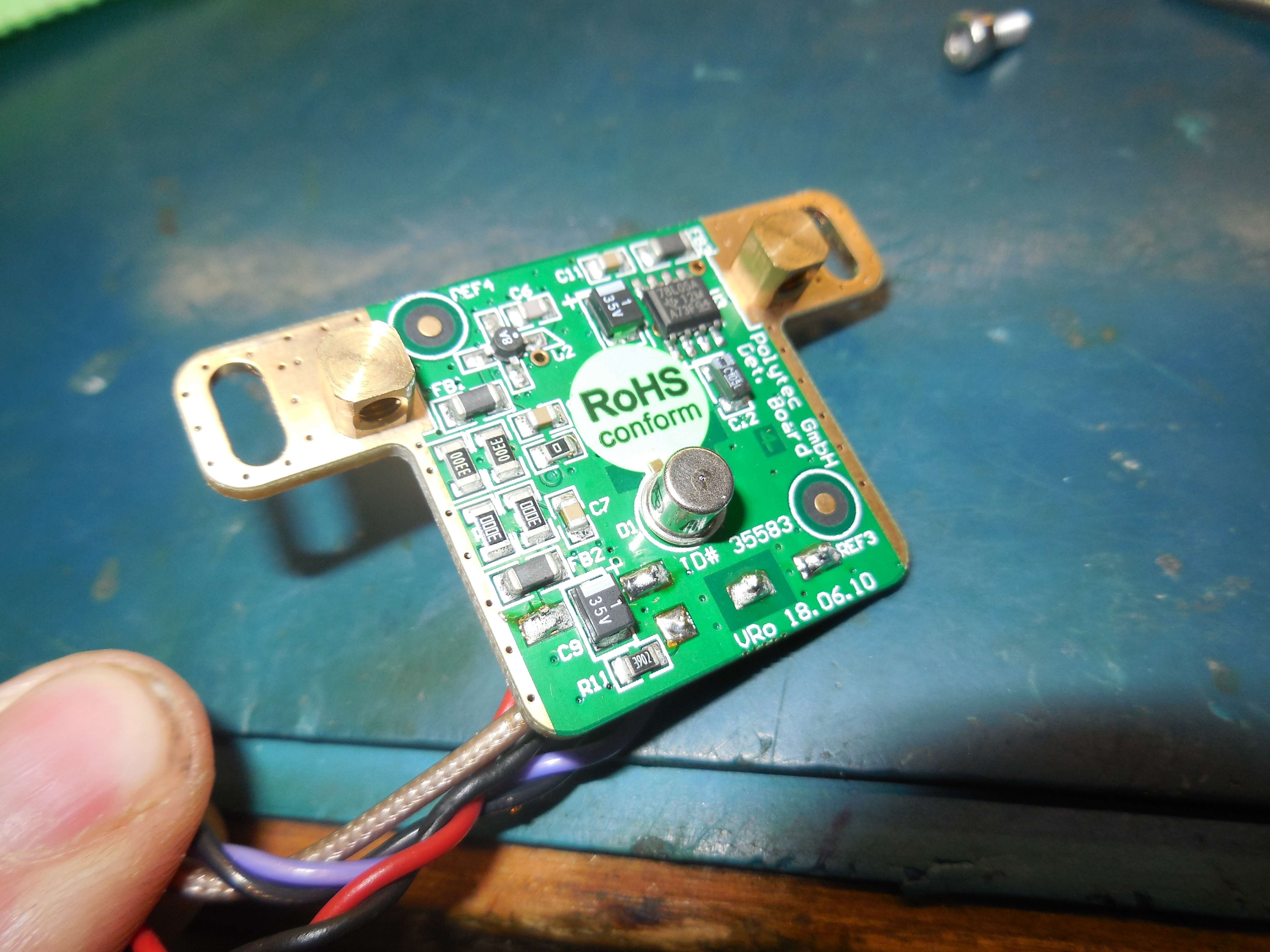
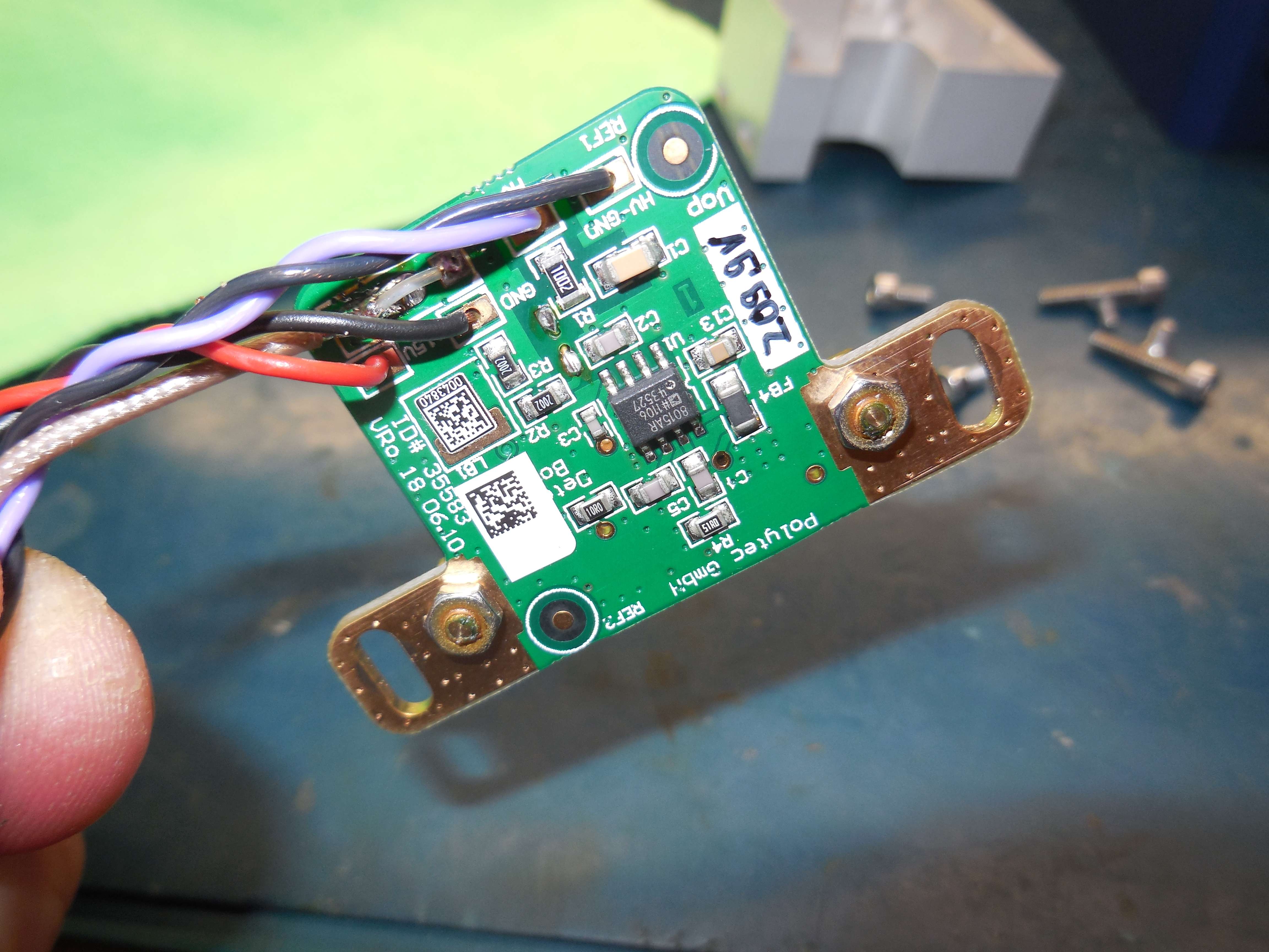
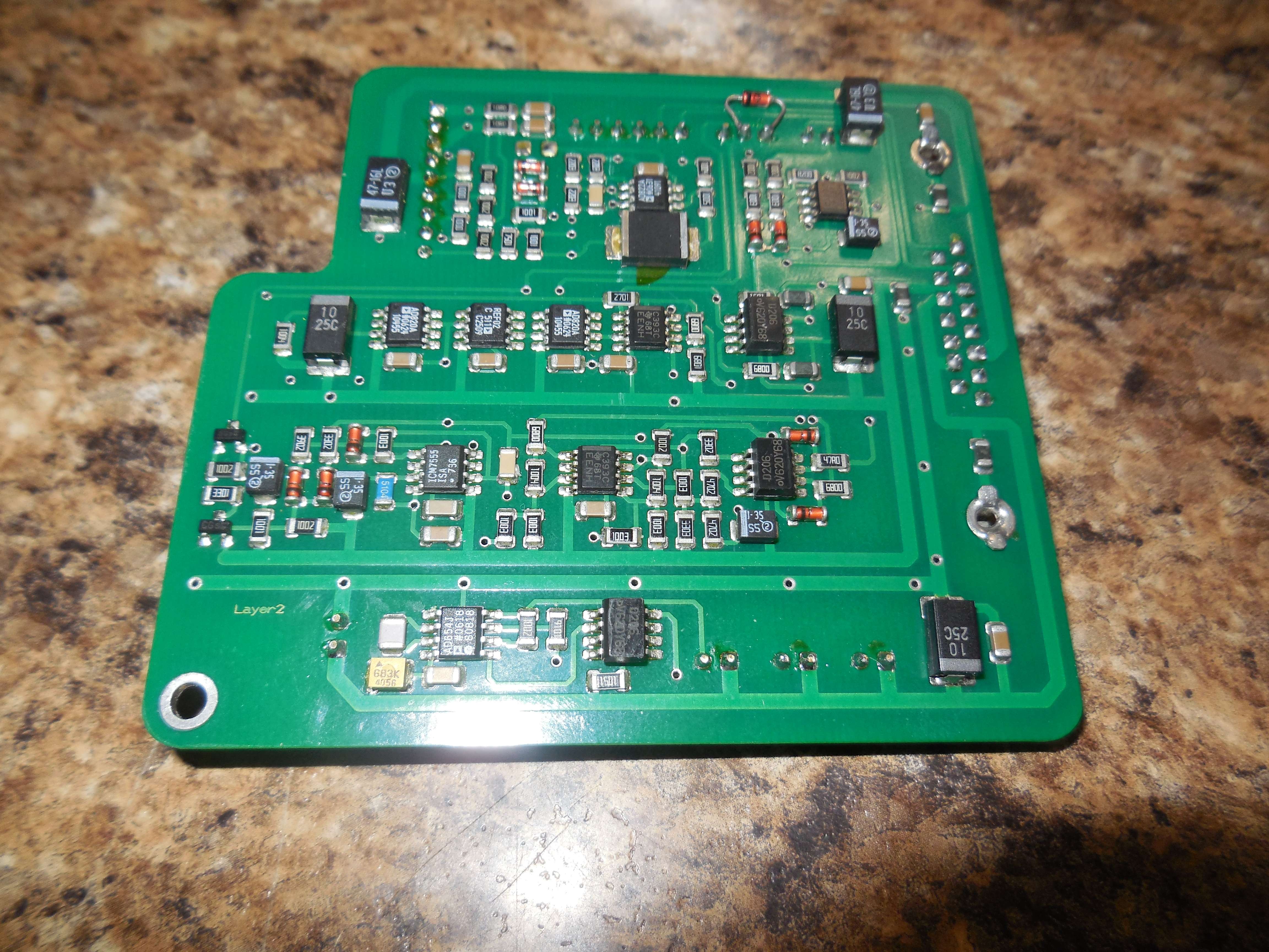
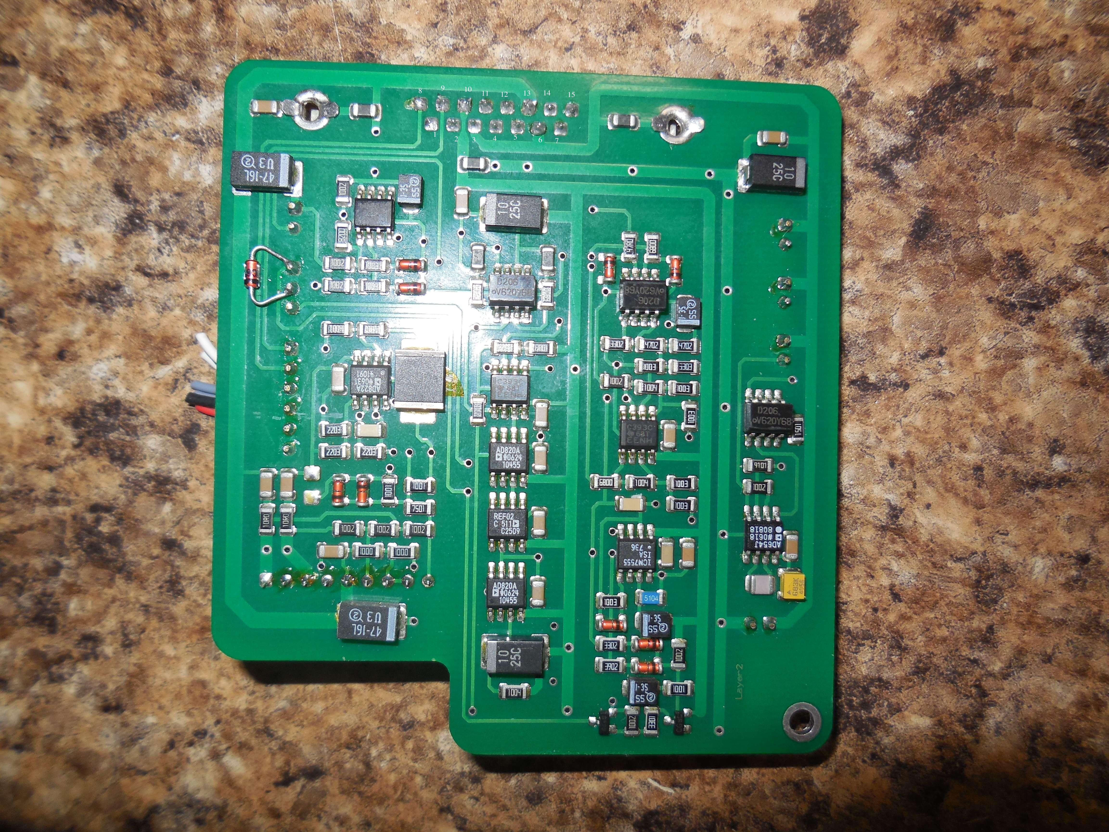
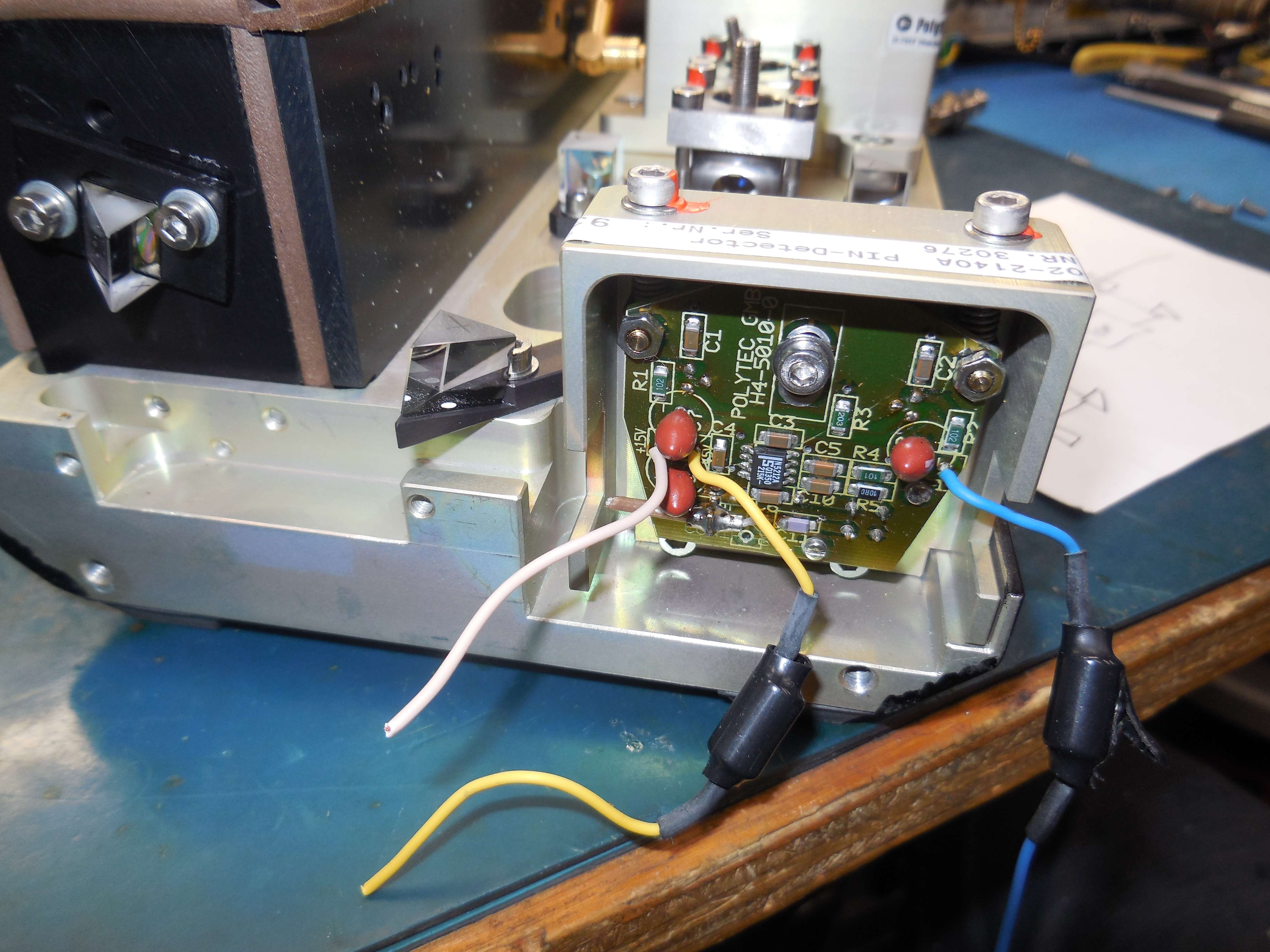
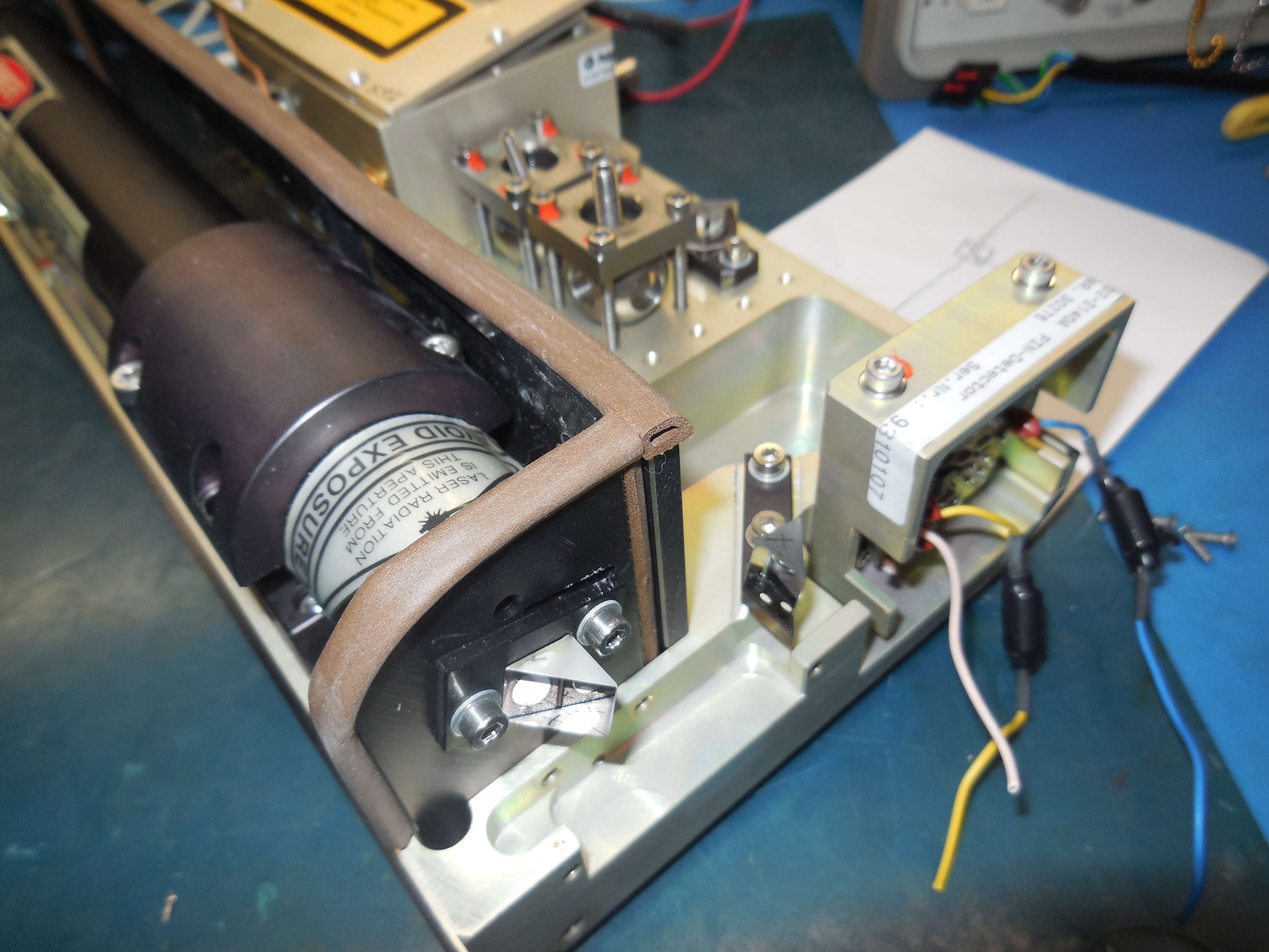
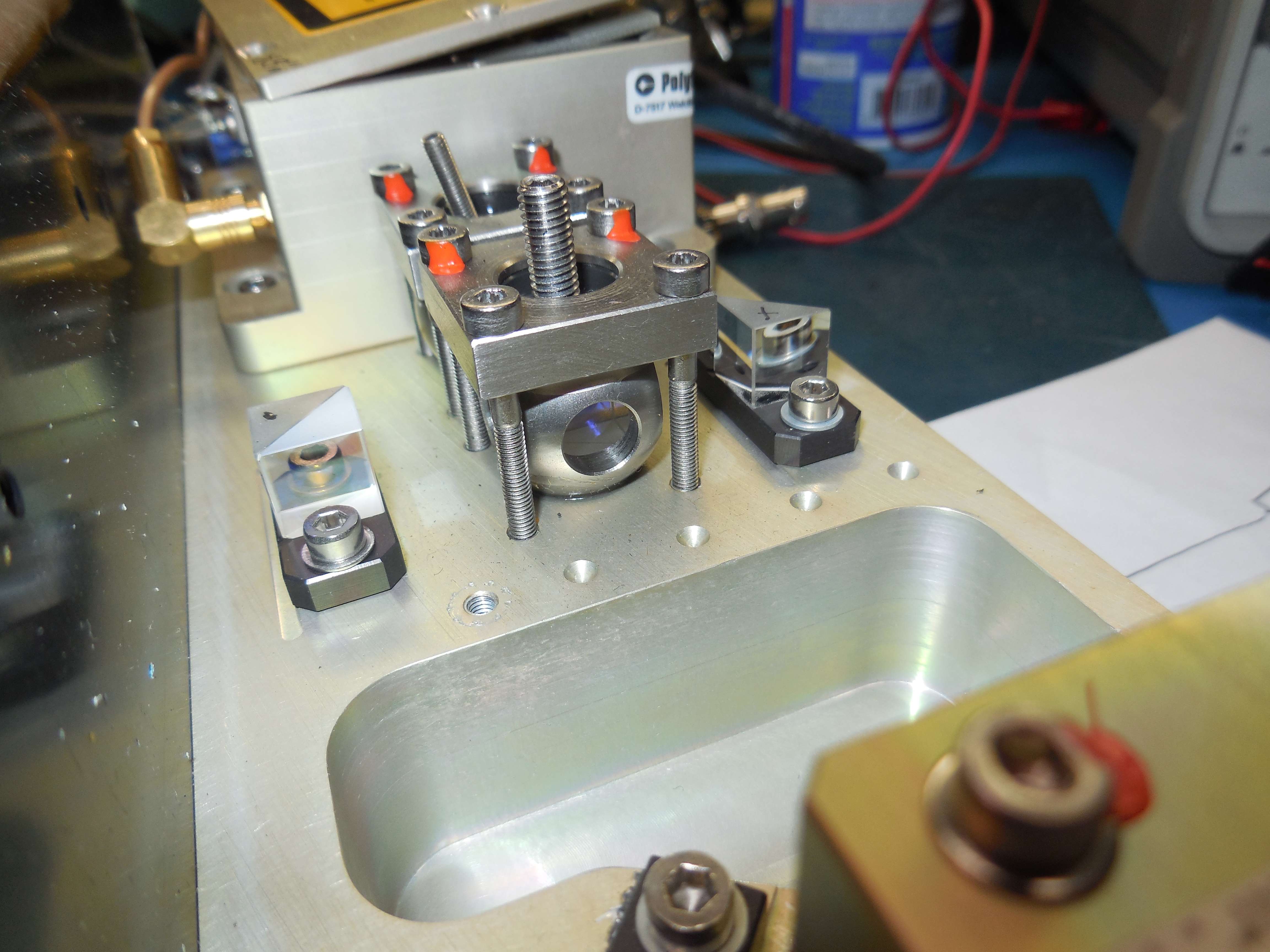
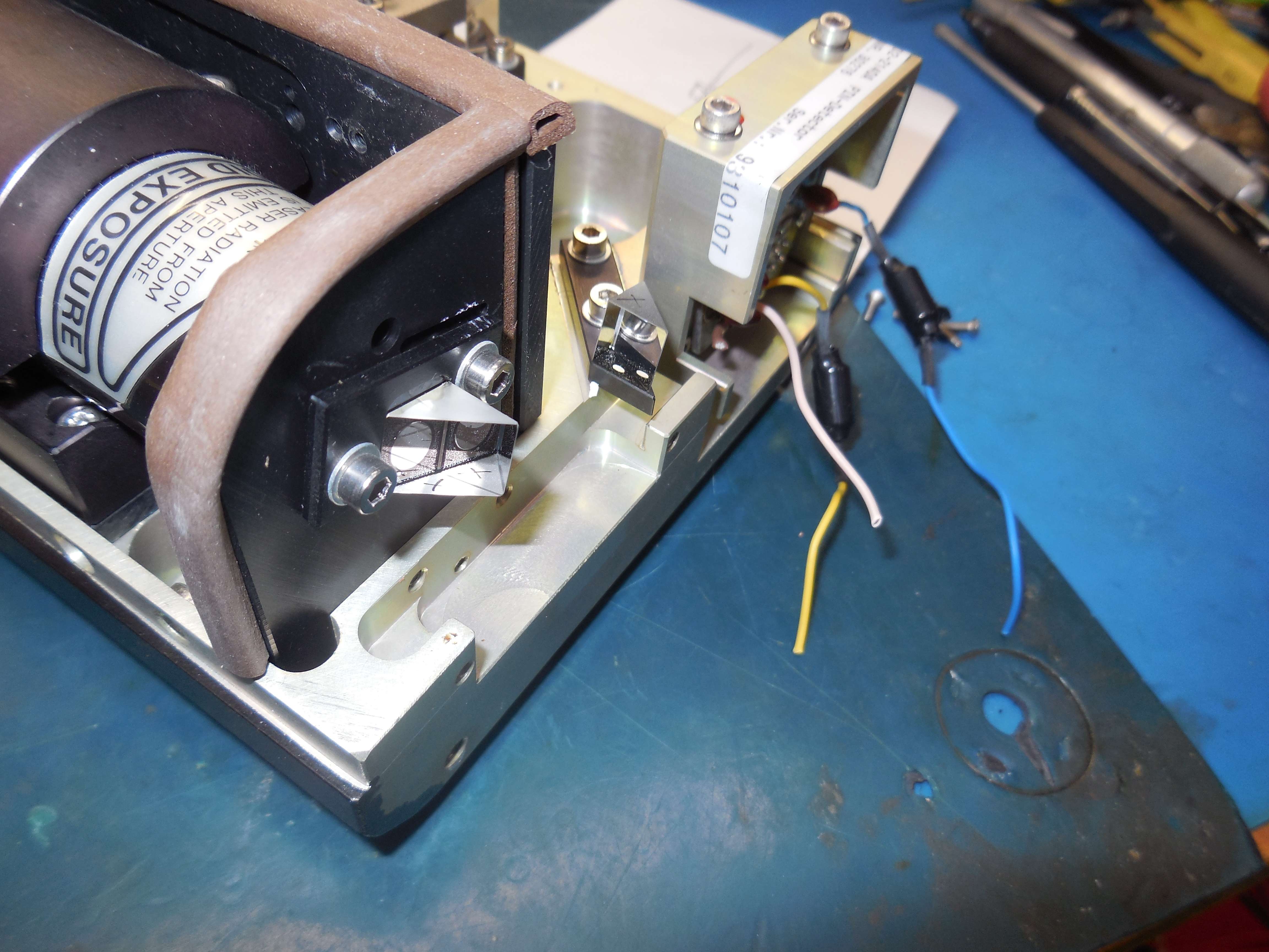
LSV-065 Linear Surface Velocimeter
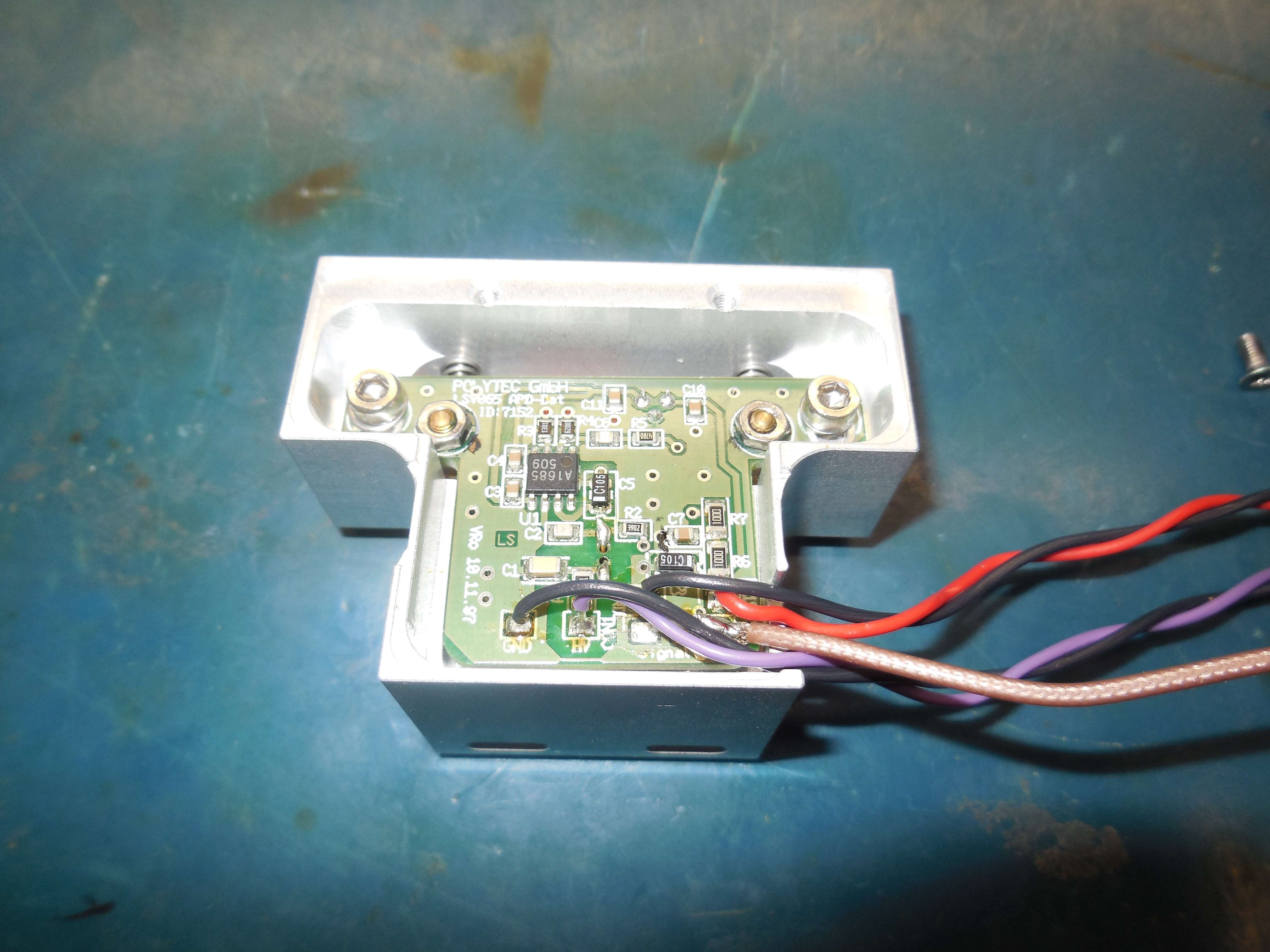
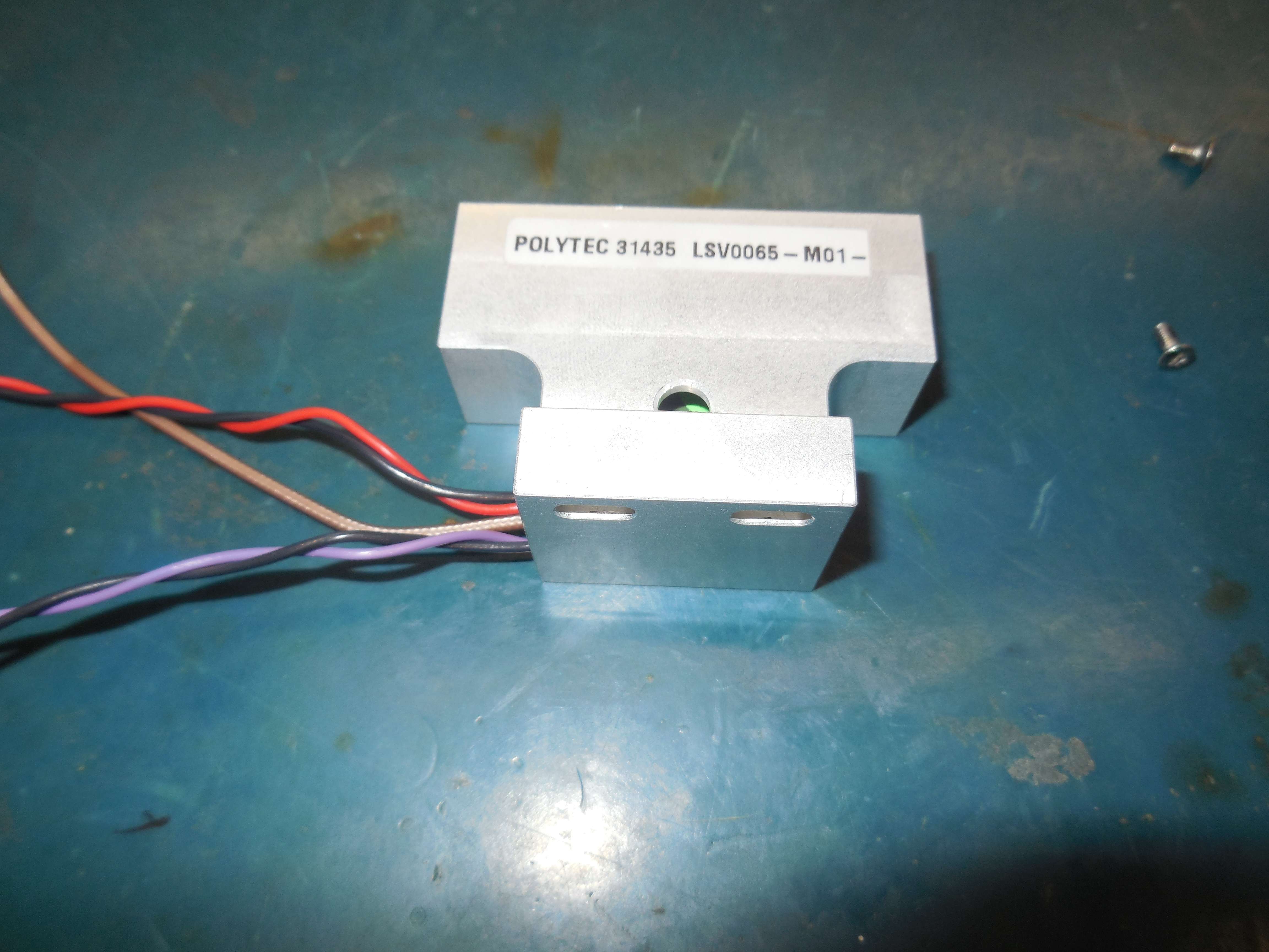

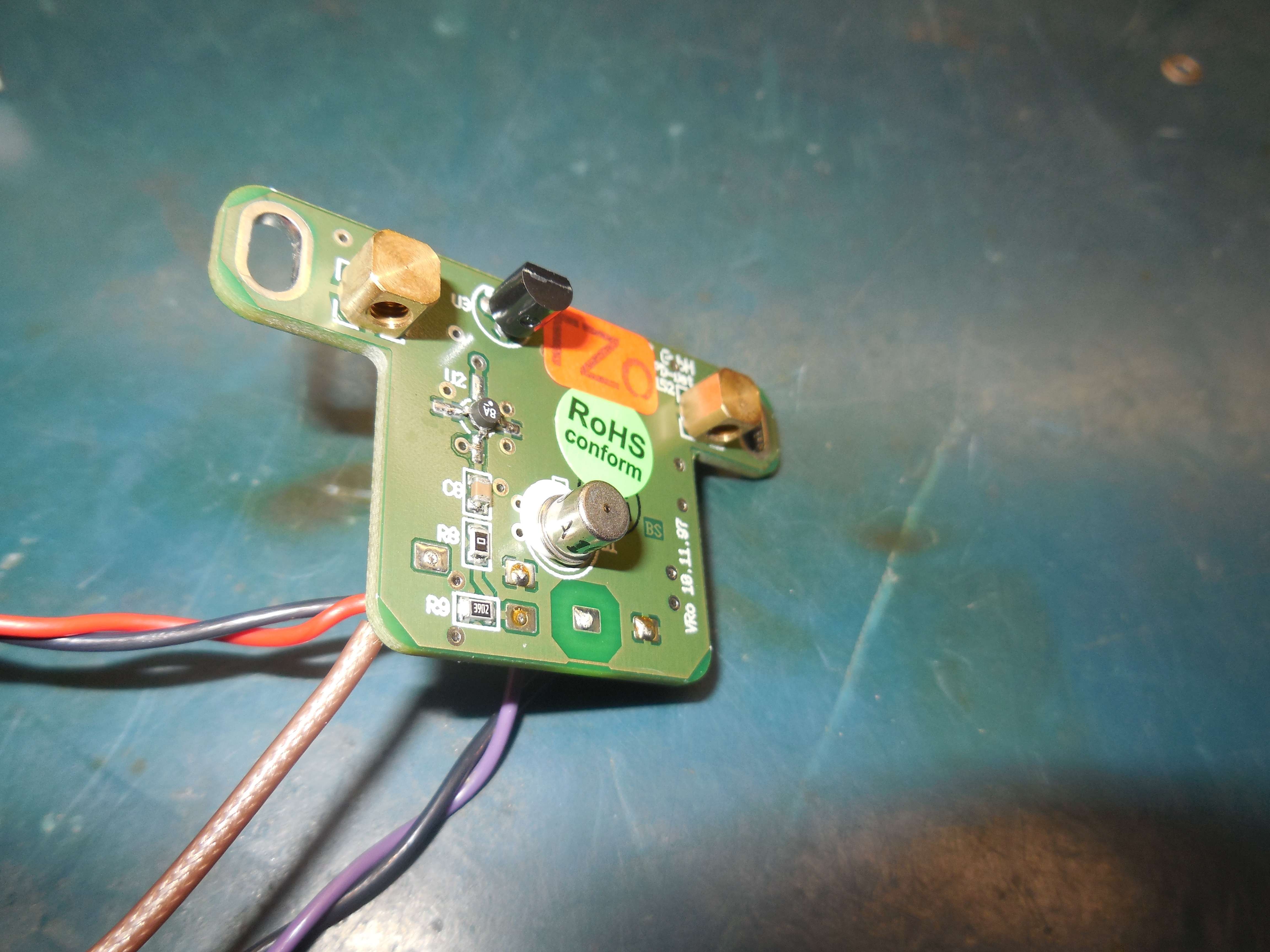
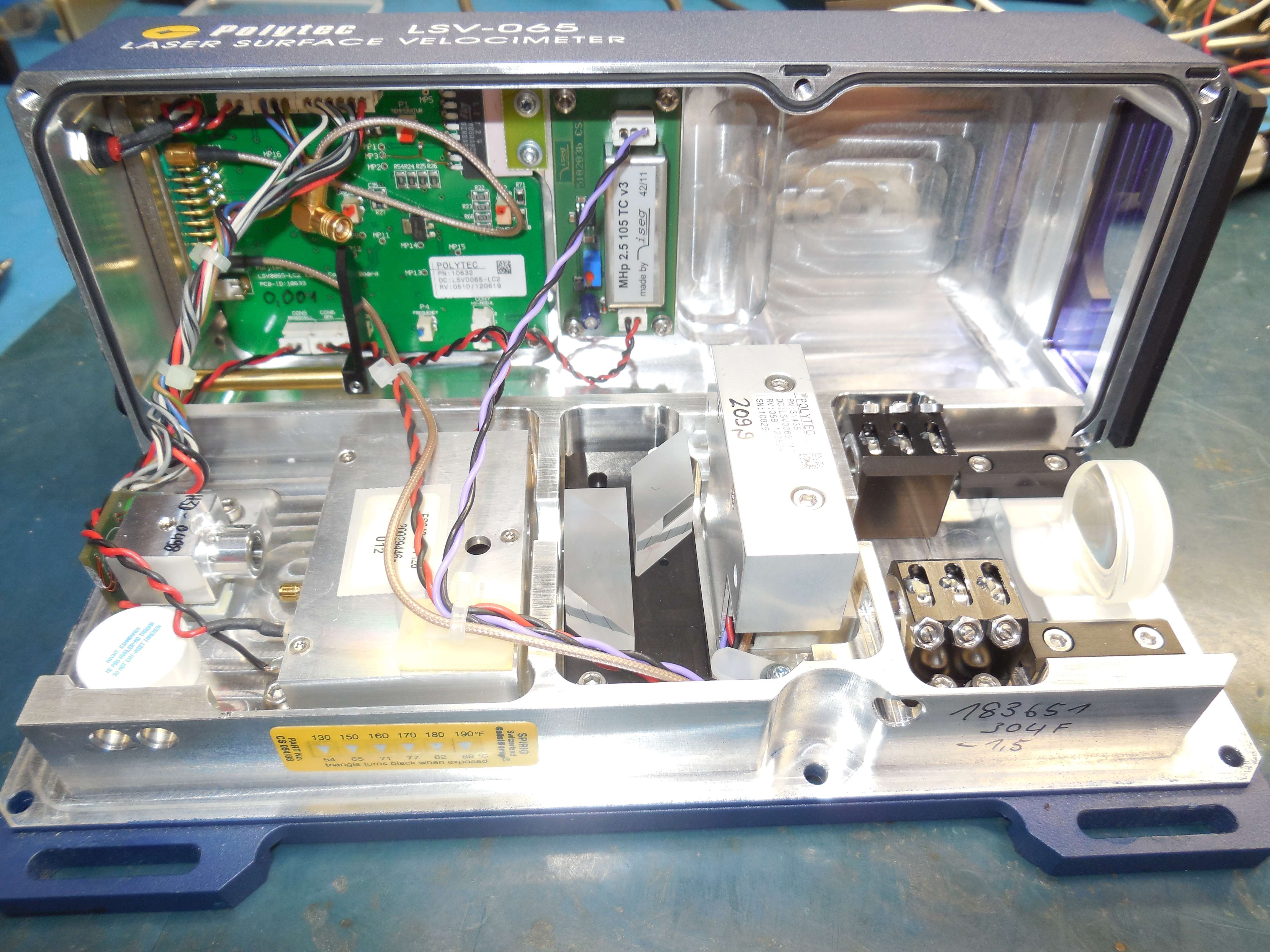
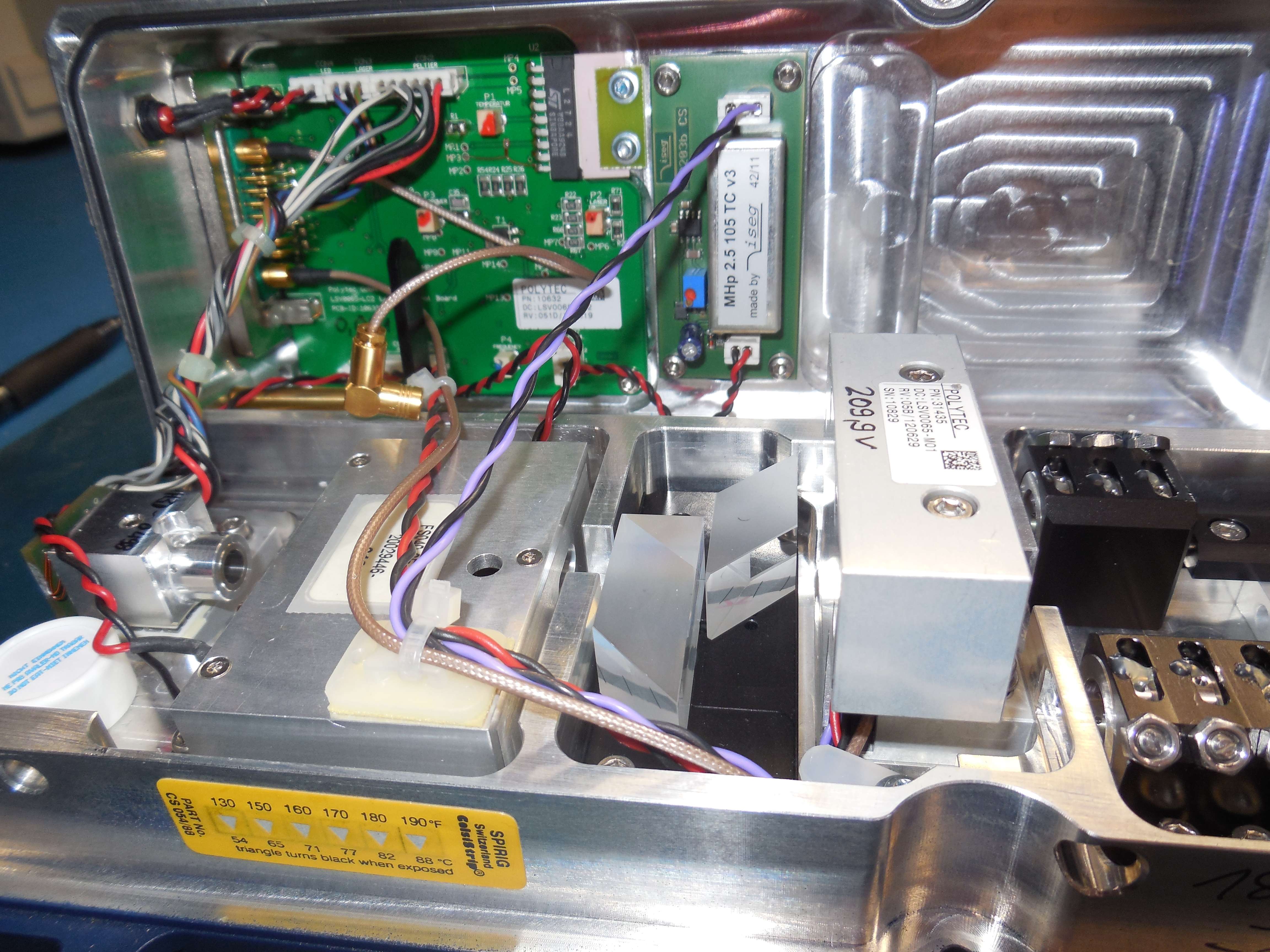
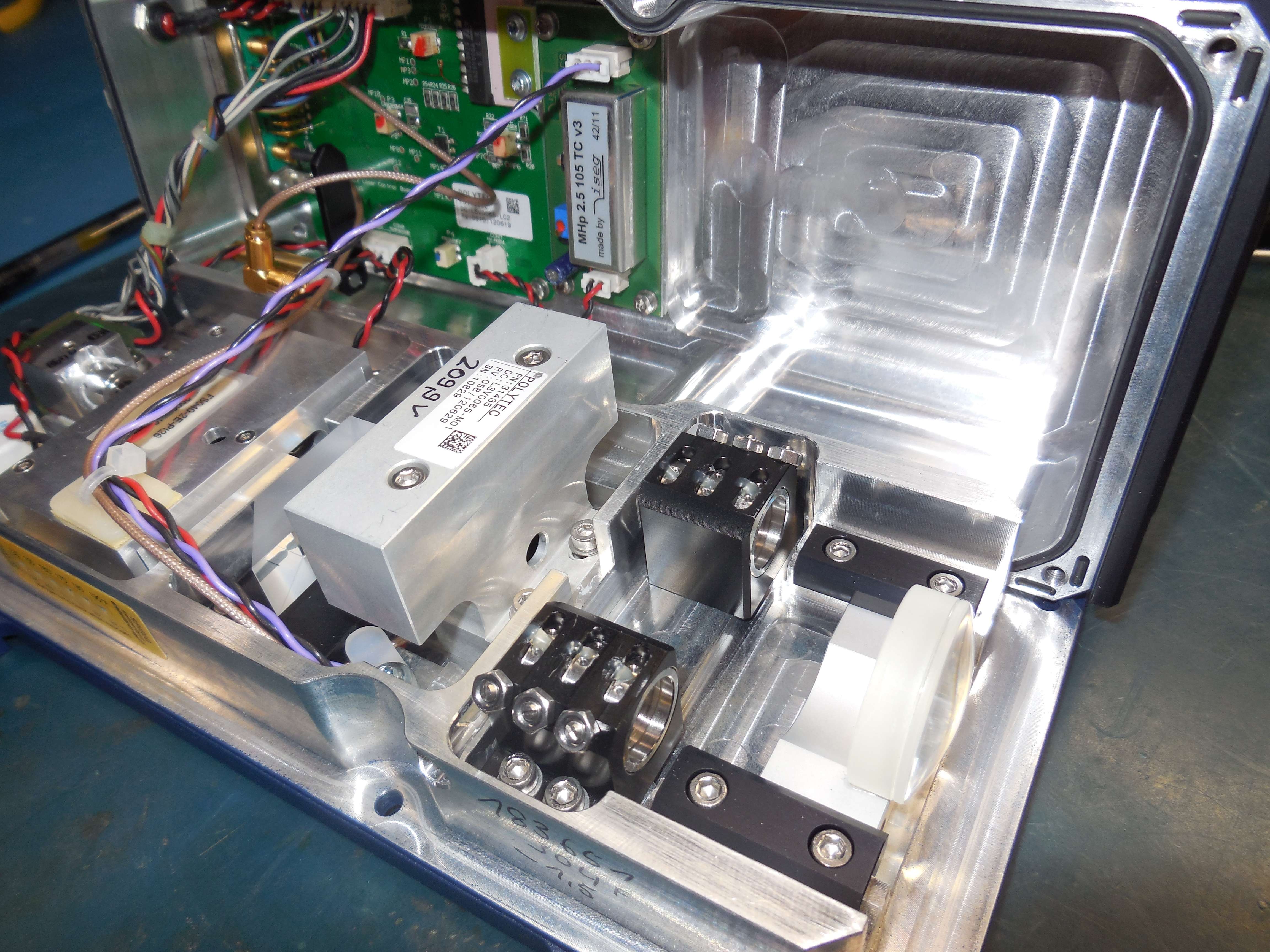
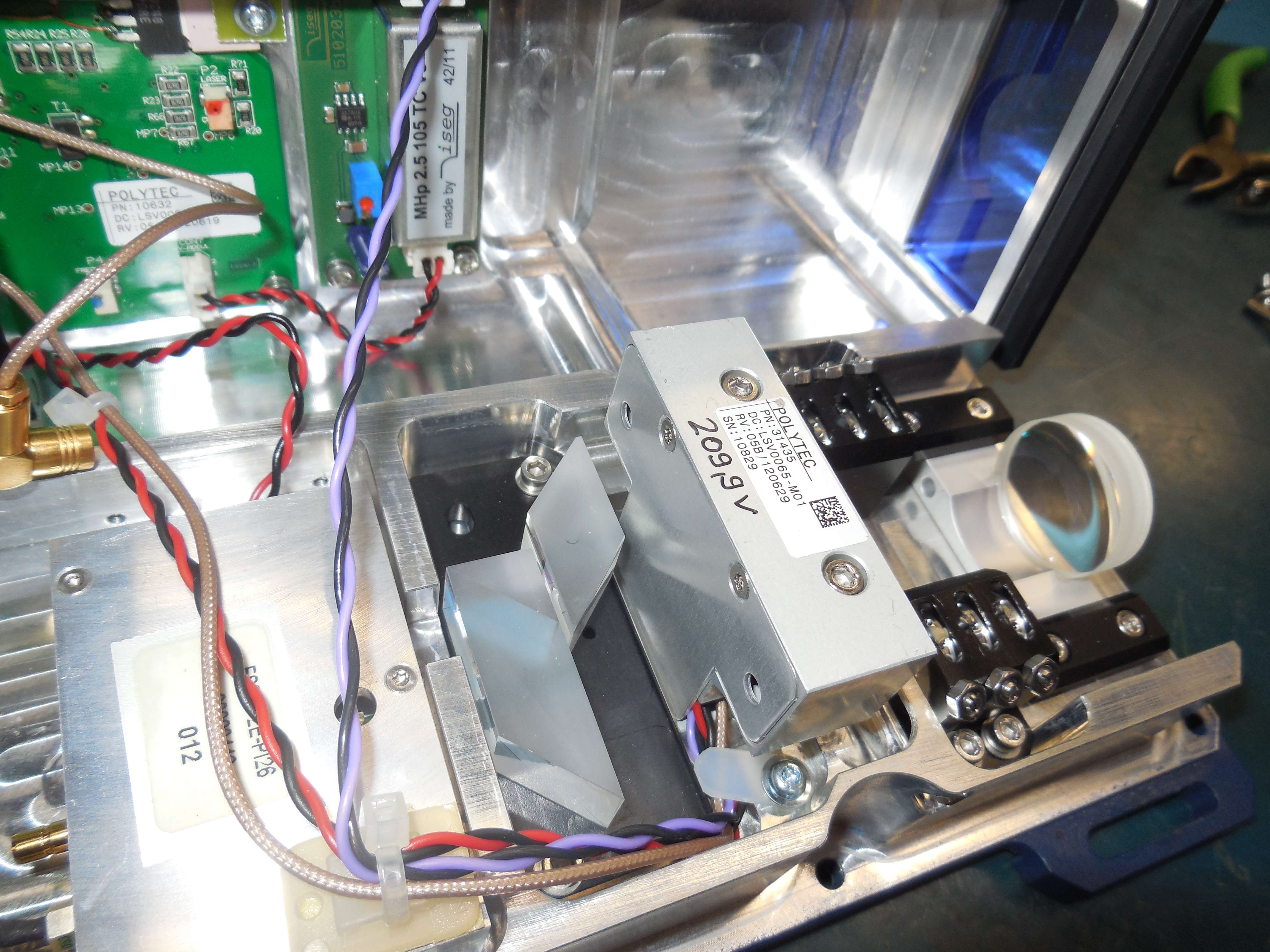
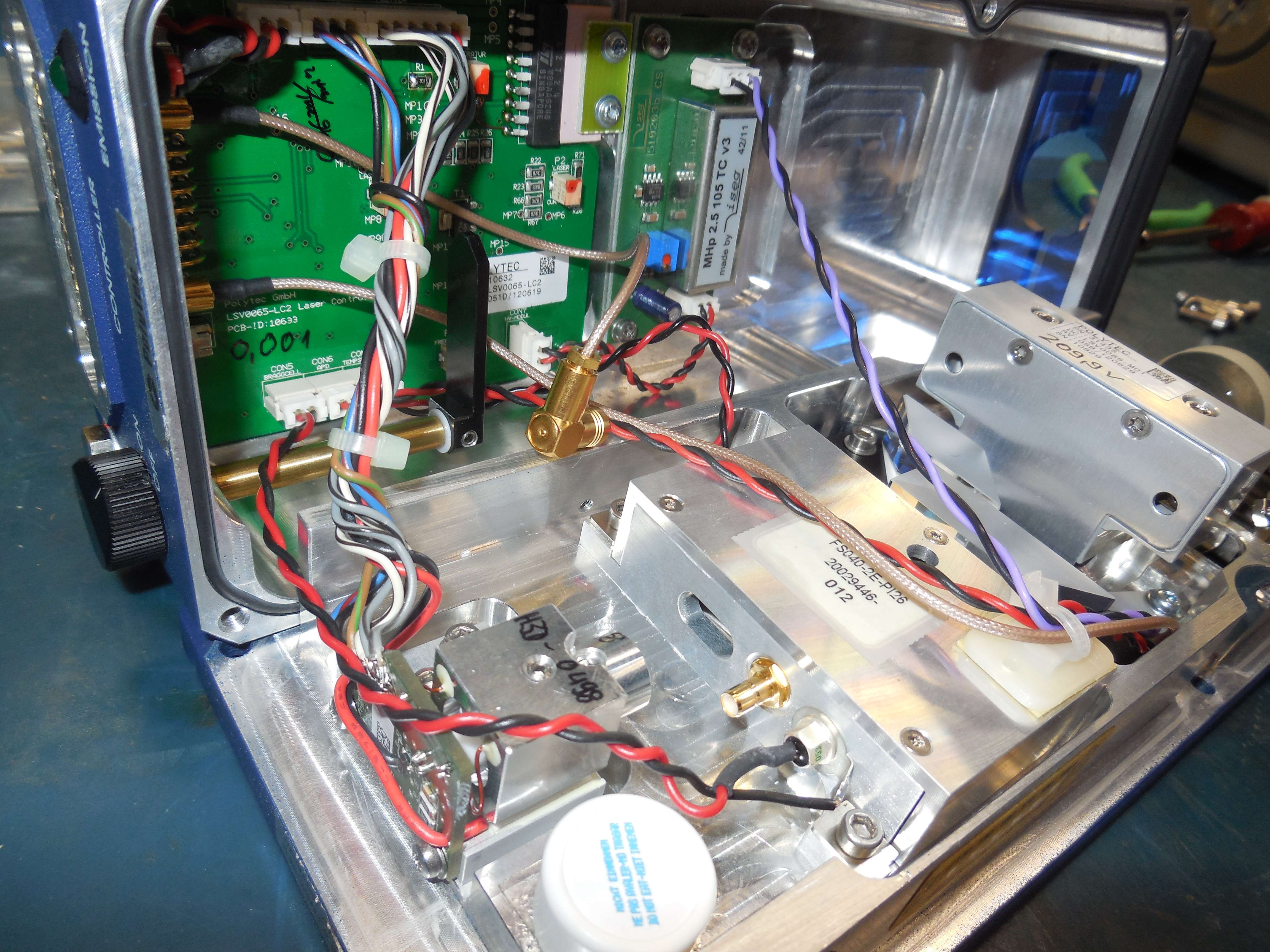
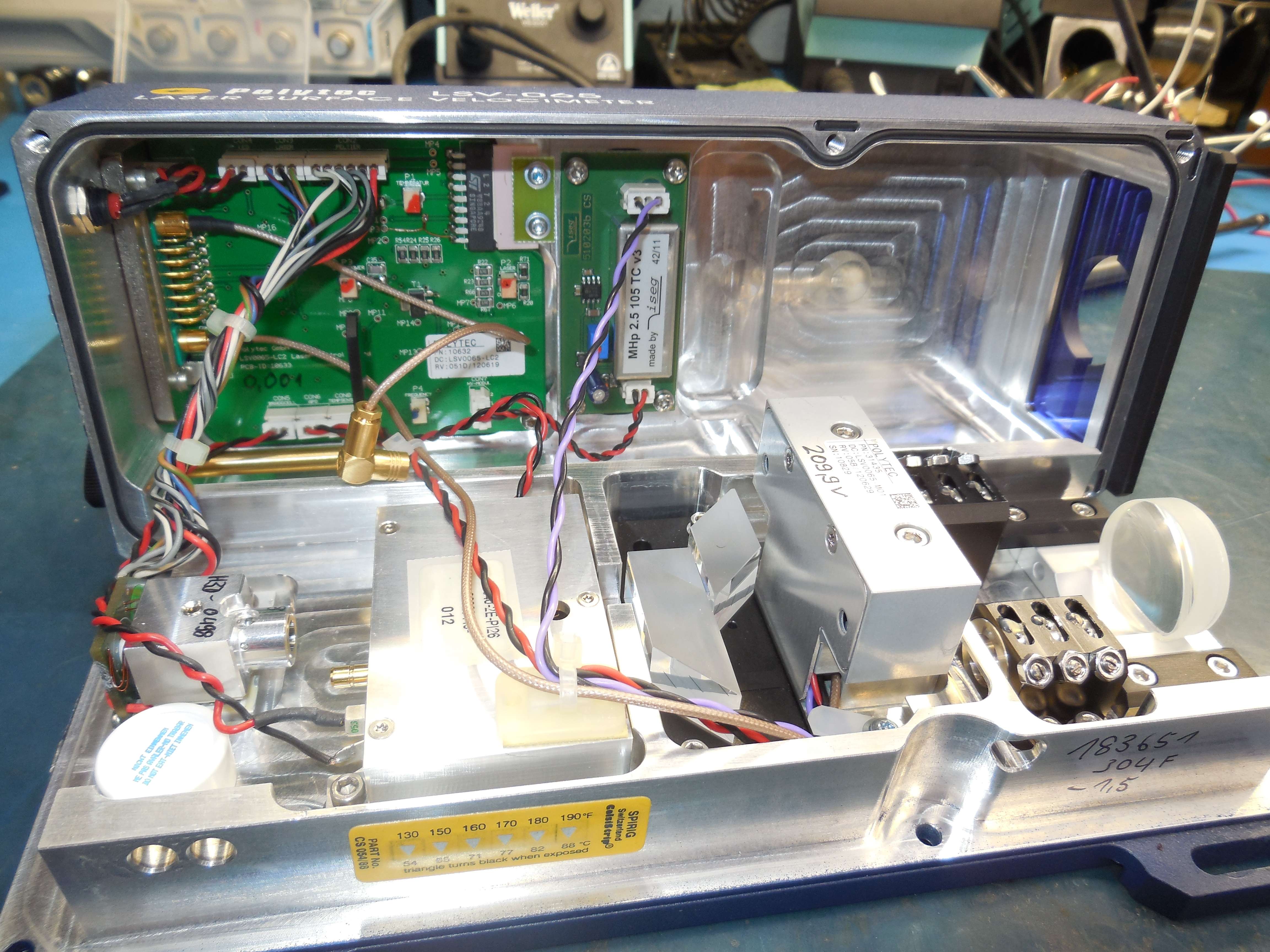
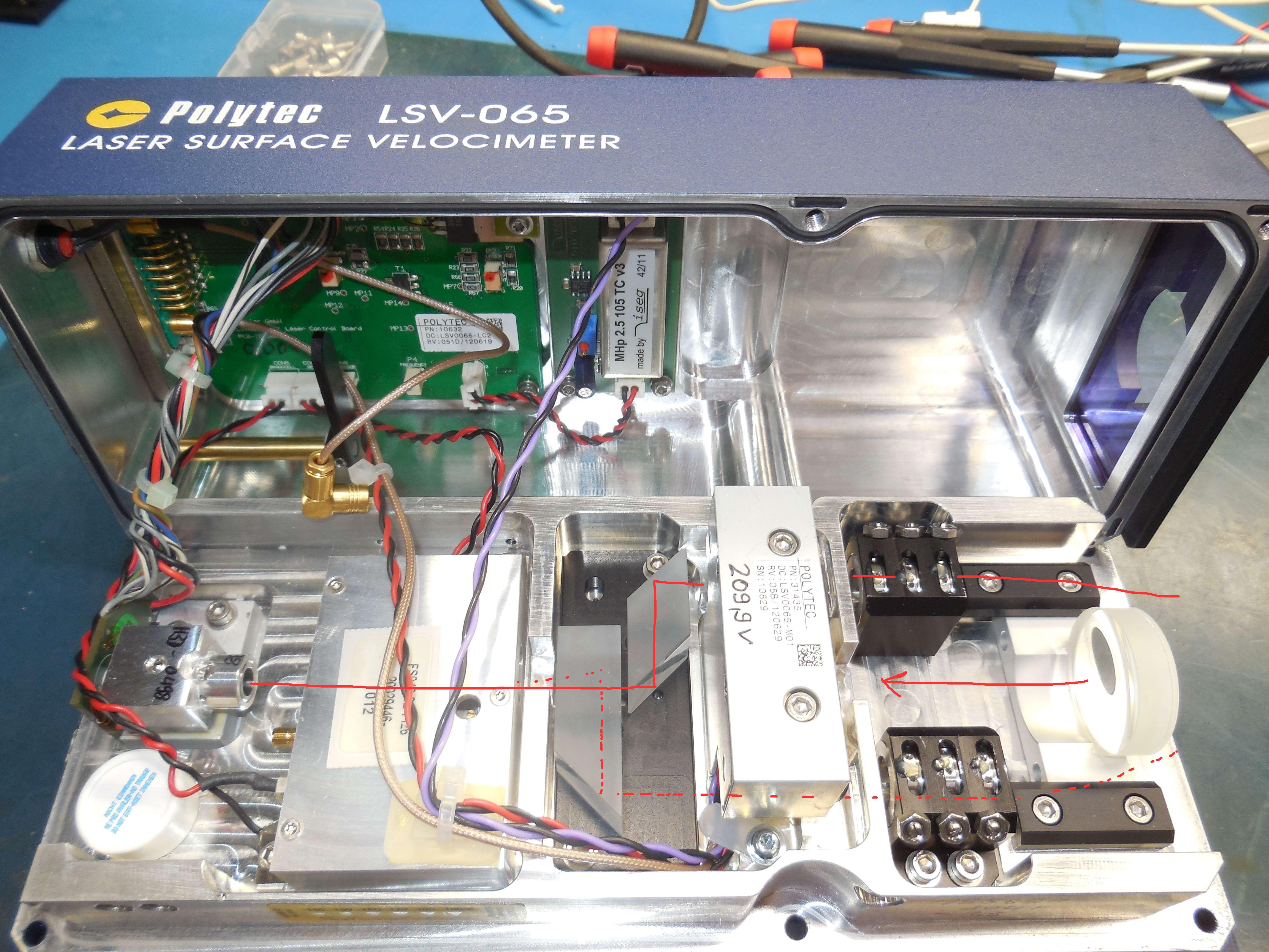
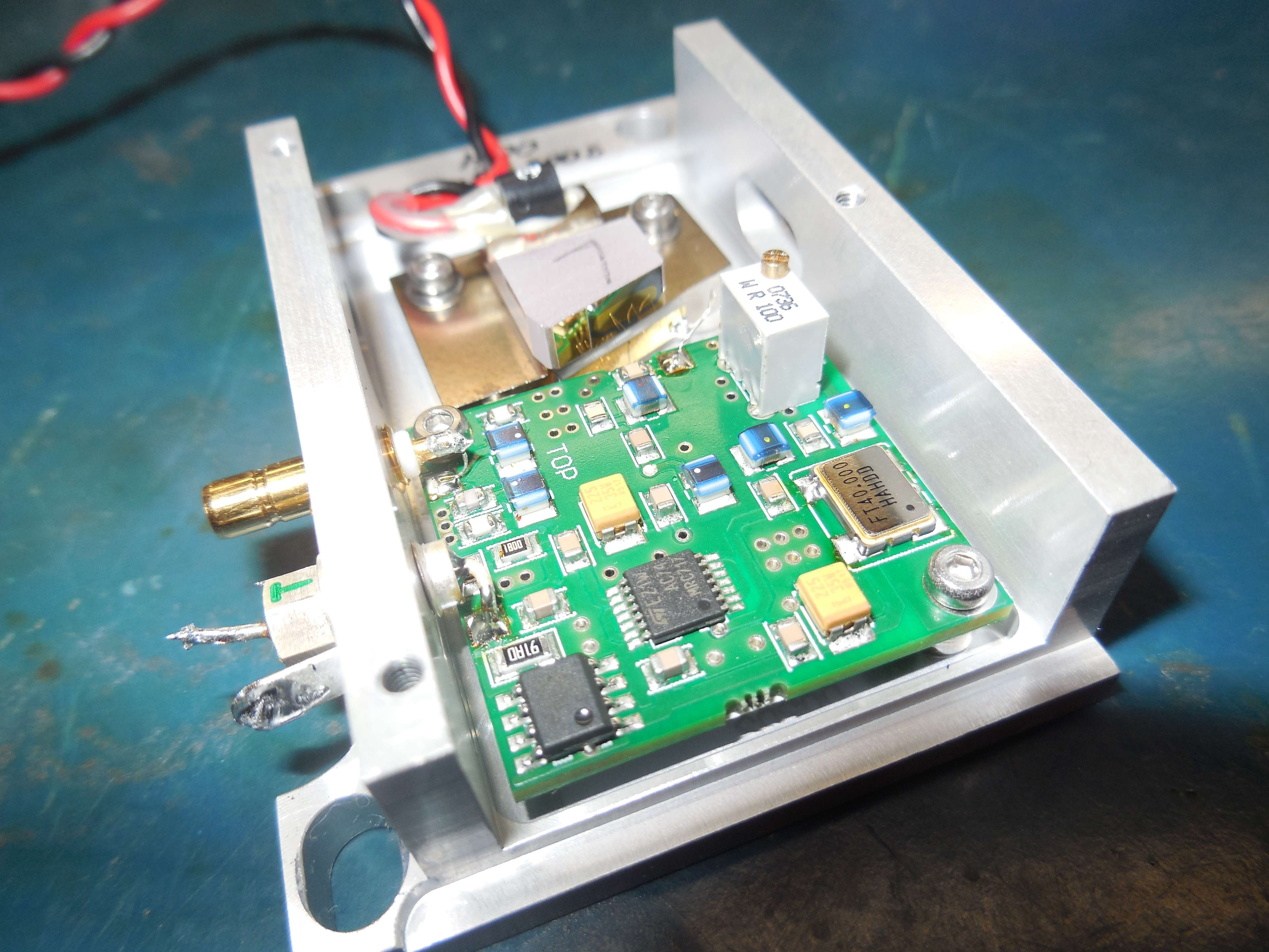
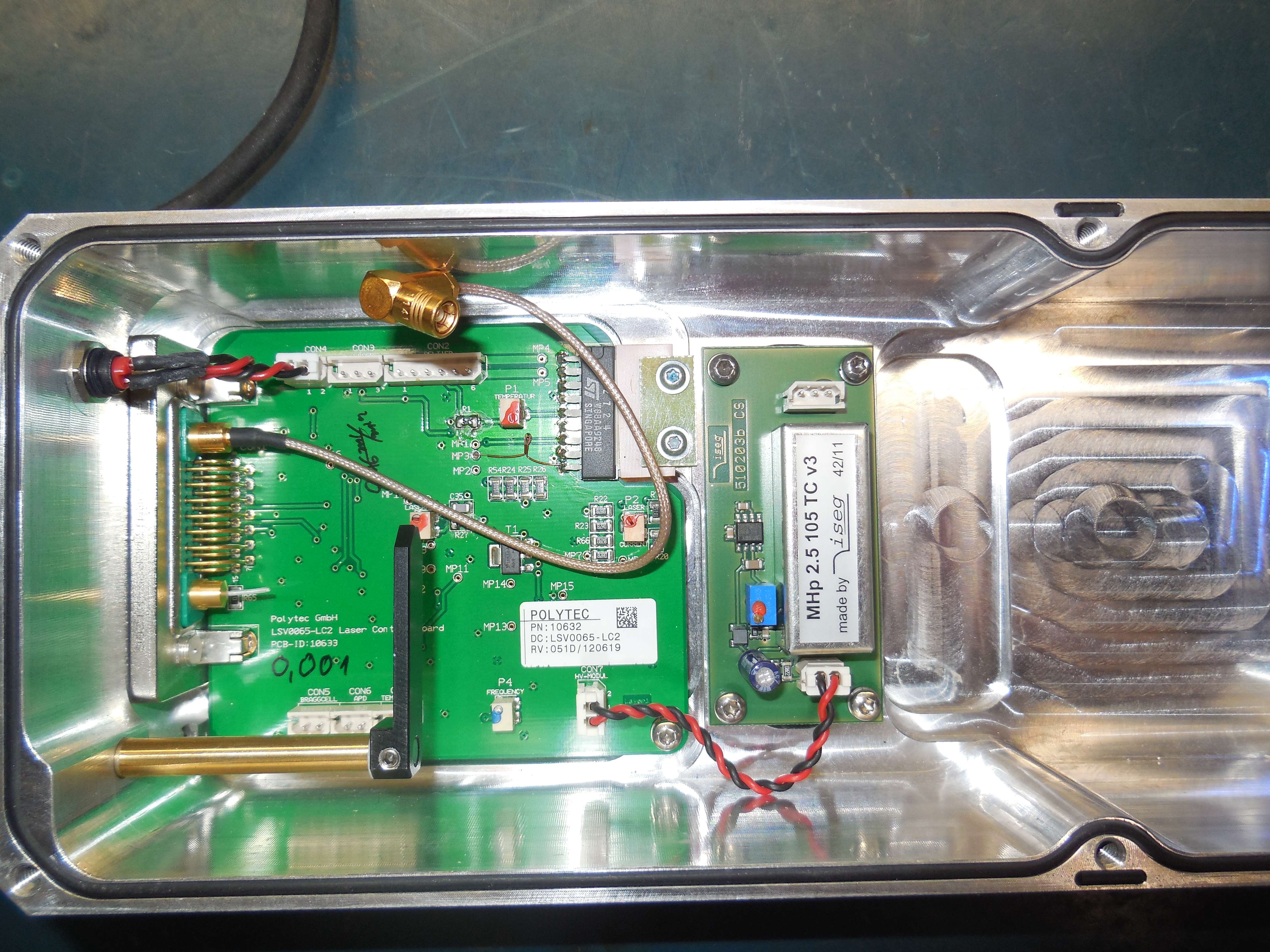
Dual-beam velocimeter, one beam is unmodulated, the other beam is modulated and deflected by the 40 MHz AOM. Receive is via the center-mounted avalanche PIN photodiode.
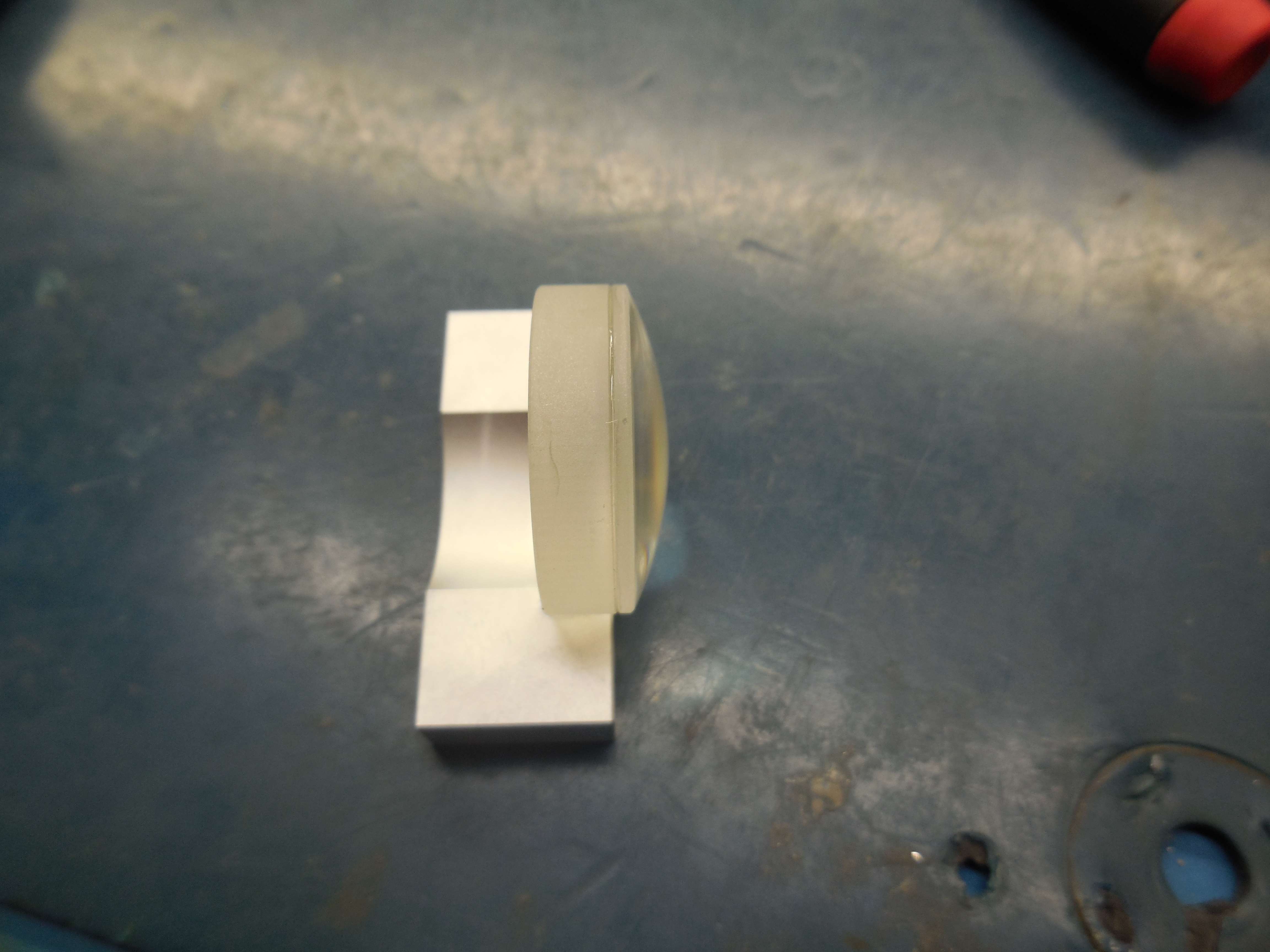
Red laser diode (670 nm) on a Peltier cooler.
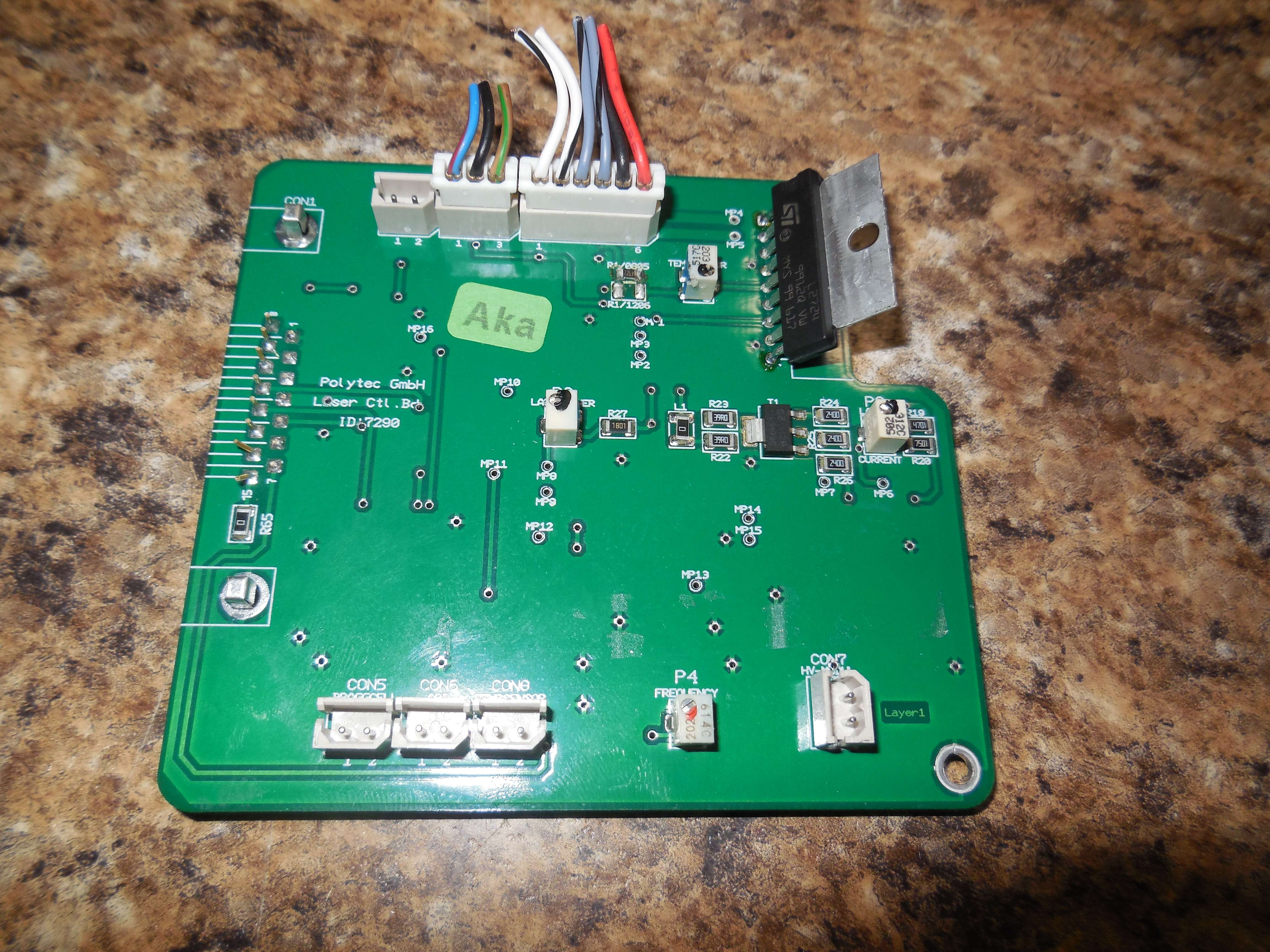
L2724 for Peltier control. Adjust pots for TEMPERATUR (P1), LASERPOWER (P3), LASERCURRENT (P2), and FREQUENCY (P4). The main control board has AD654, AD820A, AD822A, REF02, C393C, ICM555, ILD206 optocoupler.
Main board: BRAGGCELL (CON5, +15V Out), APD (CON6, +15V Out), TEMPSENSOR (CON8, In from Bragg AOM temp sensor), HV-MODUL (CON7, +15V Out), LED (CON4), LASER (CON3, 3 wires), PELTIER (CON2, 6 wires, red & black go to Peltier, the others are thermistors)
The 8-pin IC on the HV board is a AD780 used for the 2.5V voltage set.
40 MHz Bragg AOM has an internal clock source and a 10 MHz reference output which is divided down from the 40 MHz crystal.
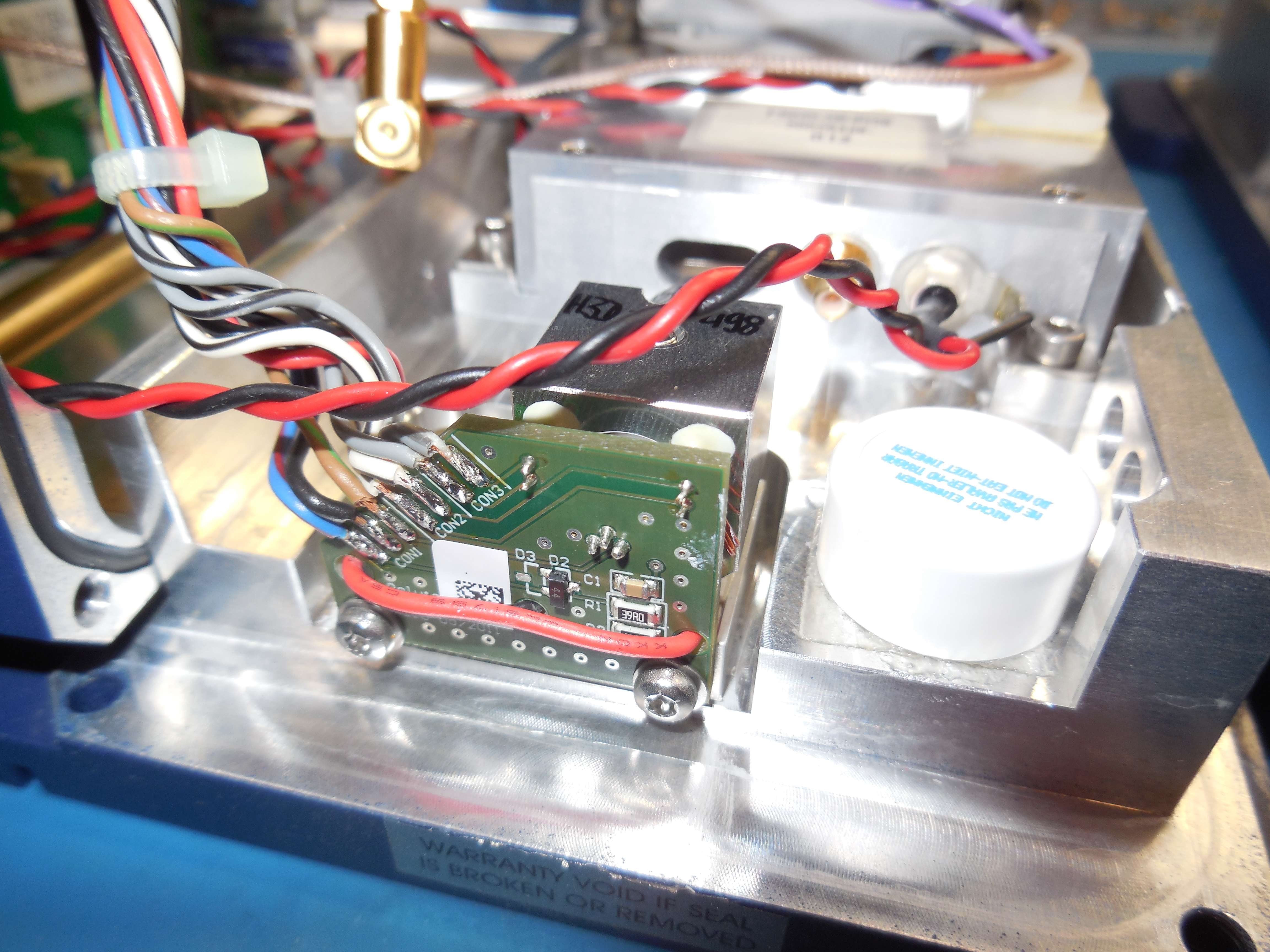
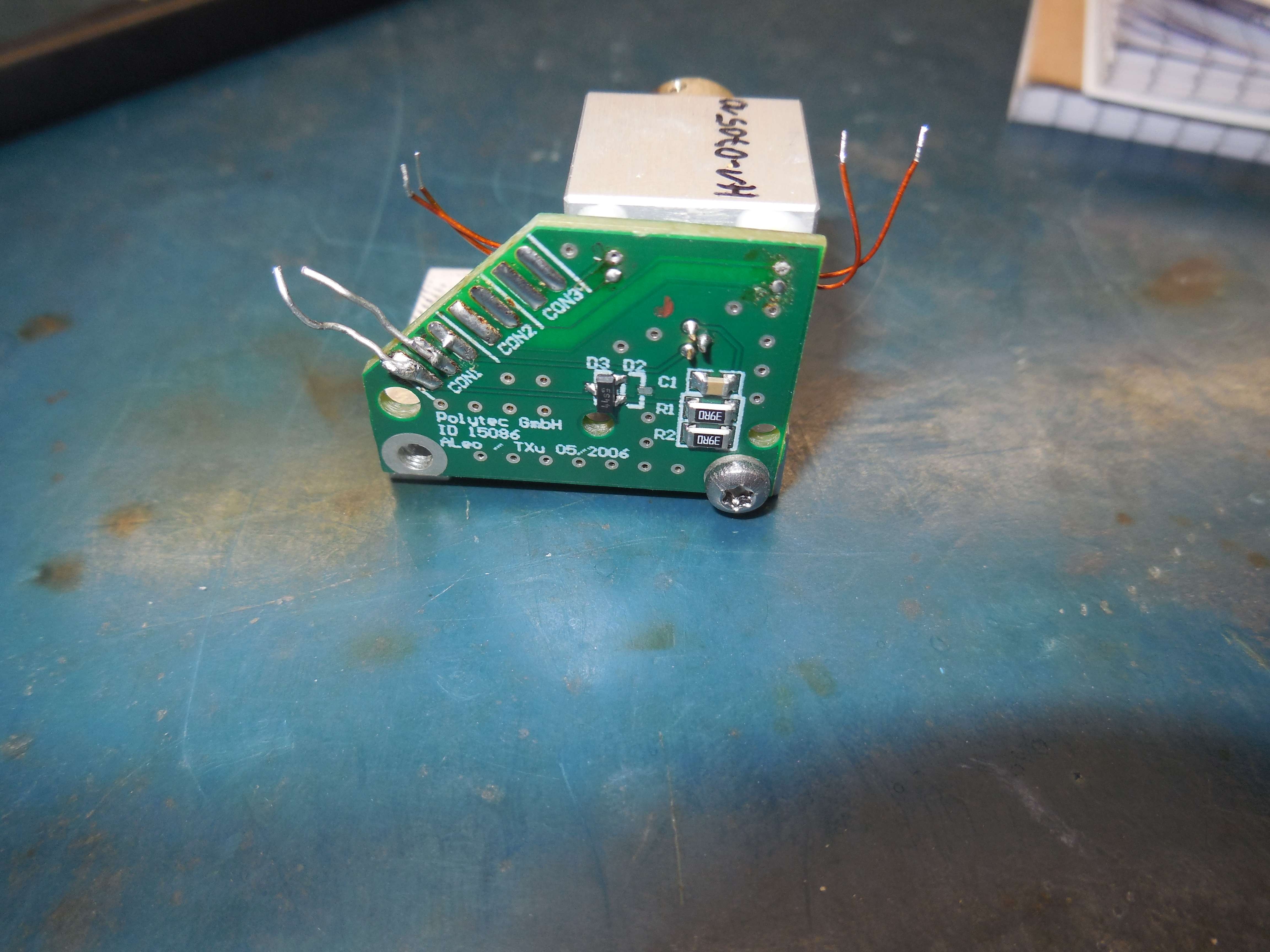
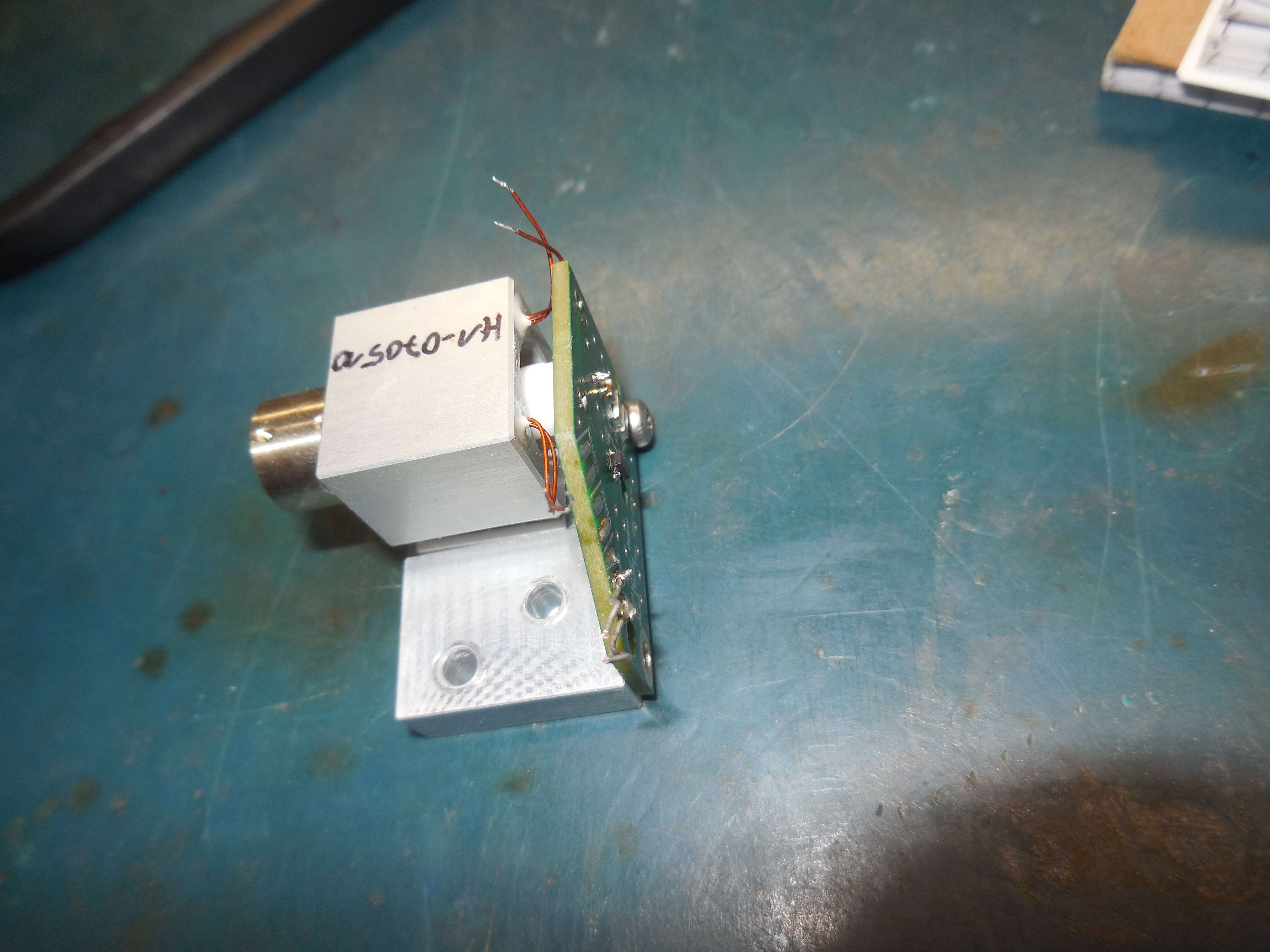
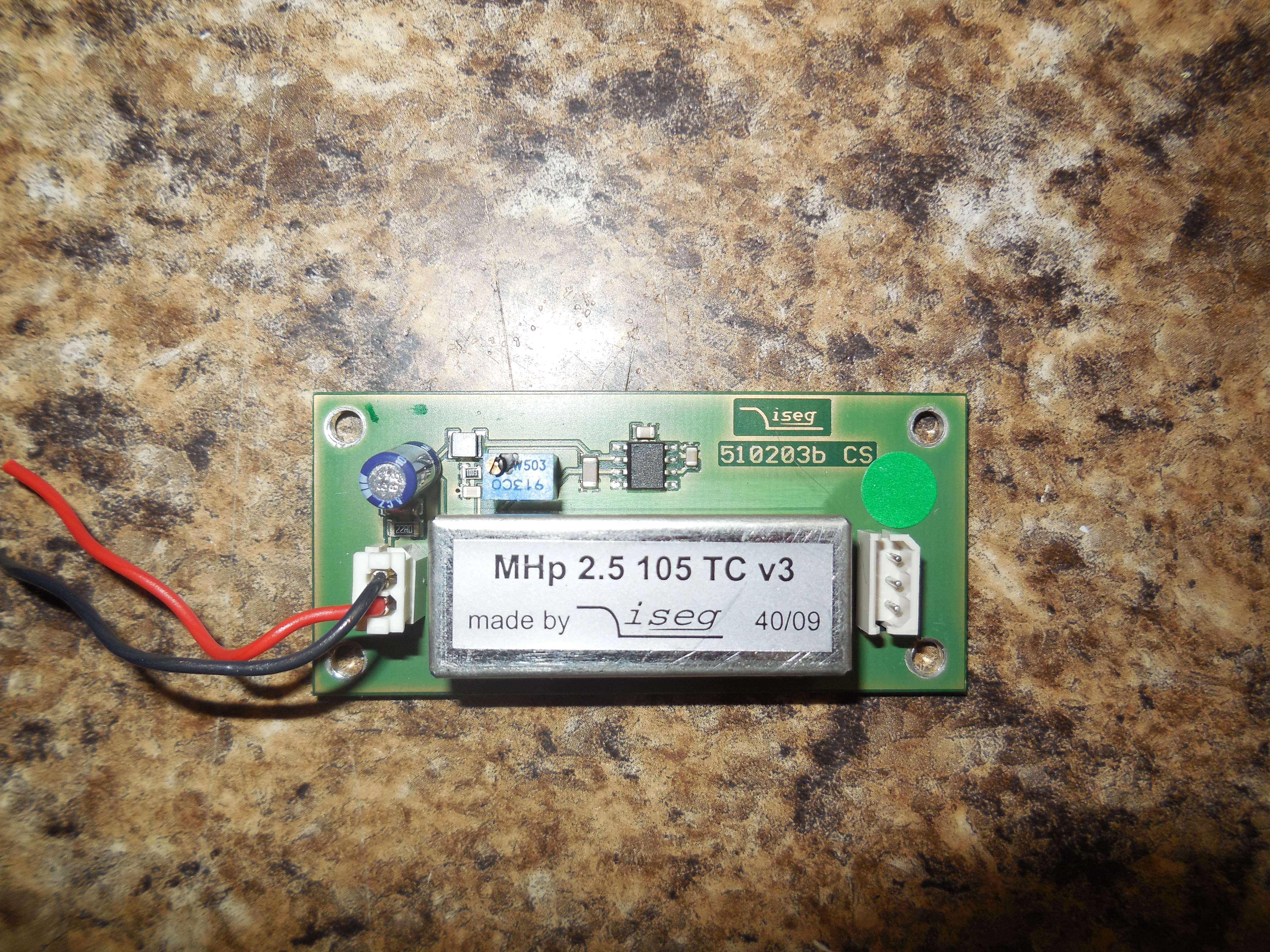
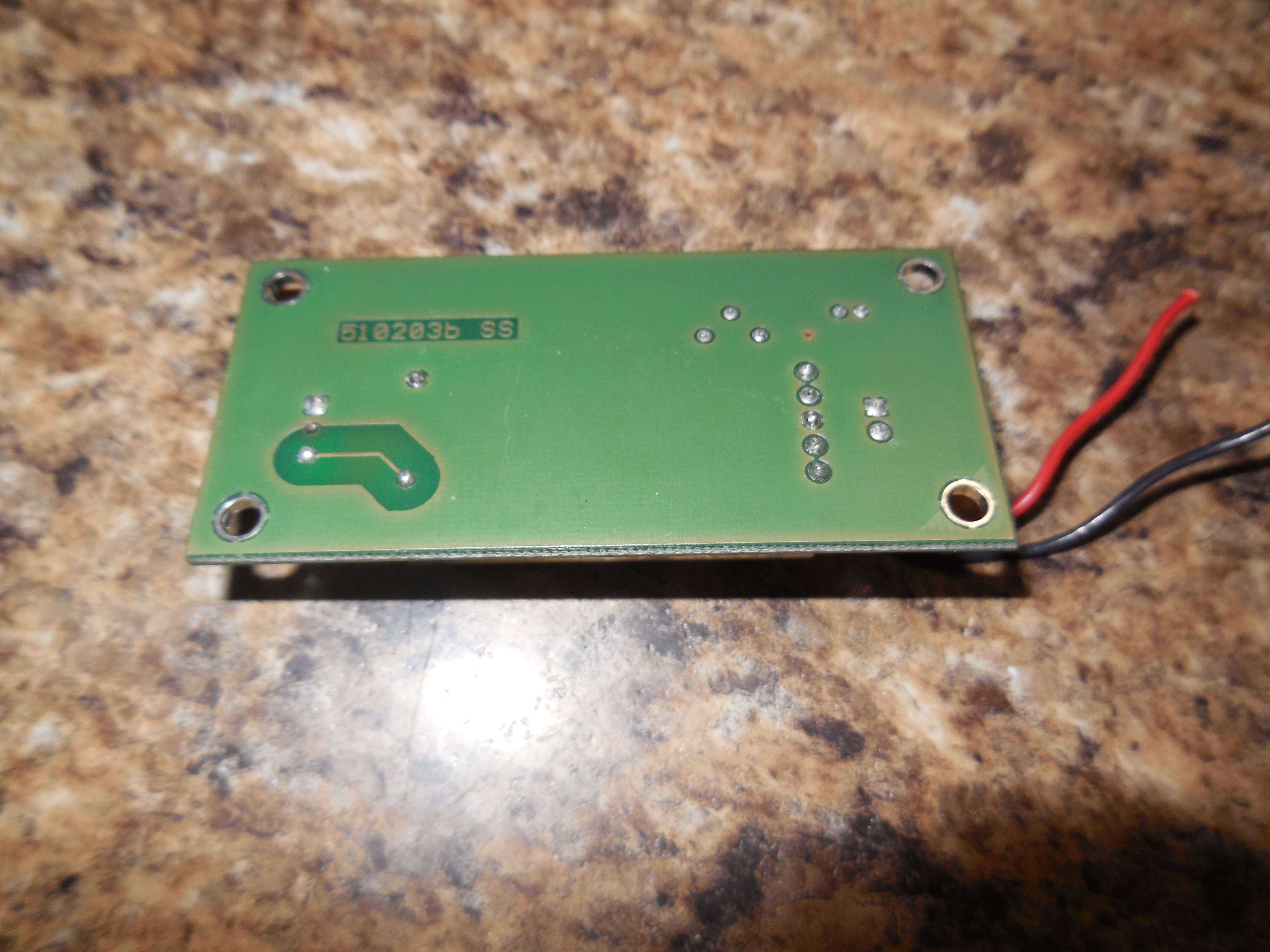
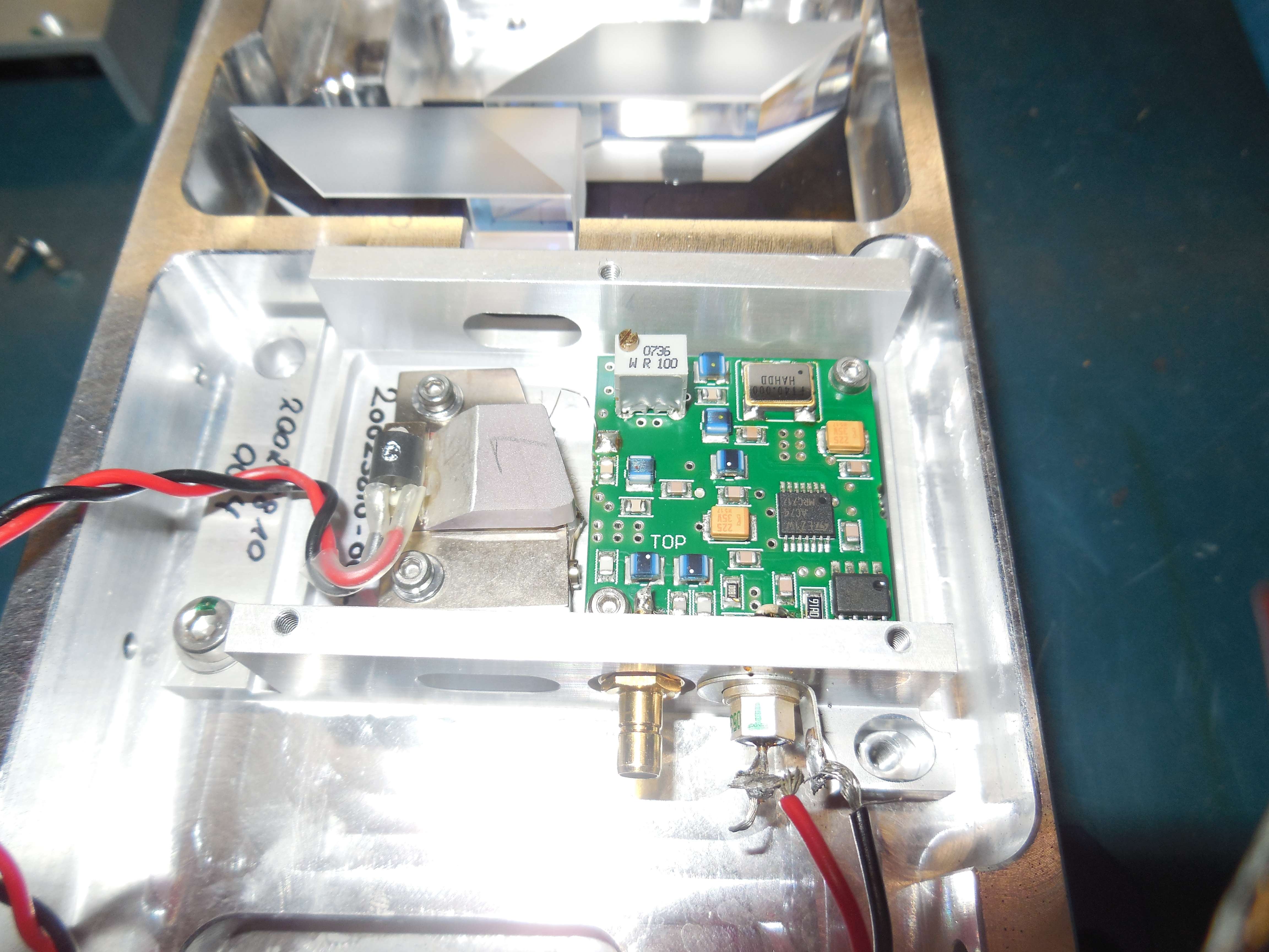
Avalanche PIN photodiode (A1631 or A5163, unknown manufacture) with a +230 VDC (iseg MHp-2.5-105-TC-v3) reverse bias, CXA1685 (or AD8015), 78L05, MCL MAR-8 MMIC. The photodiode module provides a 50 ohm output.
Coax outputs for 10 MHz Reference and Signal.
DBM-17W2S Pin-Out Guesses: 1: Ground 2: No Connection 3: +15 VDC 4: Ground 5: Ground 6: +15 VDC 7: Goes to ILD206 pin 8 (collector output, which is an isocoupled output from the AD654, which has it Vctrl input from the Bragg AOM temp sensor) 8: To CON2 on Laser Diode Block (Thermistor?) 9: To CON2 on Laser Diode Block (Thermistor?) 10: -15 VDC 11: Goes to ILD206 pin 8 (collector output) 12: +5 VDC Laser On (There is a delay for the Peltier to come to temperature.) 13: -5 VDC (There is a high peak current for Peltier, then settles down to 200 mA or so.) 14: No Connection 15: Ground |
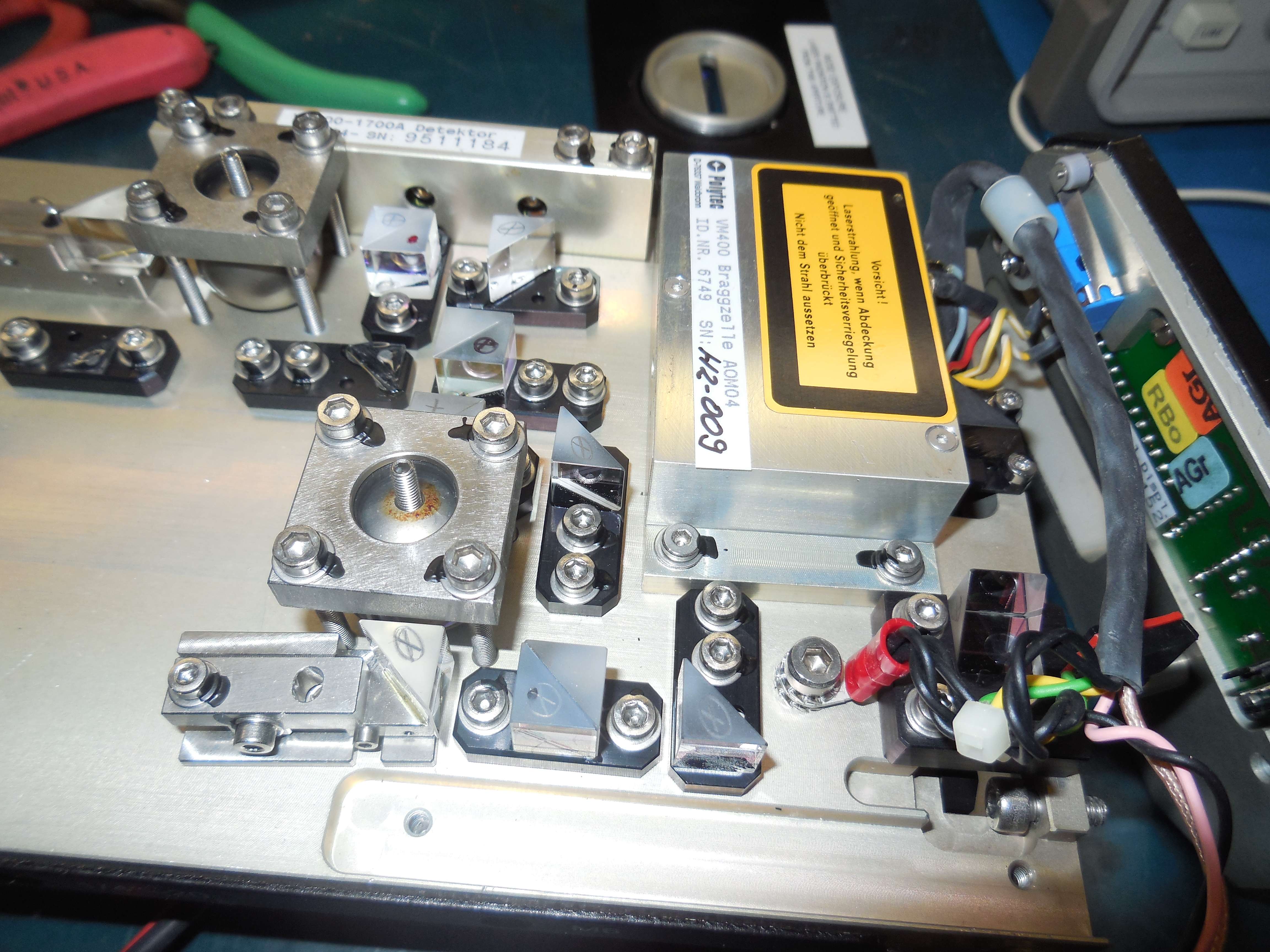
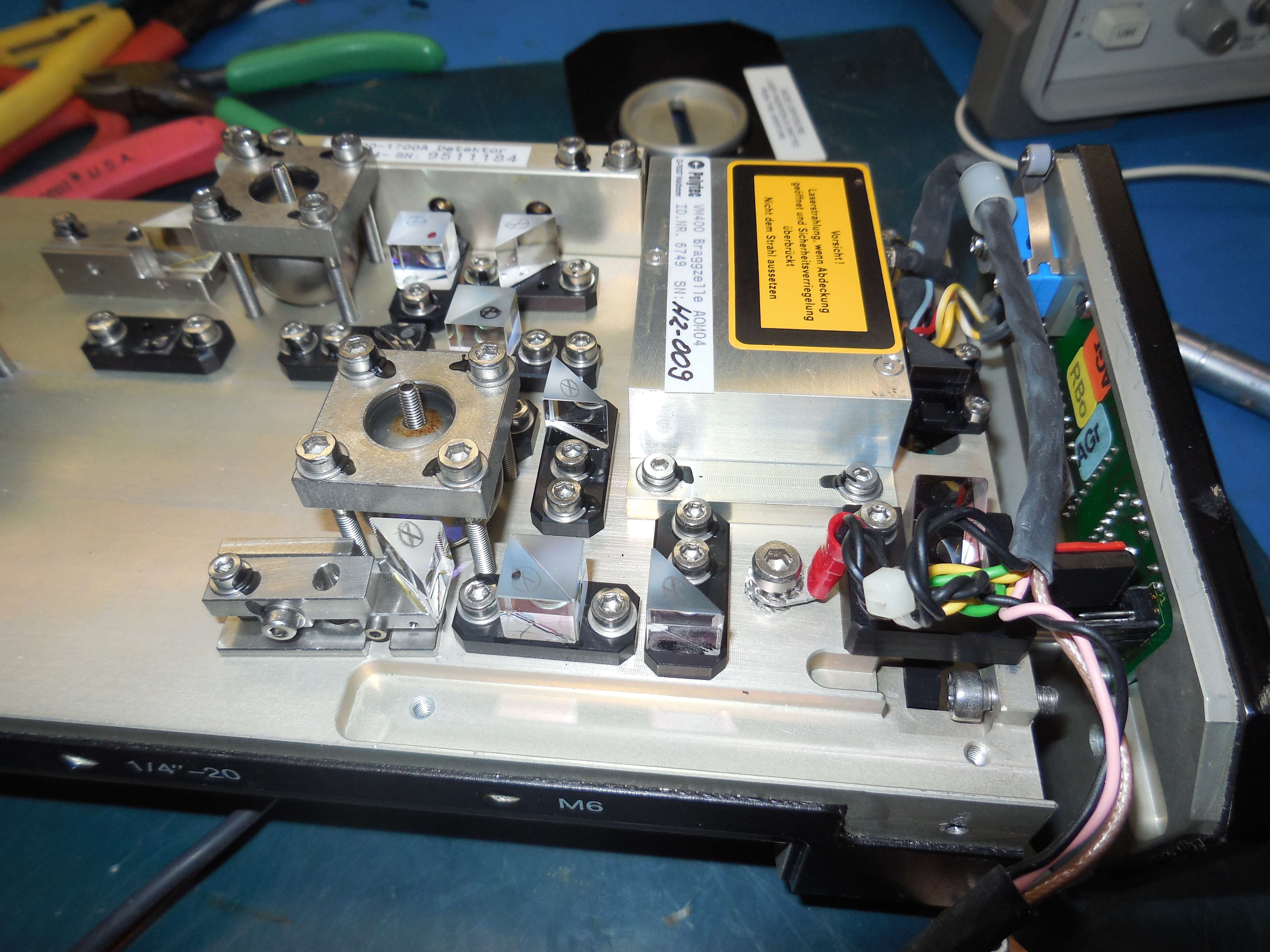
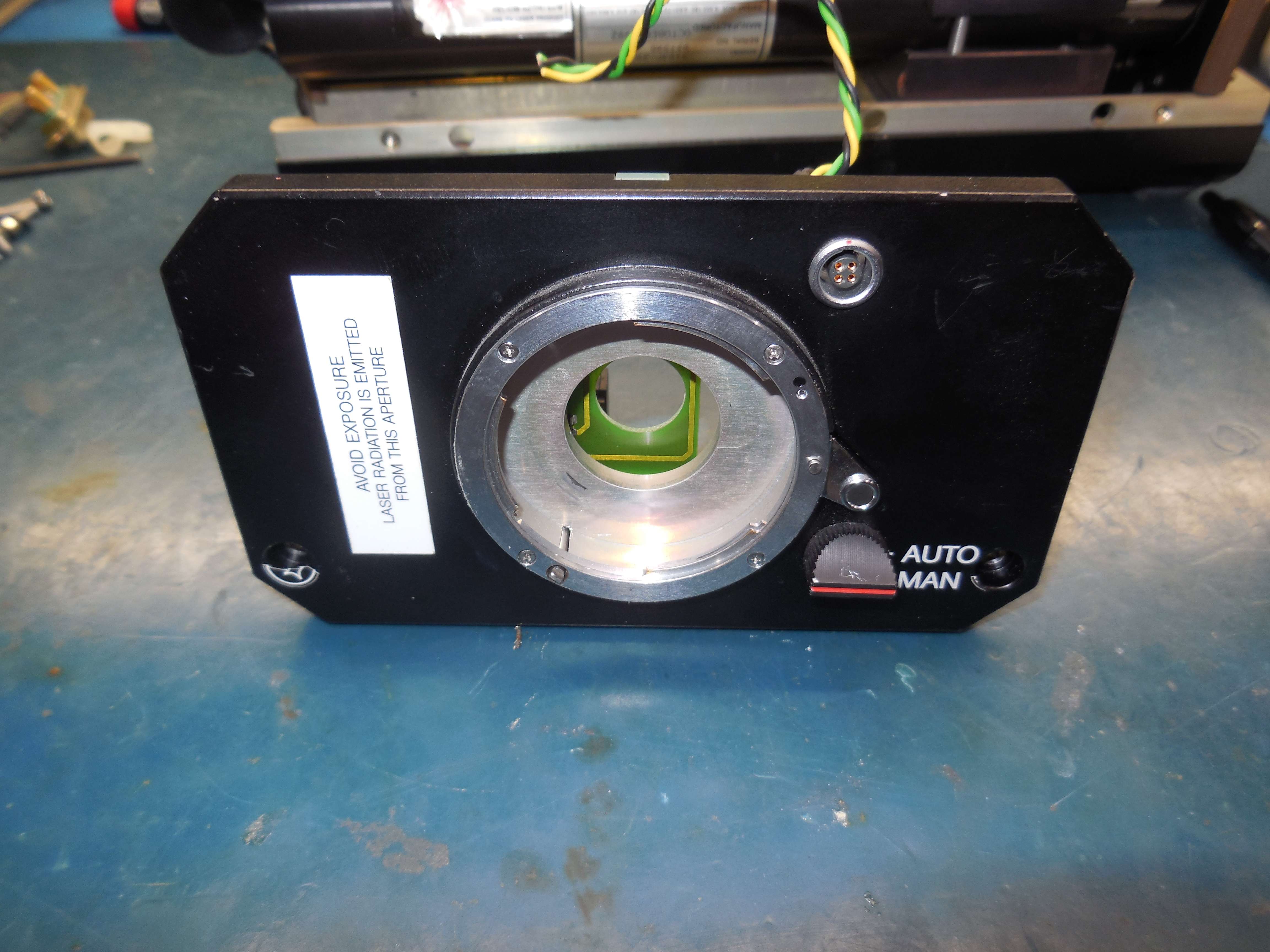
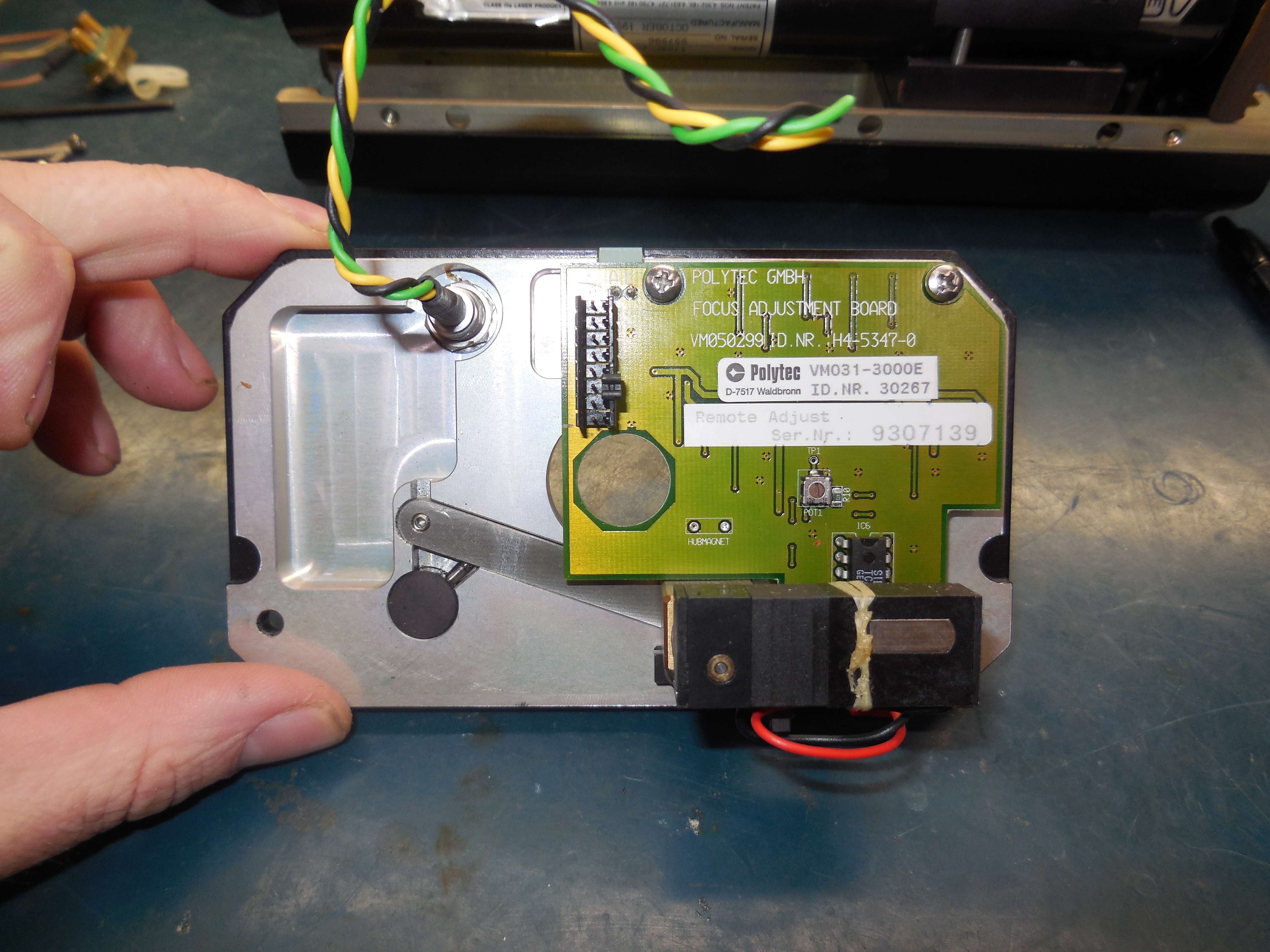
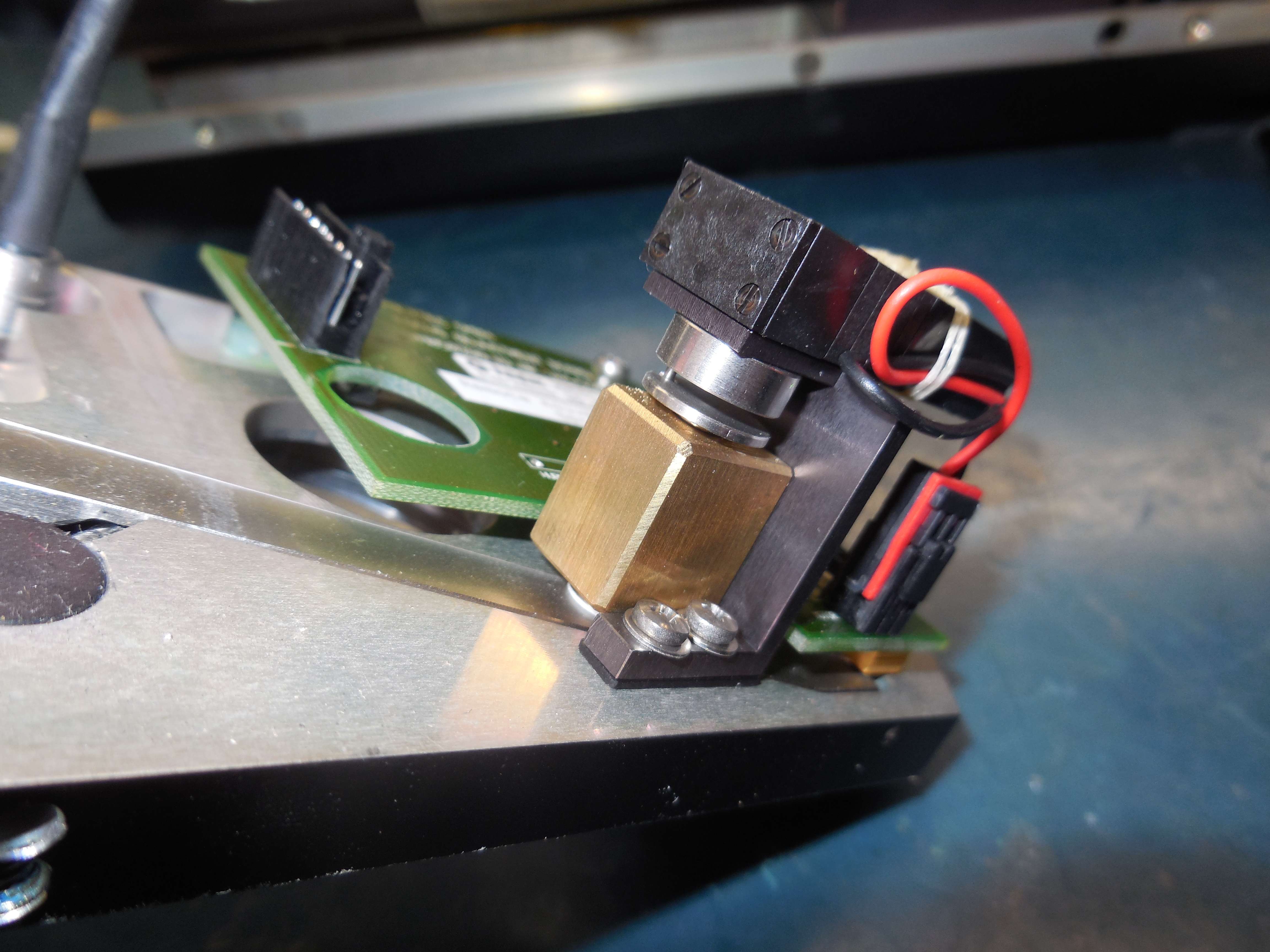
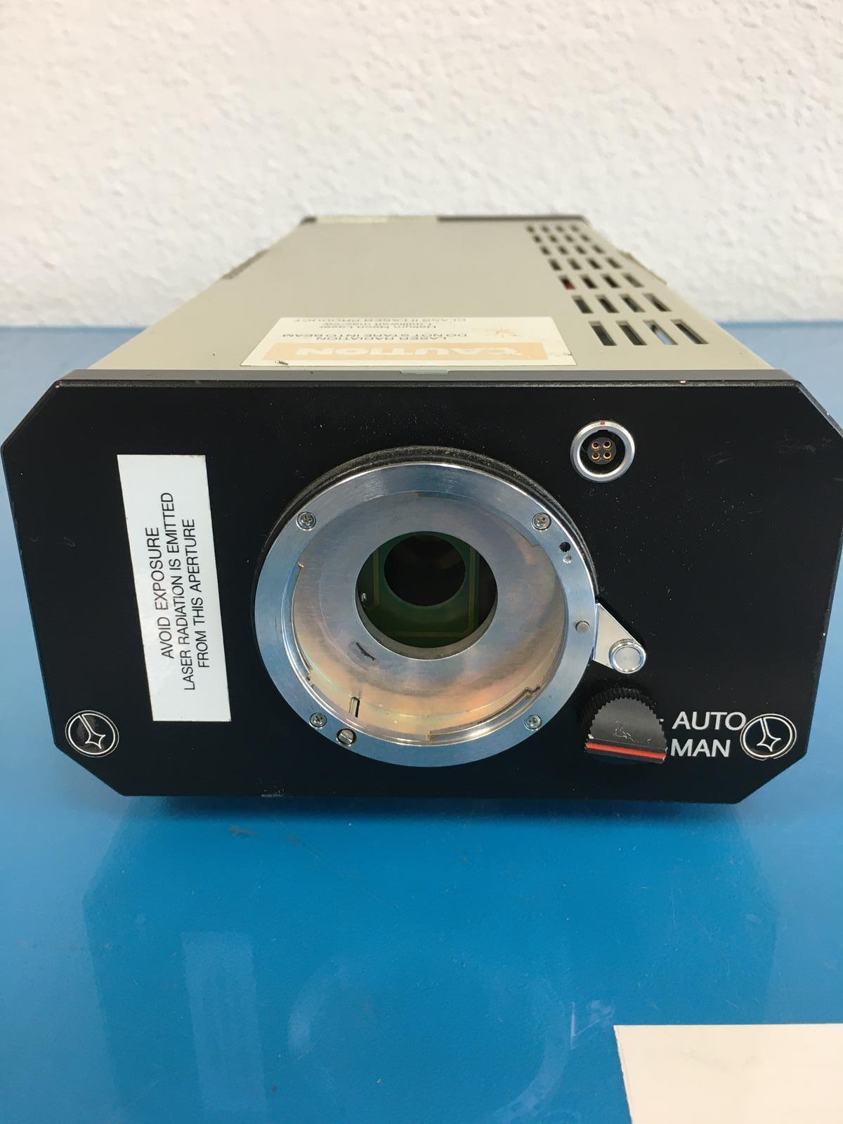
OFV-400 Sensor Head
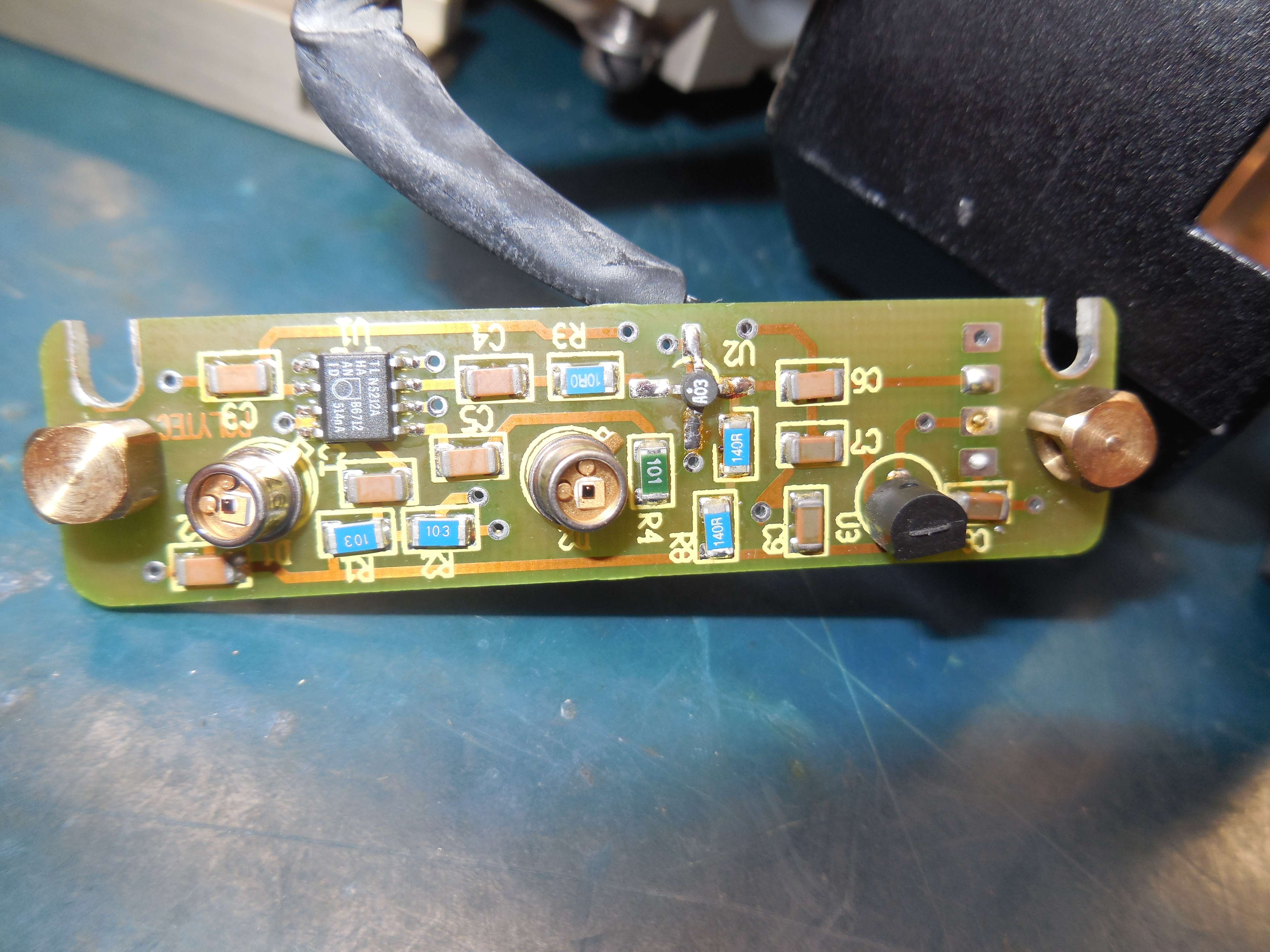
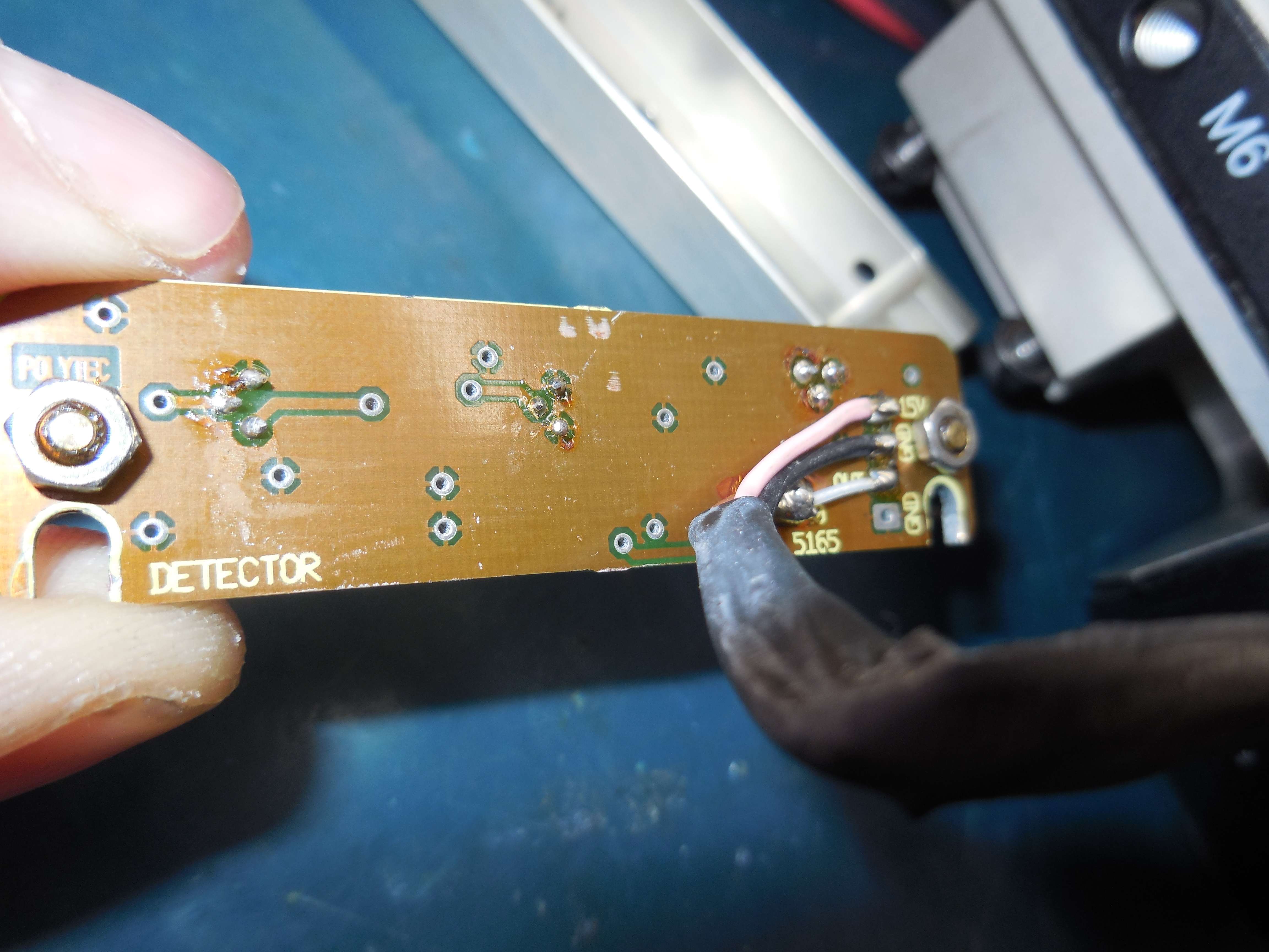


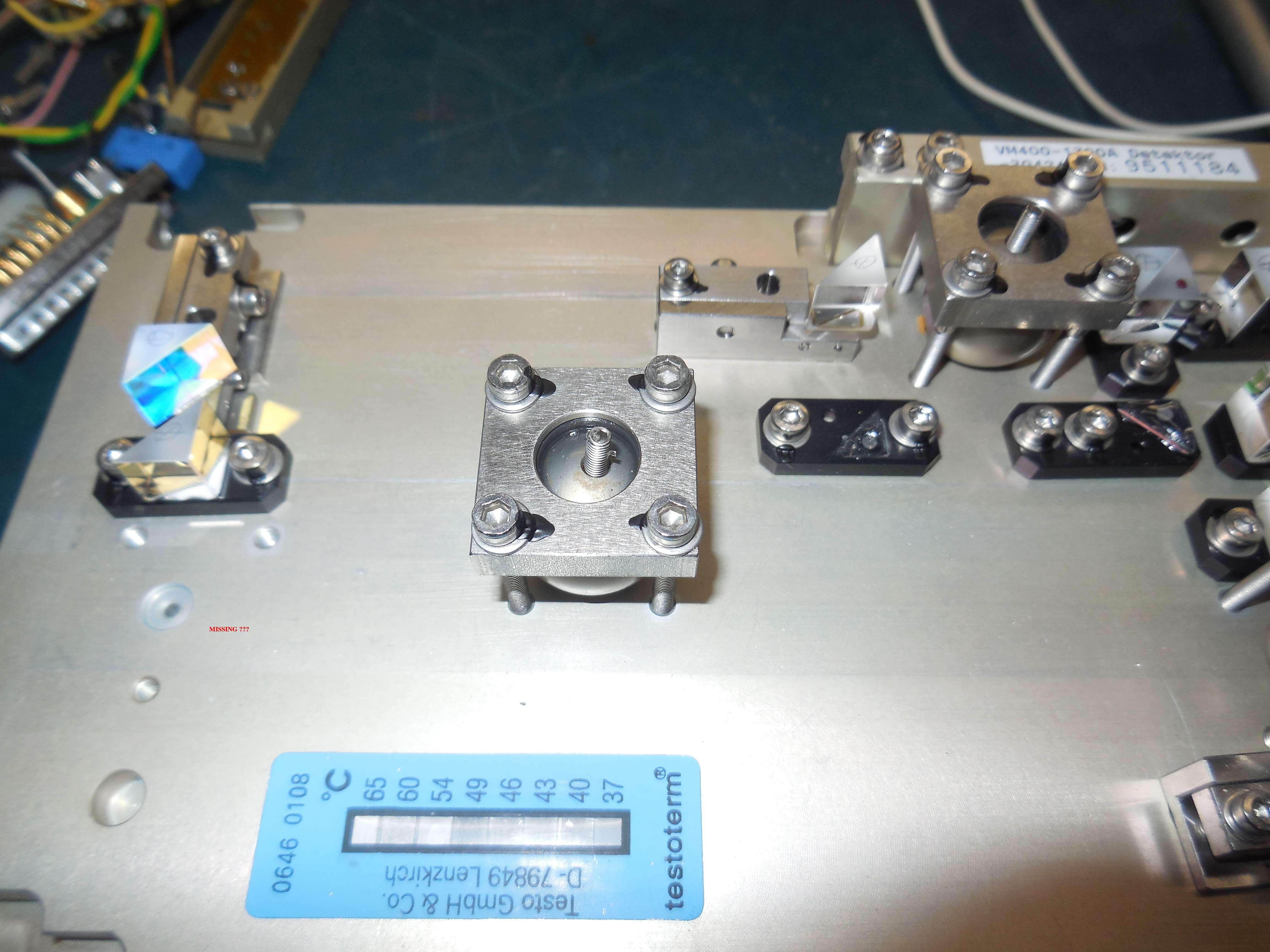
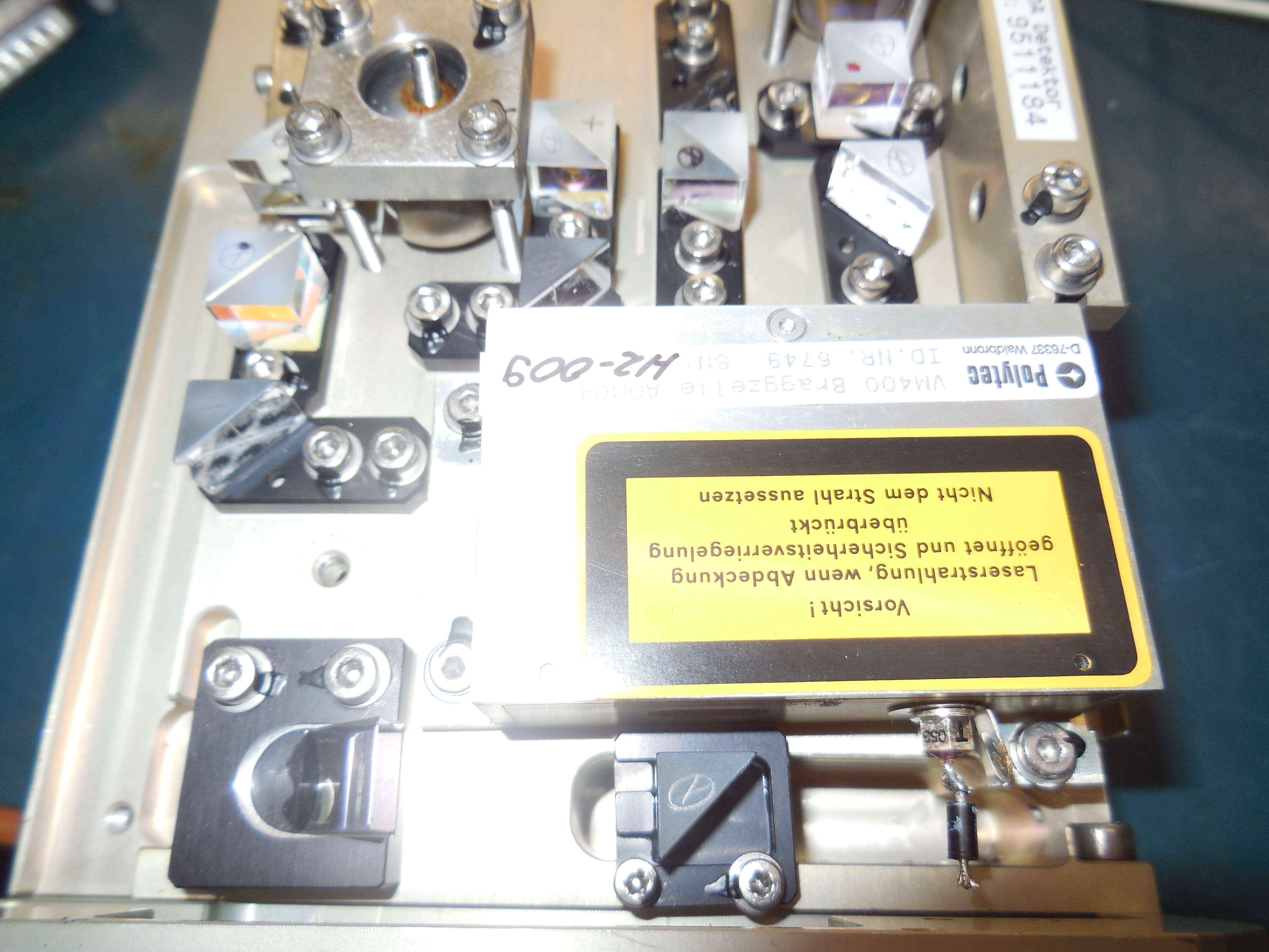
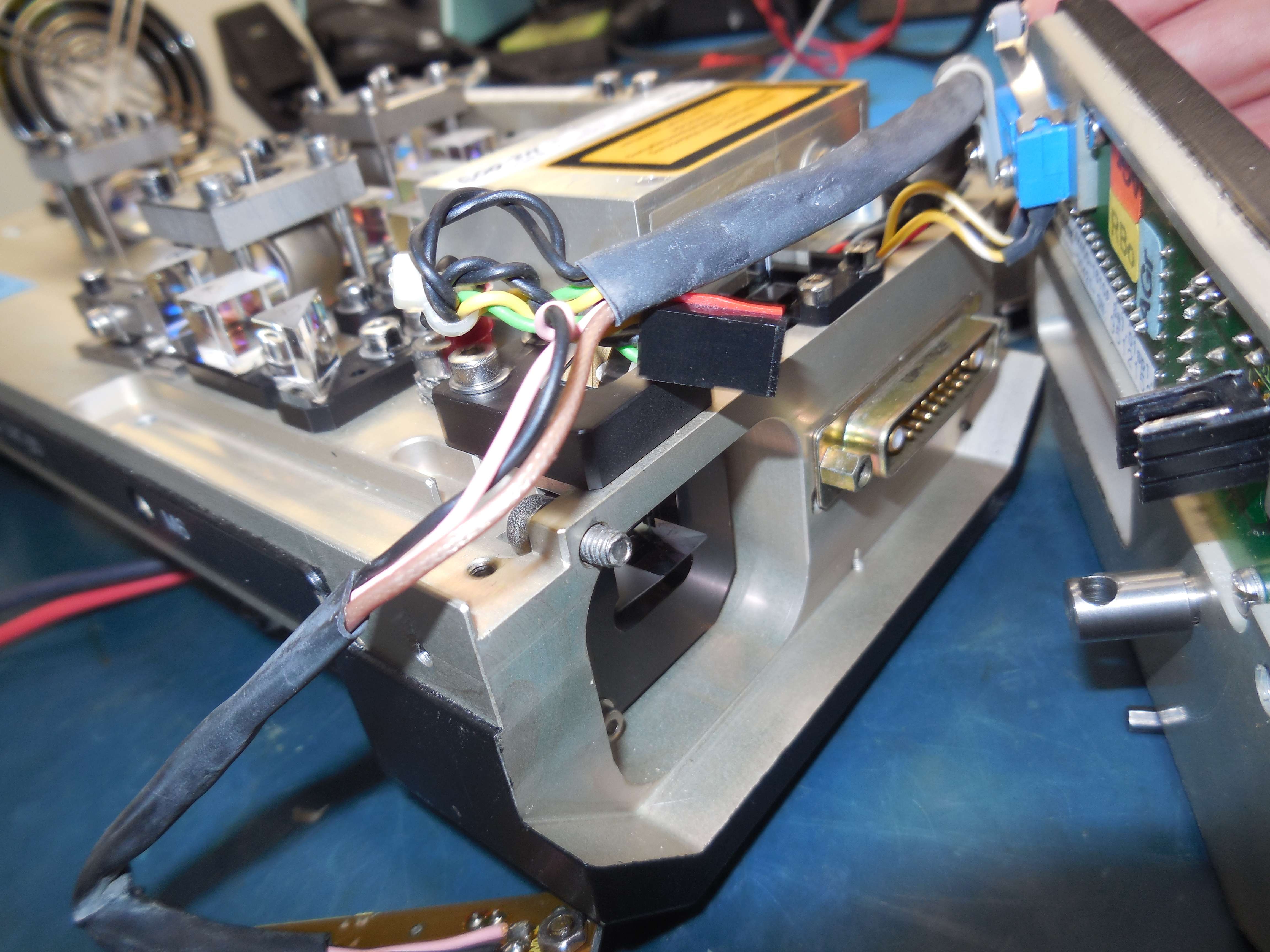
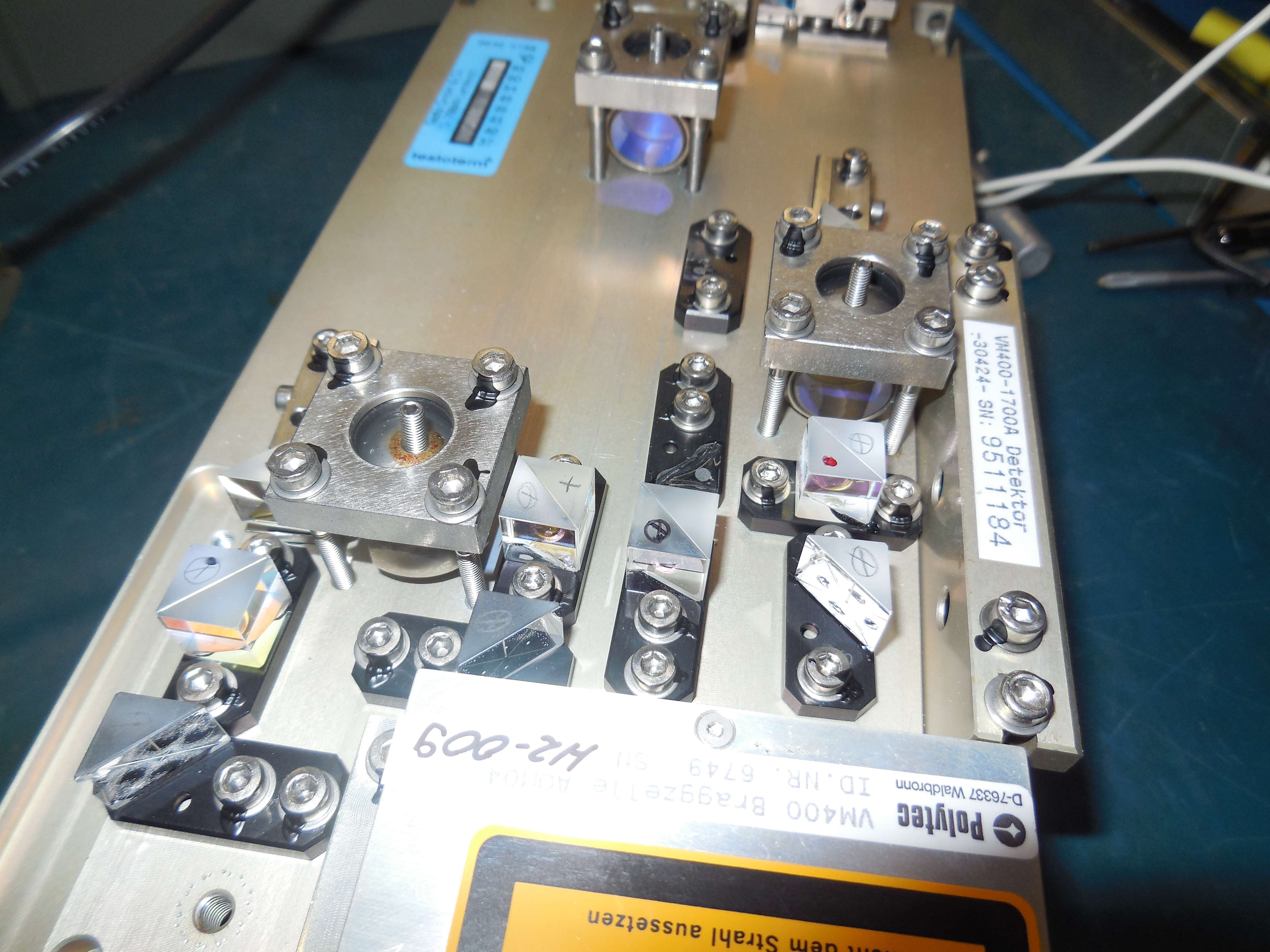
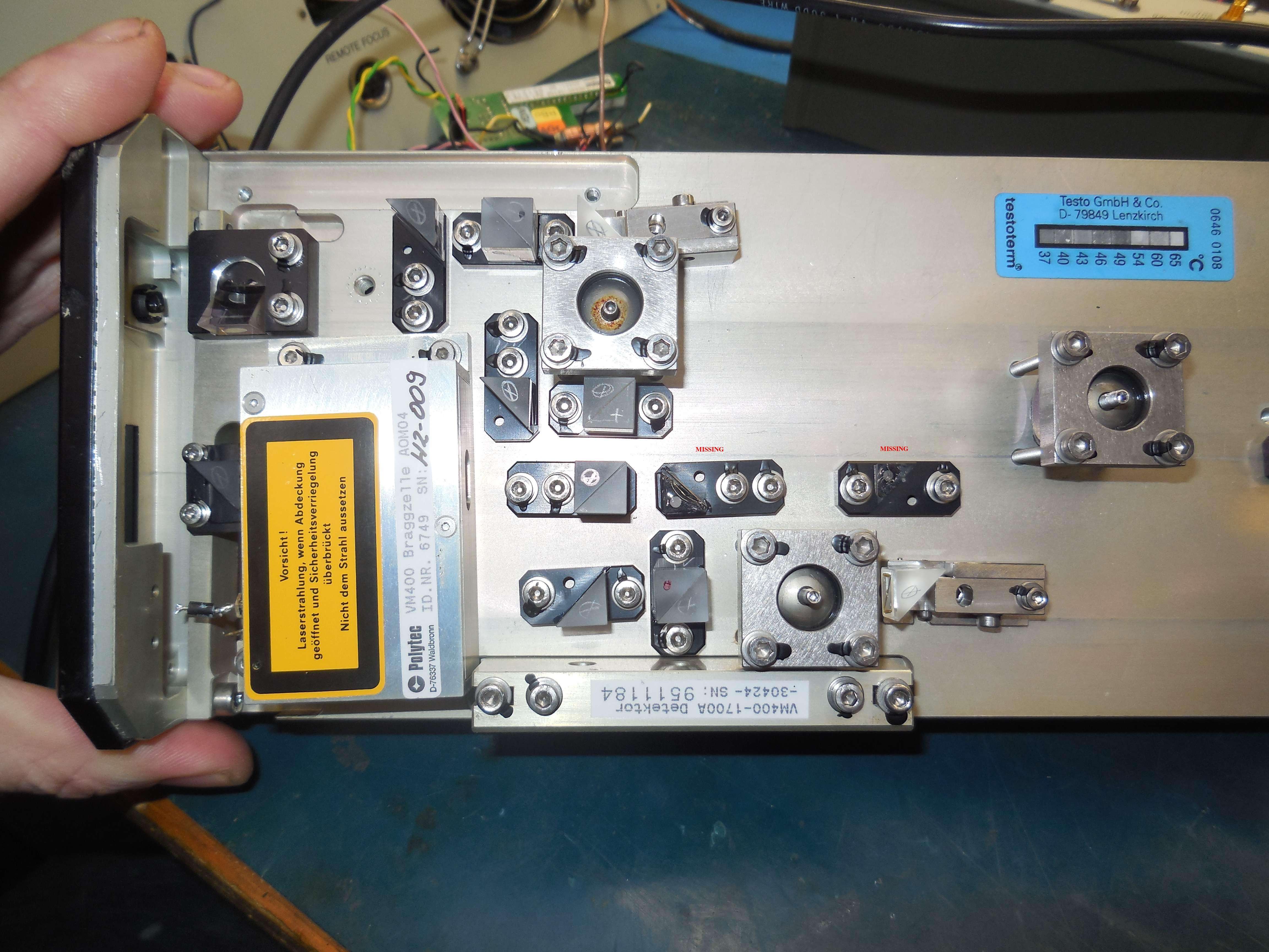
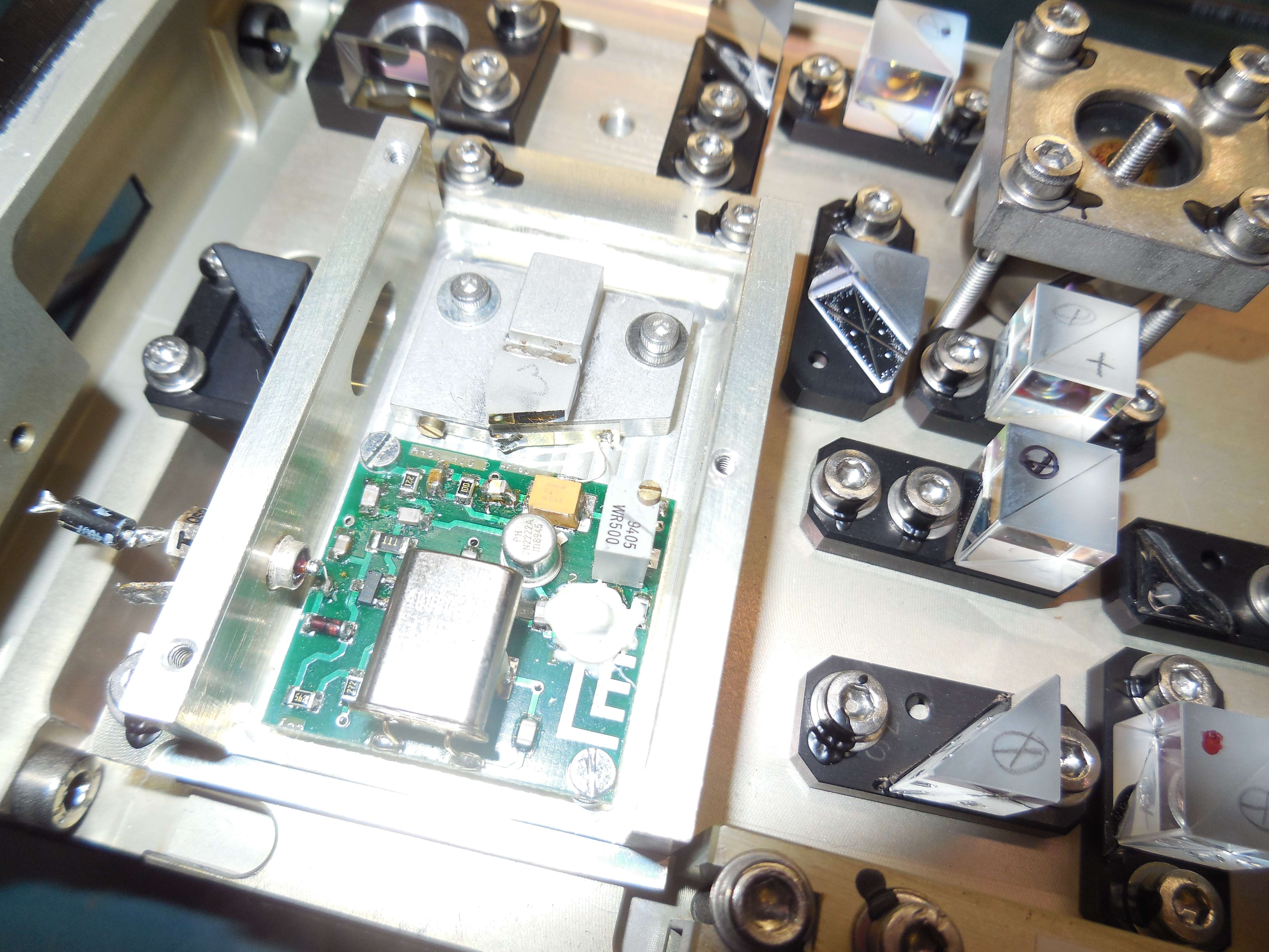
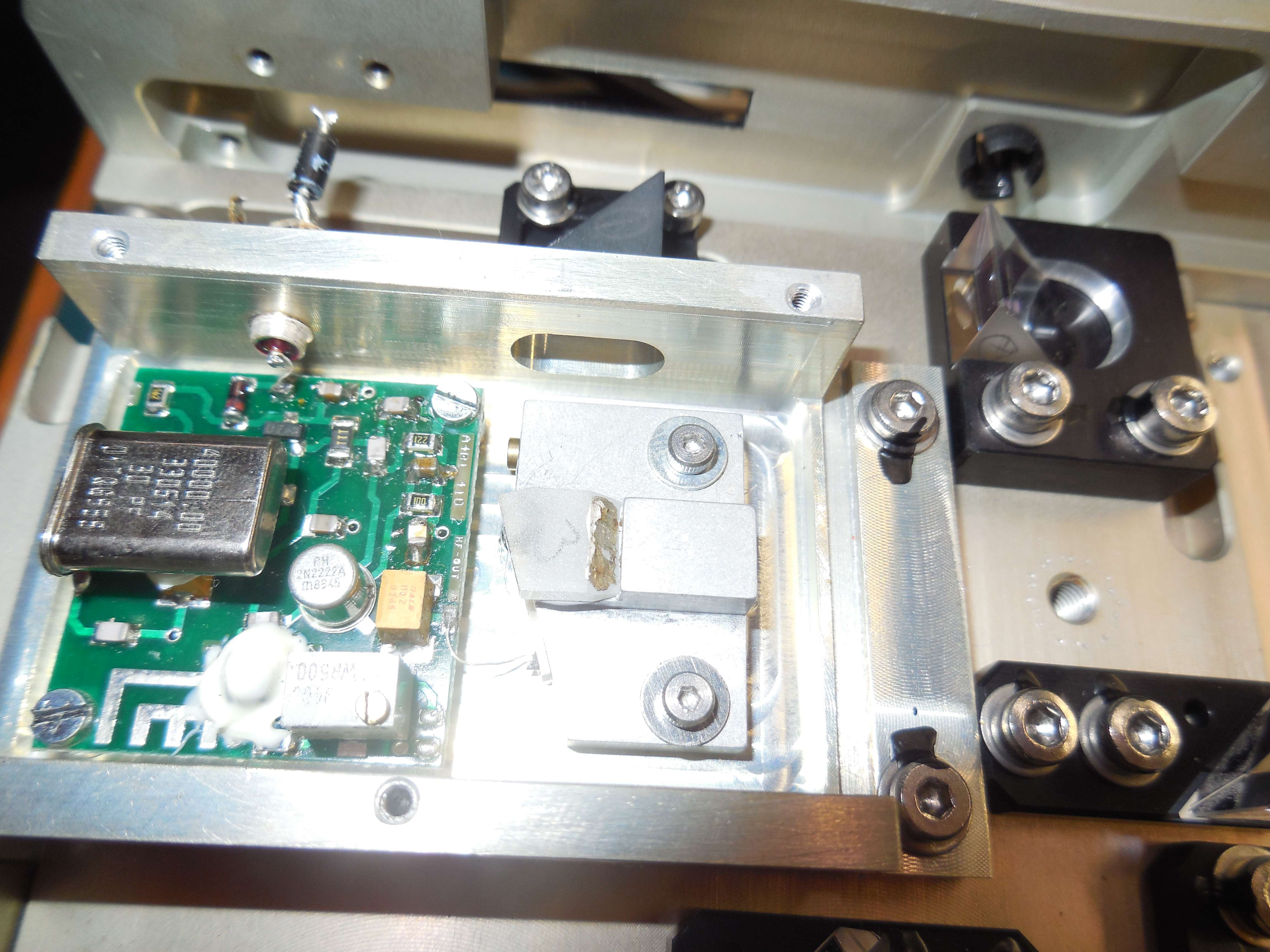
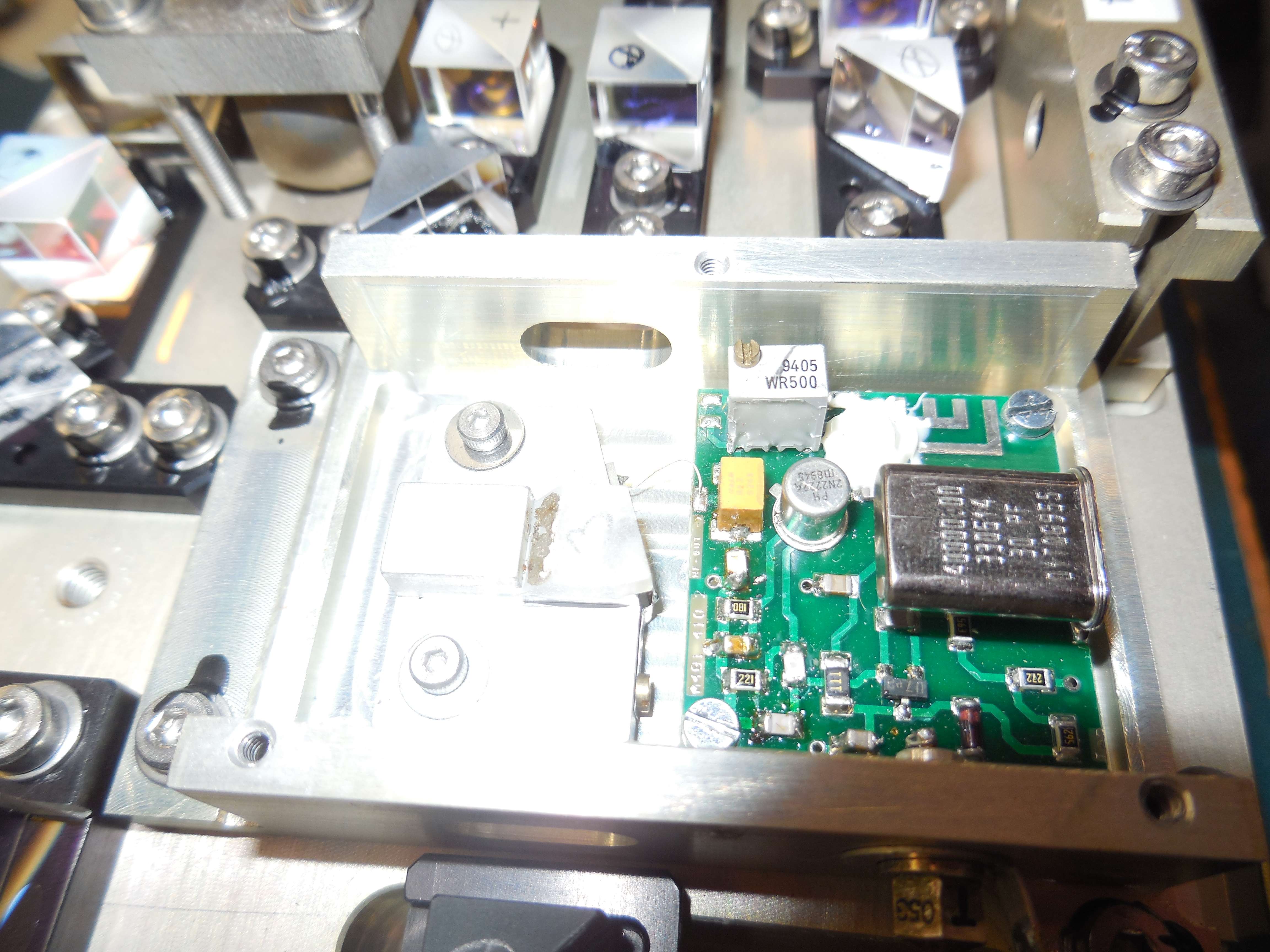
Dual BPW97 PIN photodiodes (VM400-1700A) in a differential config and slightly tilted (?), NE5212A, MCL MAR-3 MMIC?
This was a "parts" unit and is missing some of the optics (not sure which ones!).
The Bragg AOM (VM400) has an internal 40 MHz source and is powered by +15 VDC.
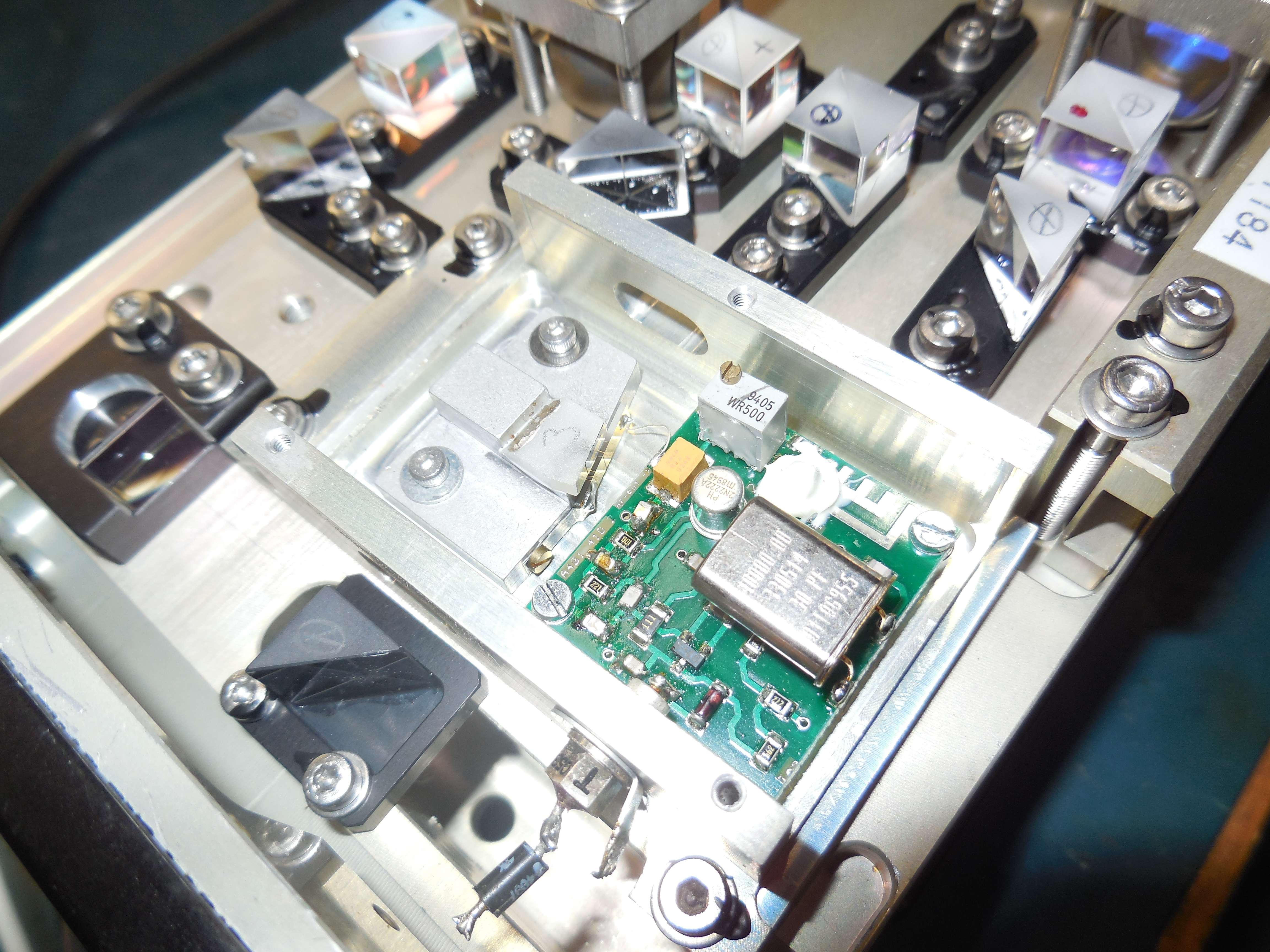
OFV-302 Sensor Head
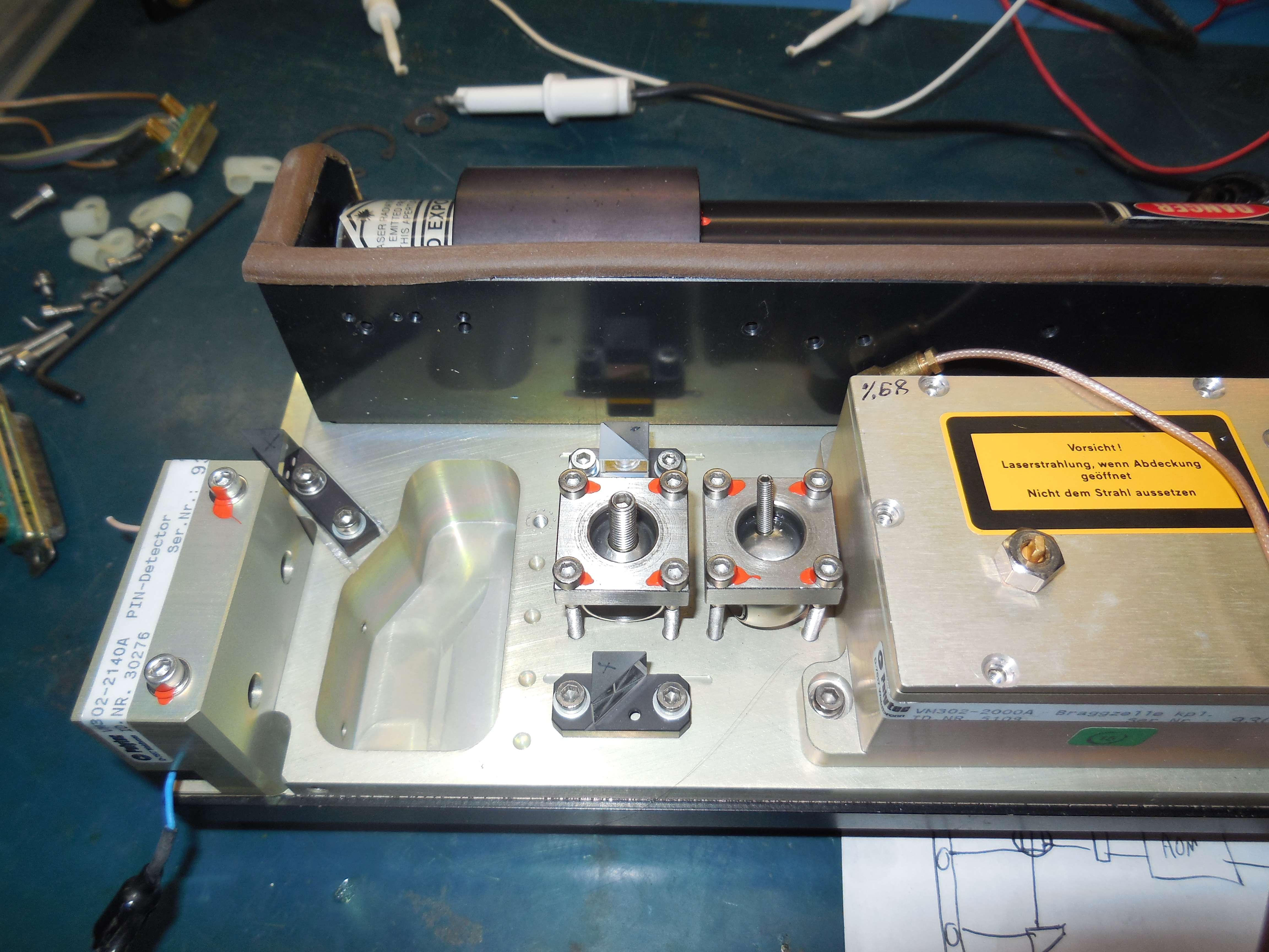
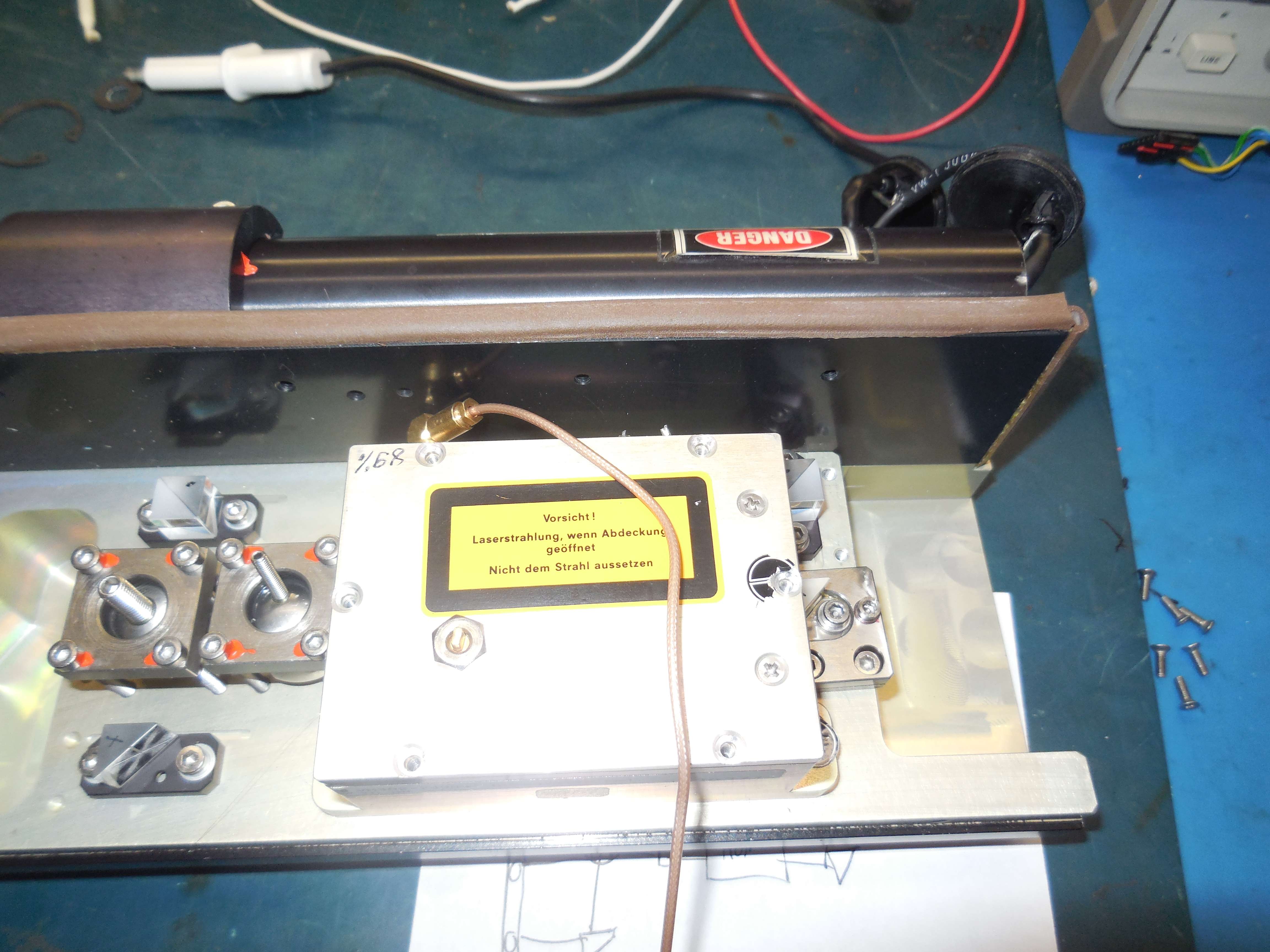
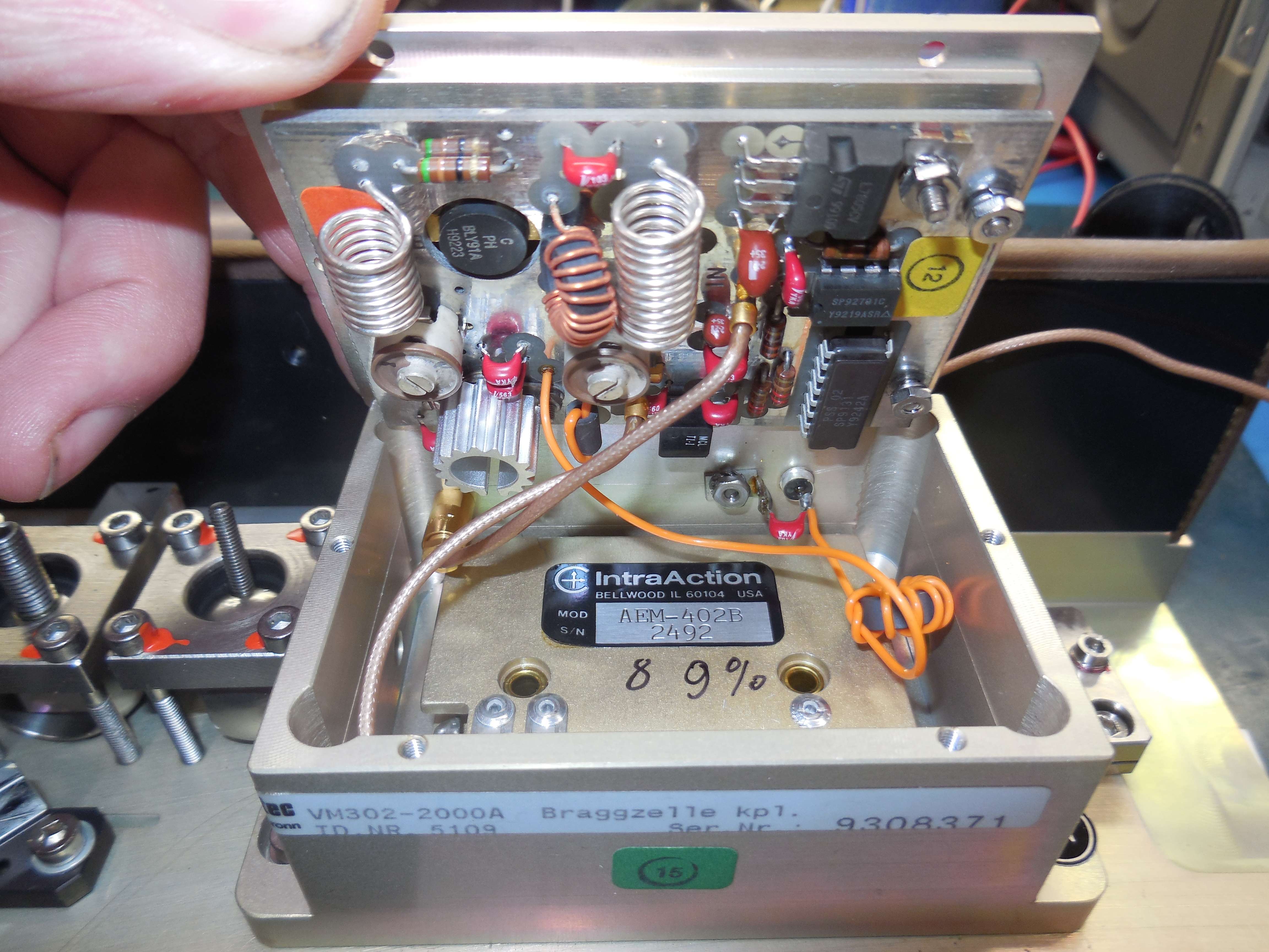
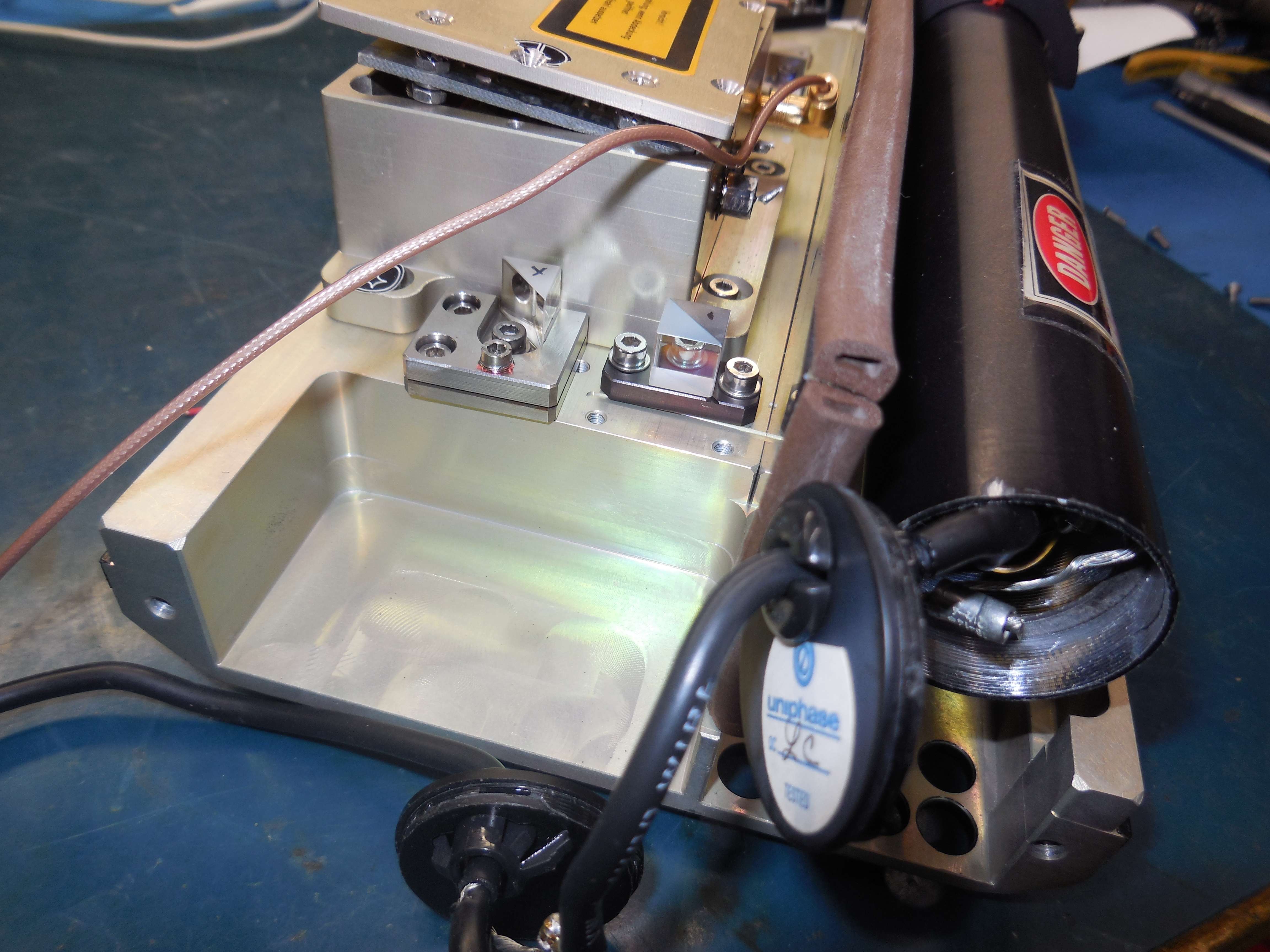
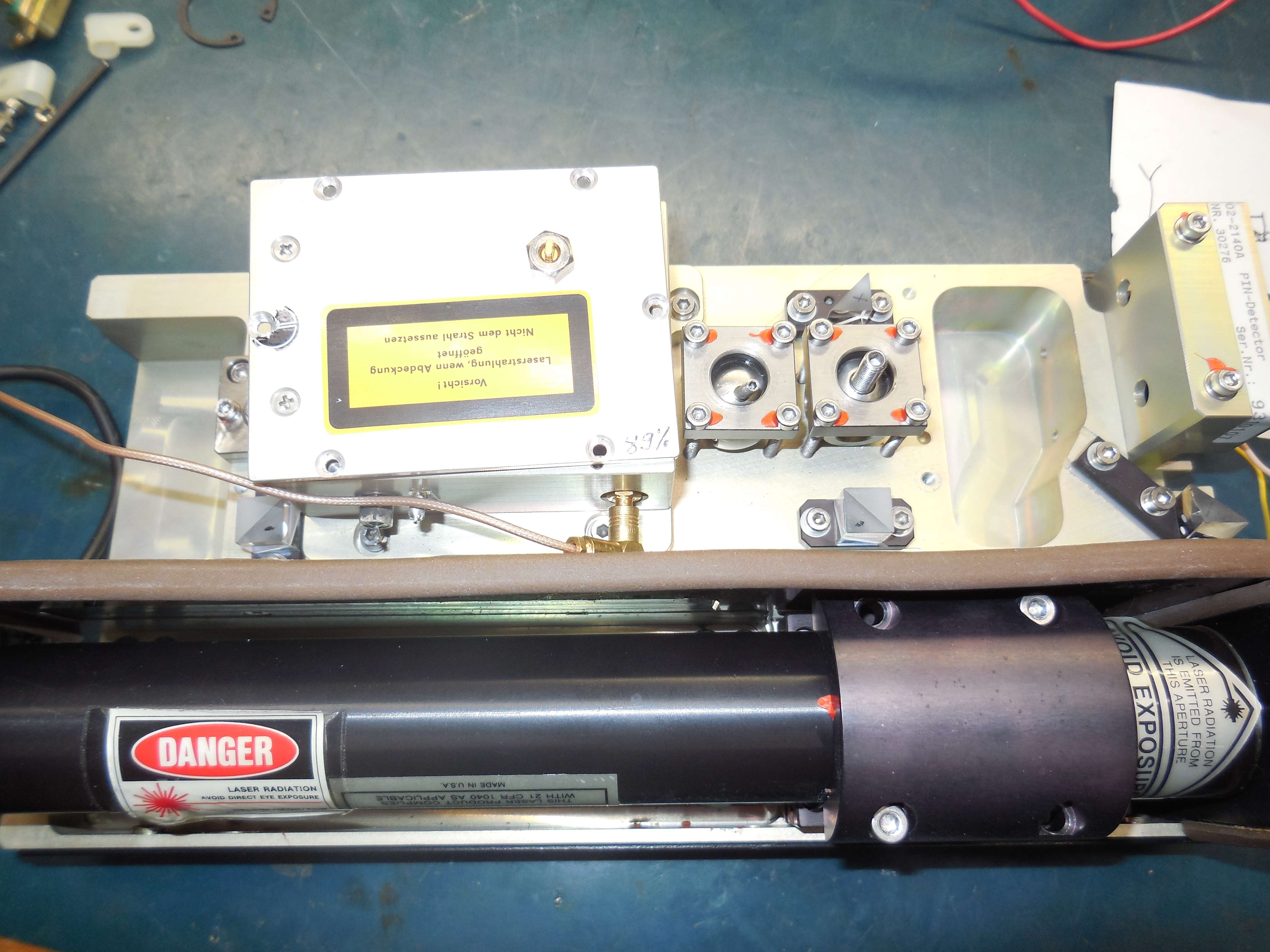
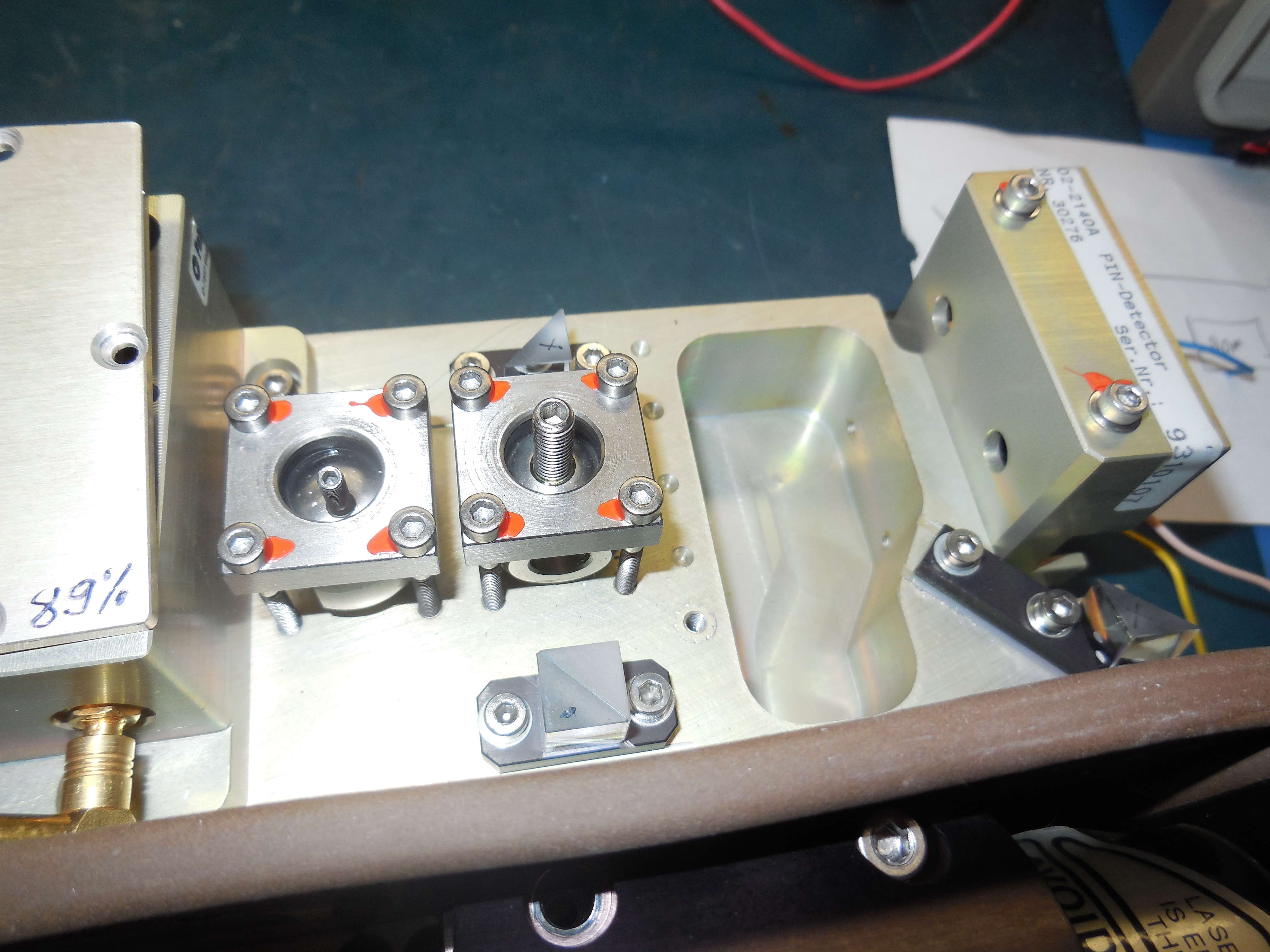
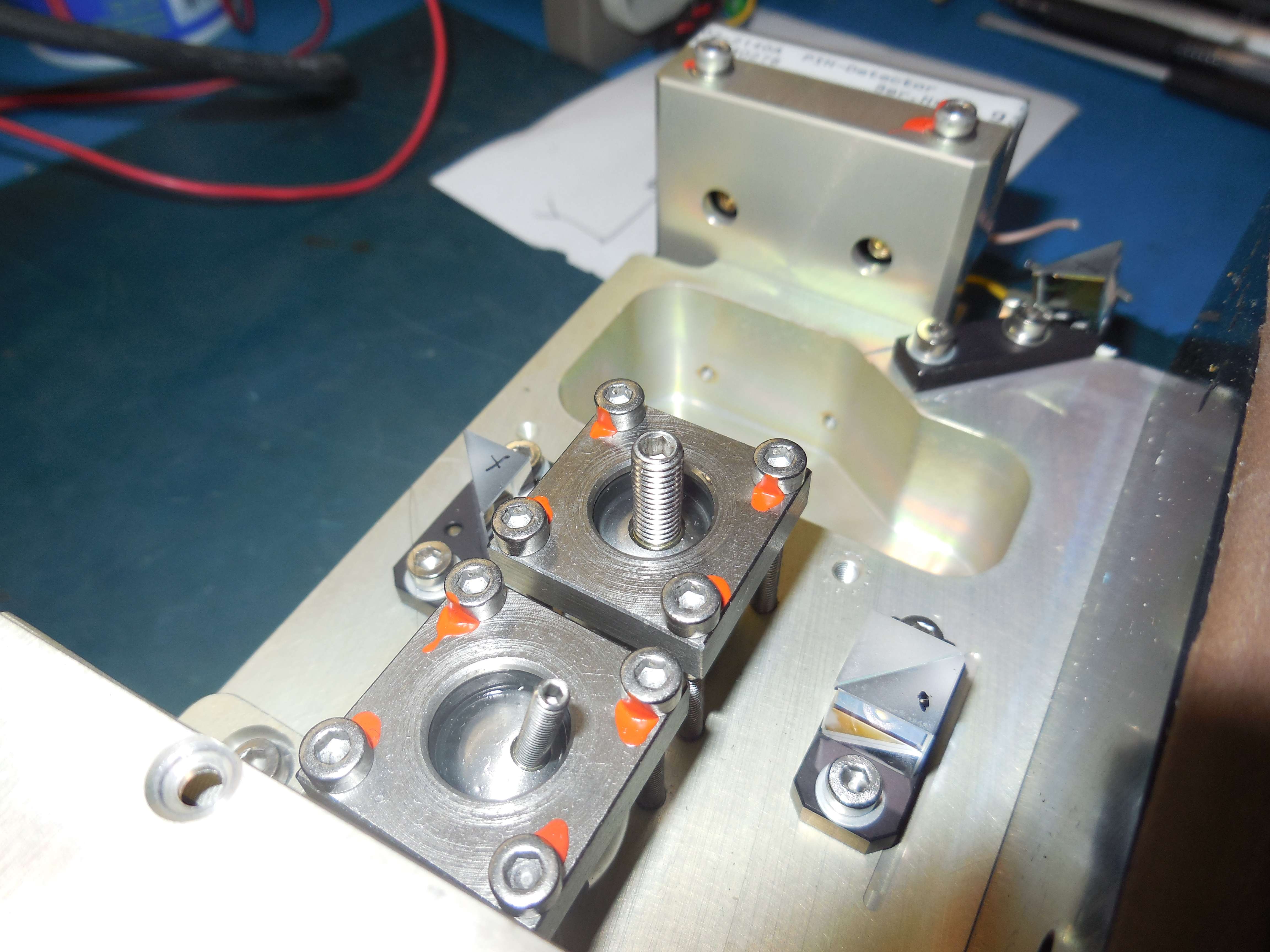
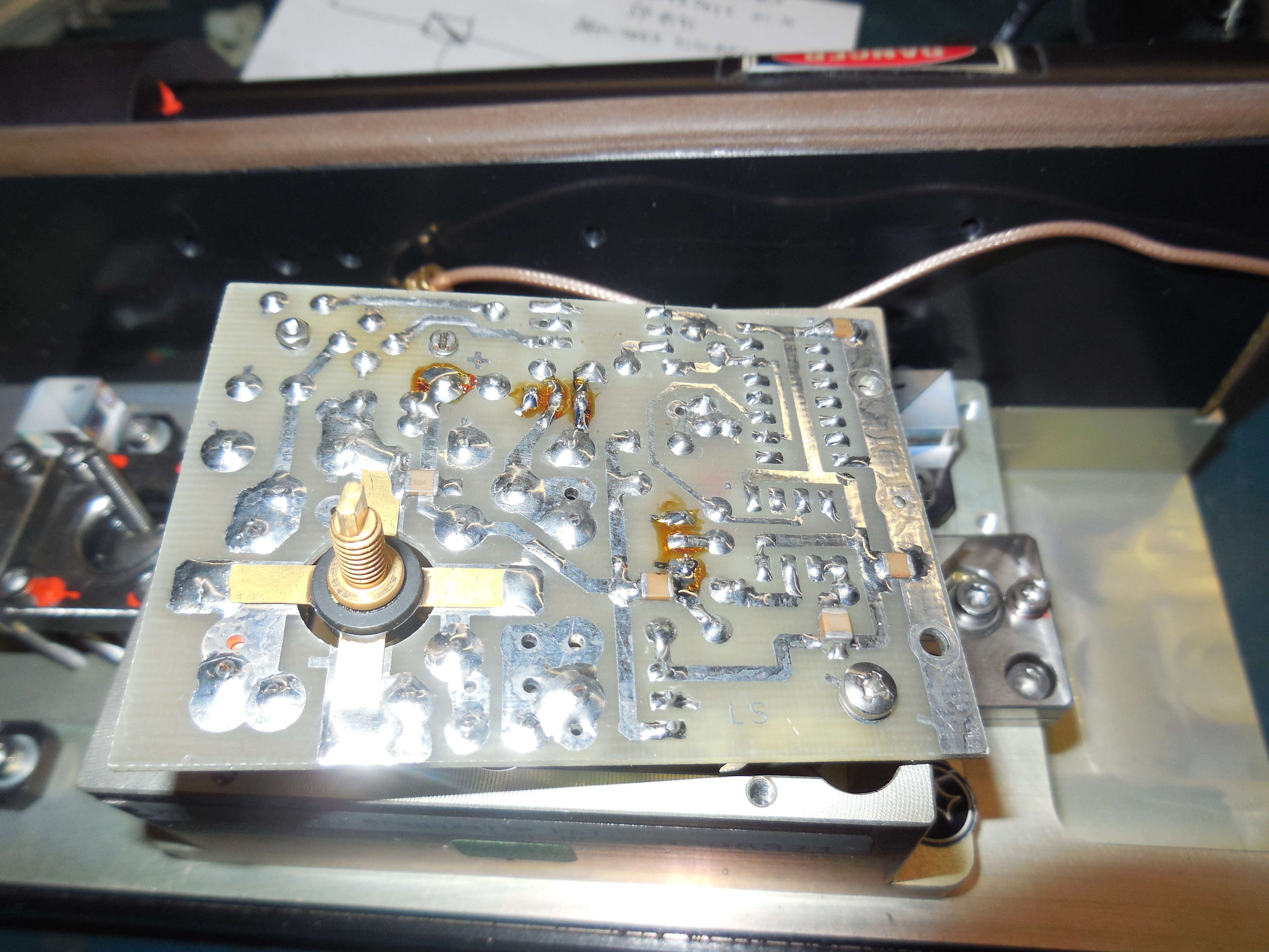
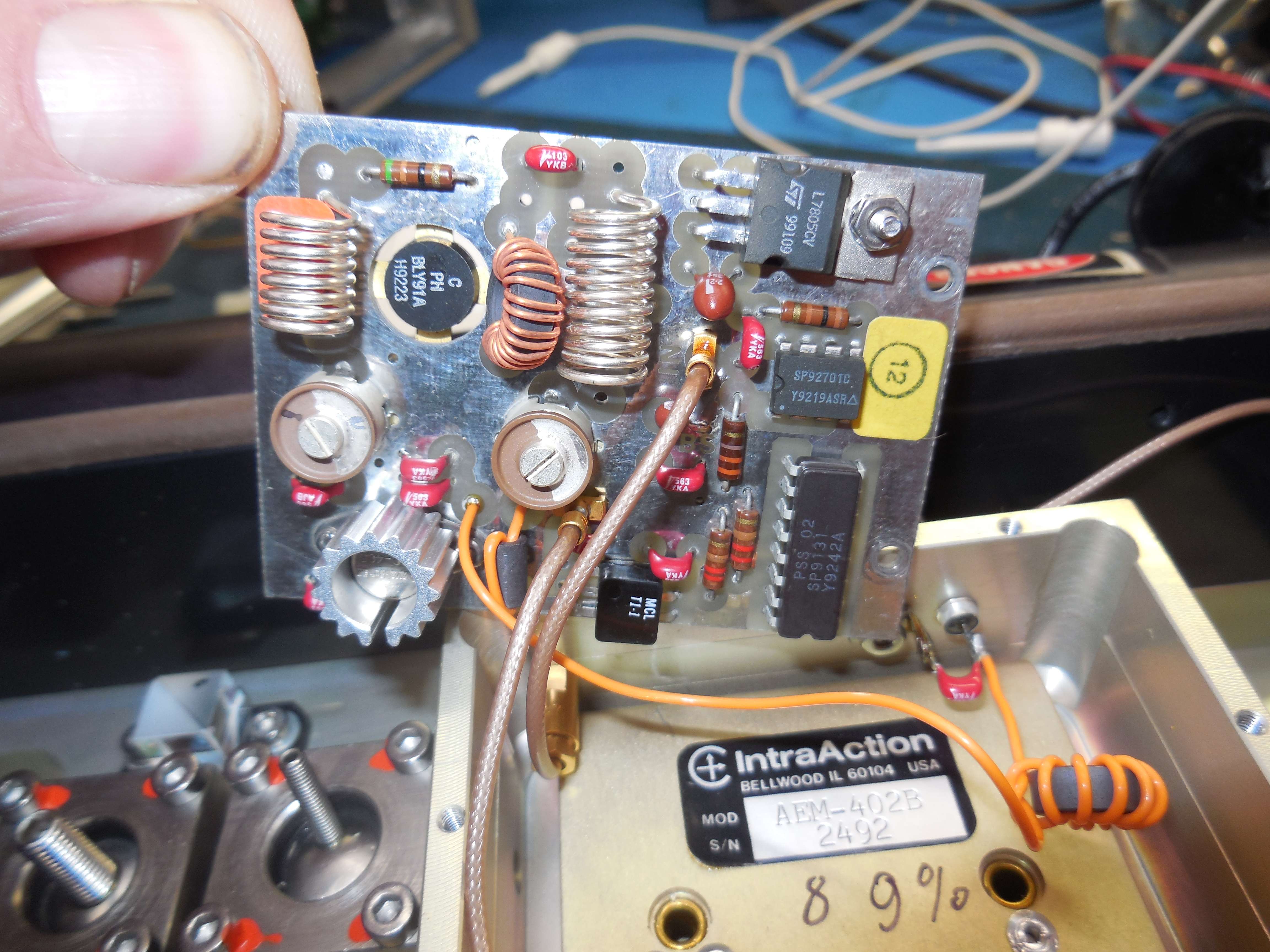


The Bragg AOM (VM302-2000A) requires an external 80 MHz source (+7 dBm or so). It has an internal divide-by-2 circuit (SP9131) and is powered by +15 VDC. The AOM itself is an IntraAction AEM-402B. The RF power amplifier section is based around an Avantek GPD and BLY91A transistor for about 2 watts output.
The laser source is Uniphase 1103P-2026 (2 mW, 633 nm).