| GBPPR Non-Linear Junction Detector |
| UNDER CONSTRUCTION |
Overview
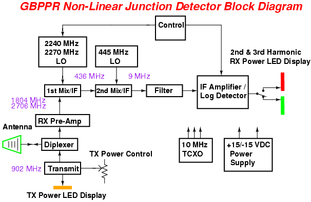
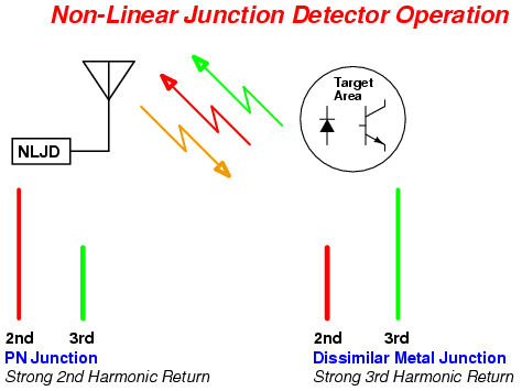
A Non-Linear Junction Detector (NLJD) is a counter-surveillance tool commonly used for detecting hidden transmitters or other electronic items. They work by transmitting a clean (no harmonics or audio modulation) 900 MHz RF signal at the target location and displaying the received signal strengths of the detected second (1800 MHz) and third (2700 MHz) harmonics. By comparing the received signal strengths of these two harmonics, the operator can distinguish if the target location contains a dissimilar metal non-linear junction, such as some rusty nails, or an actual P-N junction, such as a diode or transistor.
A "P-N junction" is the physical boundary area between the P-type and N-type semiconductor material used in the creation of our modern electrical components. By their nature, these boundary areas are "non-linear," meaning that when illuminated with a RF carrier they will generate successive harmonics of that initial illumination carrier signal. This harmonic generation is a function of the physical construction of the P-type and N-type boundary areas and doesn't even require the item to be powered on. In nature, a similar "P-N junction" is often created between two dissimilar metals and a catalyst. You've probably seen this in action as rust eating away on anything you've left outside for awhile. You can differentiate between a true semiconductor P-N junction and a "nature junction" by comparing the signal received signal strengths (and any modulations) of the different harmonics generated. True semiconductor P-N junctions tend to generate strong even harmonics (2nd, 4th, 6th, etc.), while dissimilar metals tend to create strong odd harmonics (3rd, 5th, 7th, etc.). Also, a harmonic signal from a true semiconductor P-N junction will be "quiet" when audio demodulated. Since the illumination RF carrier is clean and unmodulated, those even-order harmonics will also be clean and unmodulated. Compare this to the odd-order harmonics from dissimilar metals, which will tend to be "noisy" or "scratchy" when audio demodulated. If you've located a suspect area with your NLJD and hear "crackling noises" as you lighty pound around the area with a rubber mallet - you can be pretty sure it's just a dissimilar metal junction.
That's the idea at least, as I have no idea if the final project will work... The NLJD described here will be a bit clunky, but should be a good starting point for something more easily constructable and useable in the "real-world." The entire project will be built and documented as individual modules over a series of articles. This will allow for time to test and develop all the components for the project.
The main concept in a radio project of this type is isolation. You basically have a radio transmitter putting out around +30 dBm right next to a receiver trying to detect a harmonic which may be well below -100 dBm. The use of well-shielded module boxes, double-shielded coax, and high-quality RF connectors is highly recommended. I prefer using old California Amplifier MMDS downconverter cases. These cases are very well constructed, provide threaded holes (3/8"-32) for standard RF connectors, and can be had at very low cost - if you can find them! Most of the other parts for this project were scrouged from other electronic devices and surplus radio equipment found at ham radio swapfests, so some of the components may be rare or hard to find.
Feed-through capacitors should be used to route any non-RF signals in-or-out of the module boxes. This will prevent any excess leakage or RF interference. Voltage conditioning and regulation is not shown in the schematics, as it's all pretty standard. Try to use those new low-noise voltage regulators, though. Circuits with a PLL and VCO should each have their own dedicated voltage regulator to minimize interaction between them. Components in the pictures may vary from the schematics due to tweaking, but the schematics will have the correct values.
Block Diagrams
Pictures & Construction Notes
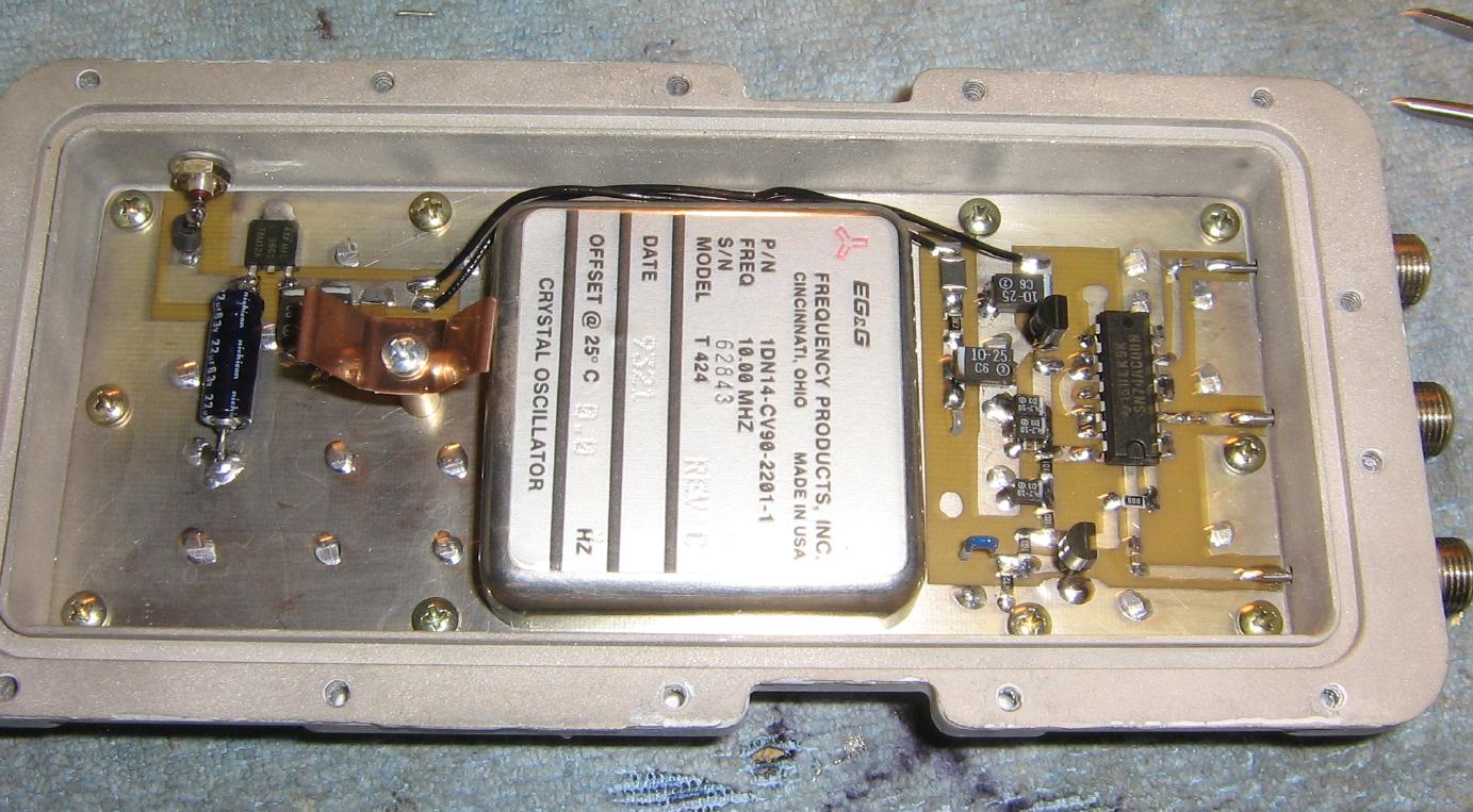
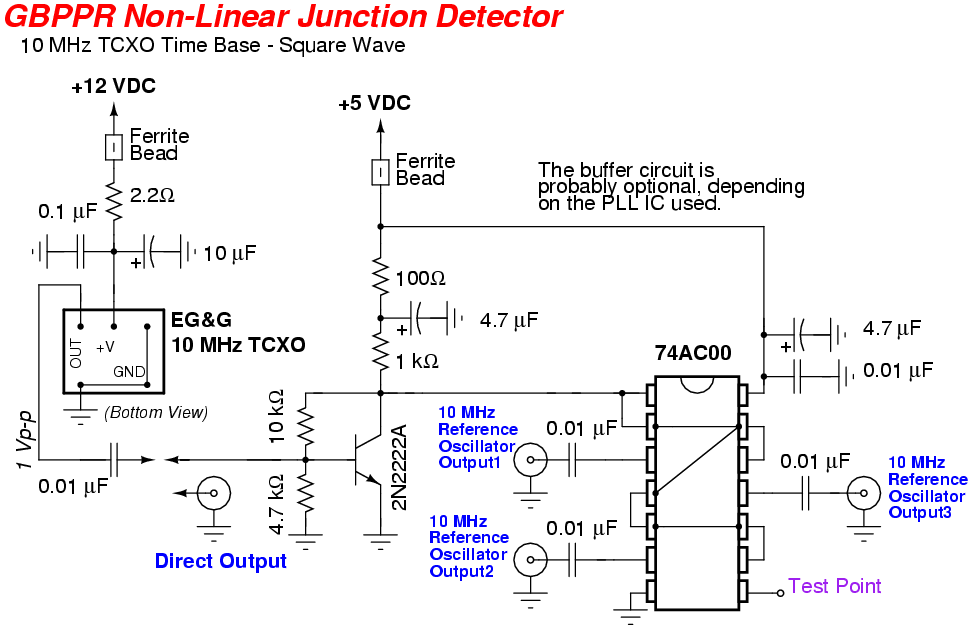
10 MHz Temperature Compensated Crystal Oscillator (TCXO) time base.
The 10 MHz TCXO is an EG&G Part Number 1DN14-CV90-2201-1 (Model Number T424), and is from an old Qualcomm OmniTRACS control unit.
Using an expensive TCXO like this is a bit of overkill, as just a regular 10 MHz crystal oscillator circuit will also work. Since both the transmitter and receiver frequency synthesizers will share the same time base, any frequency drift in the reference crystal should also track between those two circuits.
A simple 2N2222A transistor and 74AC00 buffer the 1 volt peak-to-peak output from the TCXO and convert it into a clean TTL-compatible square wave.
This may turn out to be a problem, as the harmonics generated by this time base extend all the way into the microwave spectrum. Without proper shielding, the time base could generate spurs on the frequency you wish to monitor - essentially jamming itself!
A filtered sine wave-based 10 MHz TCXO time base is currently under development. I'm also about 80% certain there is no need to even buffer the output from the TCXO, as most of the PLL synthesizer ICs have high-impedance reference frequency inputs.
The 10 MHz time base with have three reference outputs, provided via standard F jacks. One is for the transmitter, one is for the first local oscillator, and the other is for the second local oscillator.
Consider this time base design experimental, for now.
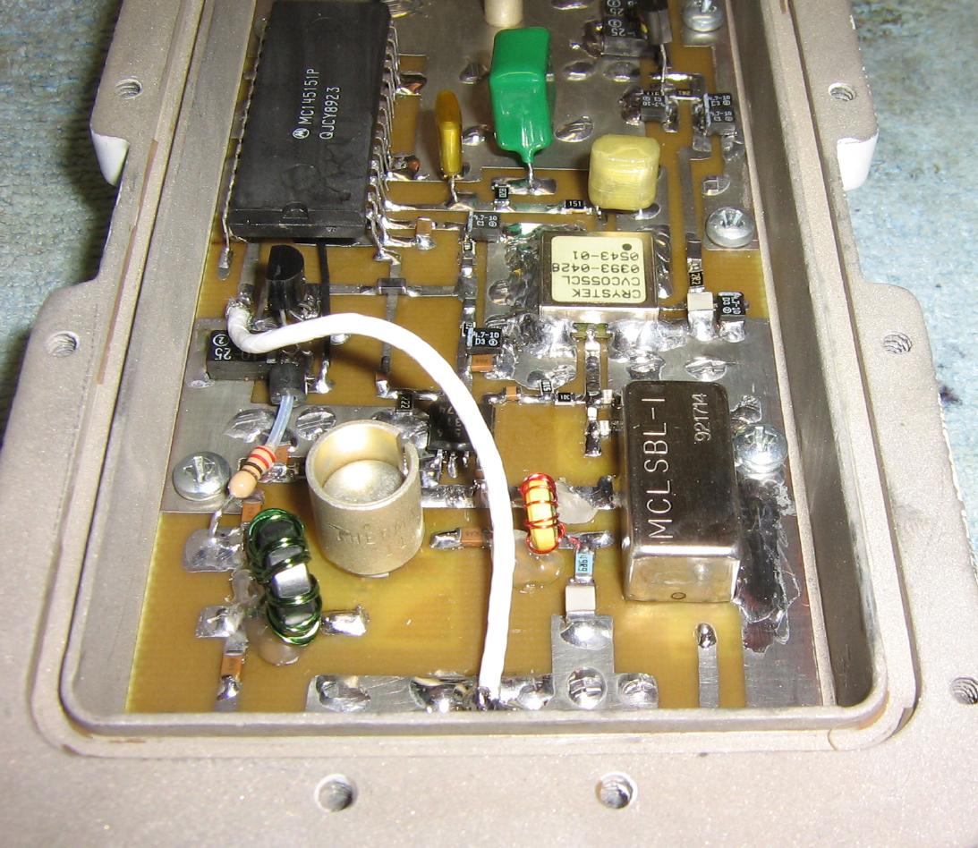
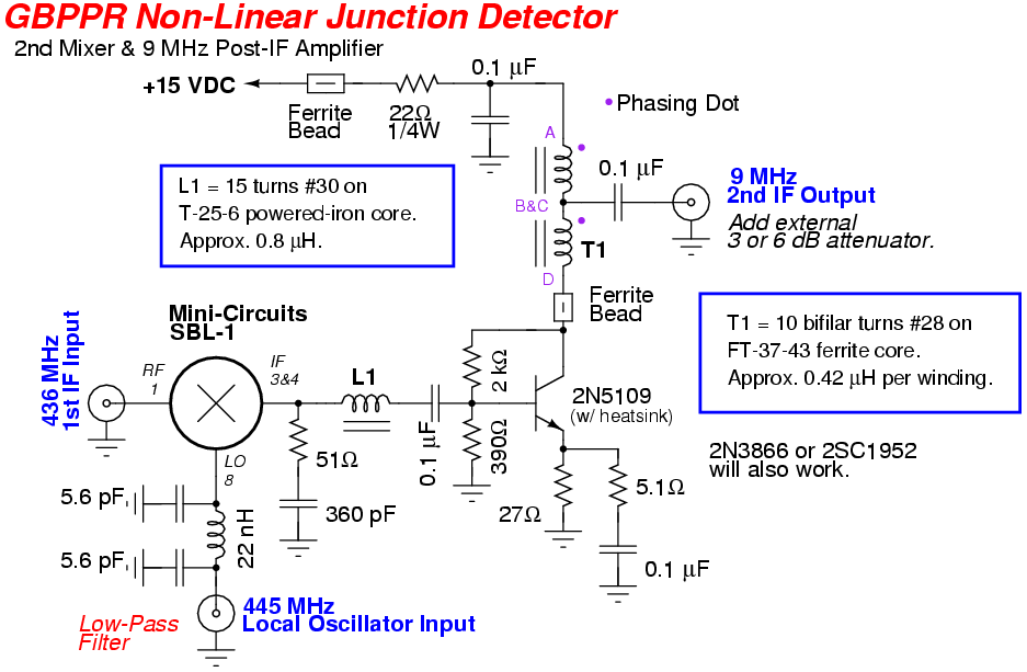
Overview of the second Local Oscillator (LO) and mixer.
This circuit converts the 436 MHz first Intermediate Frequency (IF) down to the 9 MHz second IF. It does this by mixing the incoming 436 MHz RF signal with a local oscillator frequency of 445 MHz. The mixing takes place in a Mini-Circuits SBL-1 mixer.
A high-dynamic range post-mixer 9 MHz IF amplifier helps to recover some of the power lossed through the mixer. It also provides the first bit of final filtering via the low-pass diplexer circuit.
The yellow toroid is approximately 0.8 µH and consists of 15 turns of #30 enameled magnet wire on a T-25-6 powered-iron core.
The other toroid forms a 4:1 matching transformer to convert the 200 ohm output impedance of the 2N5109 down to 50 ohms. It consists of ten bifilar (twisted together) turns of #28 enameled magnet wire on a FT-37-43 ferrite core. Each winding measured around 0.42 µH. Be sure to keep track of the phasing when winding the core.
Here's a list of spurs (under 1 GHz) generated by this circuit with a -30 dBm input at 436 MHz:
10 MHz intervals from reference clock into the high-UHF range, -50 dBm max.
9 MHz intervals from the IF output, falls off after 45 MHz.
881 MHz, -75 dBm  (436 MHz RF input + 445 MHz LO)
890 MHz, -74 dBm  (2 * 445 MHz LO)
899 MHz, -84 dBm  (2 * 445 MHz LO + 9 MHz IF)
445 MHz, -70 dBm  (LO leakage)
436 MHz, -92 dBm  (RF input leakage)
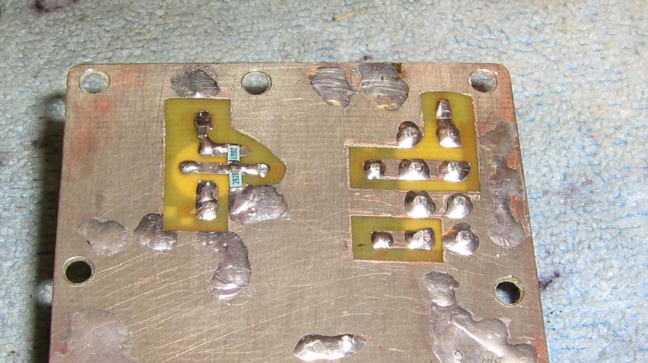
The PC board was made via a "psuedo double-sided" technique.
In order to reduce the height of the Mini-Circuits SBL-1 mixer and 2N5109 transistor, the PC board was drilled to pass the component's leads through. Then little extension pads where added to connect back up to the top side of the board via small connecting wires.
This also helps to give the final circuit additional isolation as any RF leakage is trapped underneath the circuit board.
Bifilar-Wound Toroid
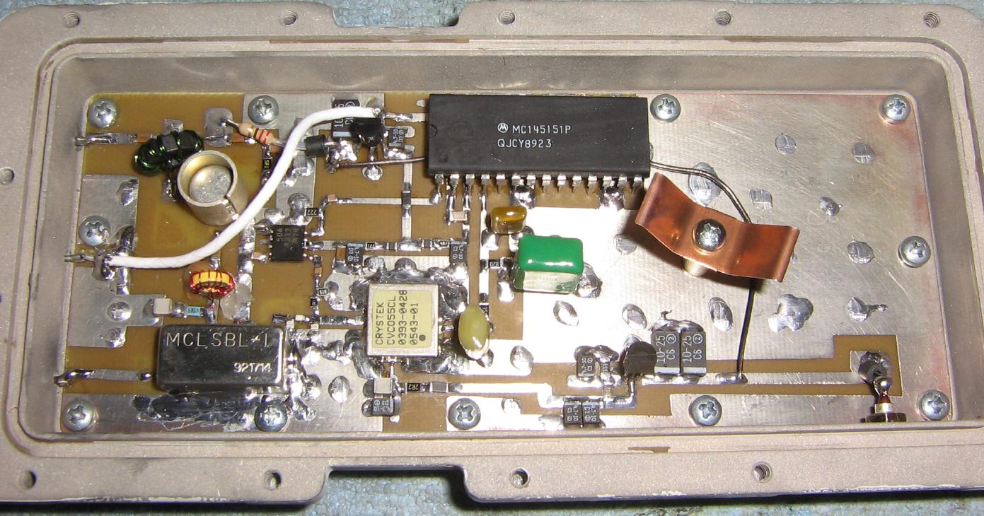
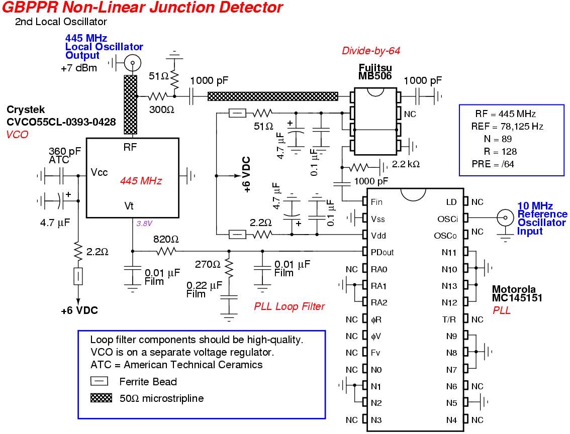
The 445 MHz local oscillator is created by a PLL frequency synthesizer circuit using a Motorola MC145151 synthesizer IC and a Crystek CVCO55CL-0393-0428 Voltage Controlled Oscillator (VCO).
The Crystek CVCO55CL-0393-0428 isn't ideal for this circuit, as its stock RF output power is a little low (+3 dBm), but I had one available from another project and they are available from Mouser. We'll run the VCO at +6 VDC in order to help bump up the output RF power a few dBms.
The components which make up the PLL loop filter itself should be of high-quality and low-leakage to minimize the generation of microphonics or excess carrier sideband noise. Try to use 1% metal-film resistors and non-polarized polystyrene or other film capacitors.
A 3 or 6 dB resistive attenuator pad should be added to the 9 MHz output of this circuit to help the mixer and 2N5109 "see" a 50 ohm impedance. This also helps to tame the high-impedance of the resolution filter down line.
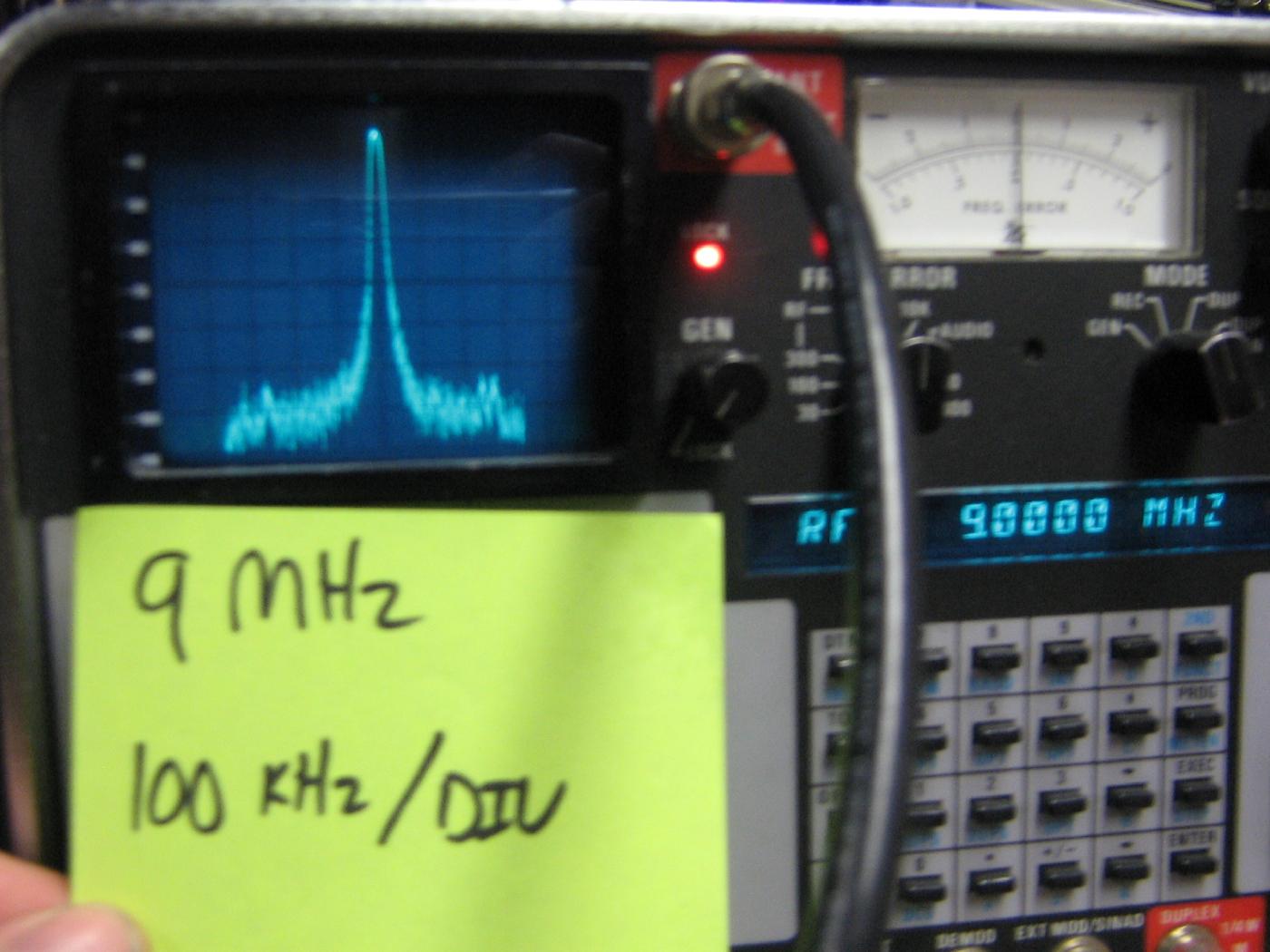
Spectrum analyzer view of the 9 MHz second IF output with a -30 dBm 436 MHz RF input signal.
9 MHz center display with 100 kHz per horizontal division and 10 dB per vertical division.
No major spurs were found.
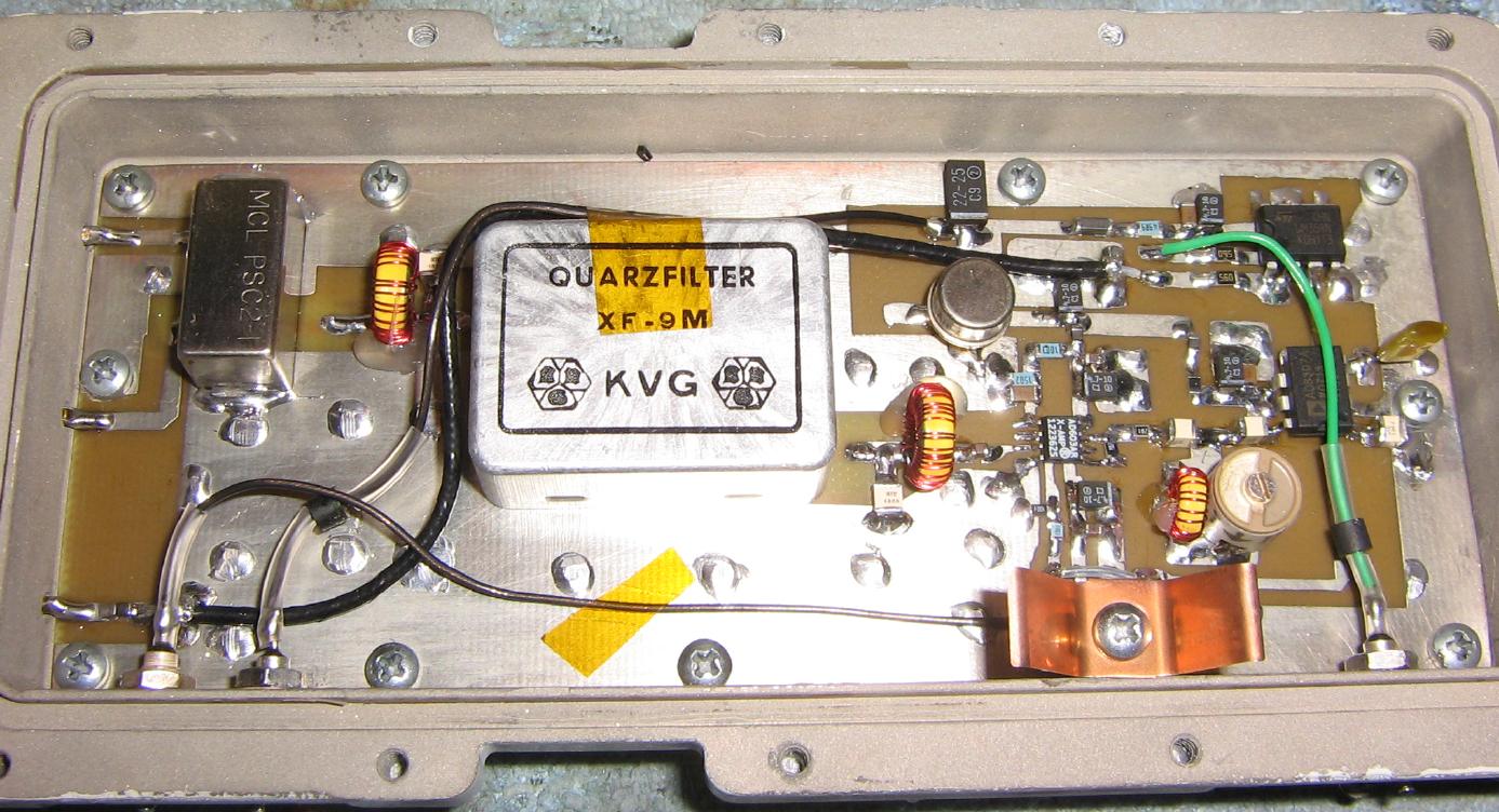
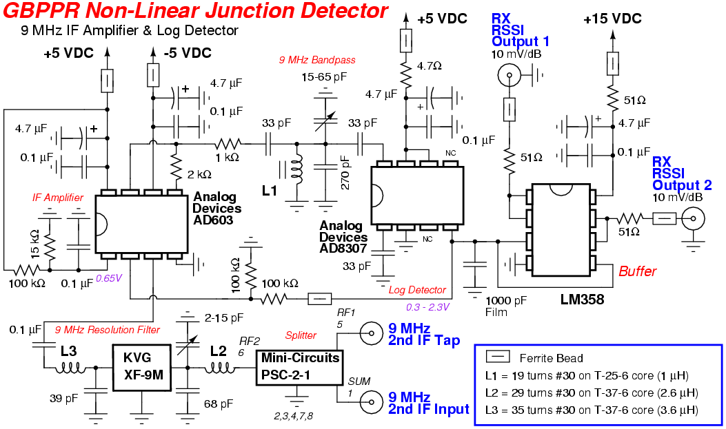
Overview of the 9 MHz resolution filter, 9 MHz final IF amplifier, and the logarithmic detector.
The 9 MHz input from the second mixer is on the upper-left and is split via an optional Mini-Circuits PSC-2-1 RF splitter. One of the ports on the splitter continues onto the resolution filter and the other will go to a front-panel BNC connector for external processing.
The 9 MHz resolution filter shown here is a KVG XF-9M crystal filter with a bandwidth of 500 Hz. These filters were all the rage in amateur radio about 30 years ago, and may be difficult to find today. There are homebrew drop-in replacements for 9 MHz filters with the same basic specifications available from time-to-time on eBay.
The final Received Signal Strength Indicator (RSSI) voltage output from the Analog Devices AD8307 is on the bottom-left via a BNC jack.
The output from the resolution filter is then sent to a combination Analog Devices AD603 / AD8307 IF amplifier and logarithmic detector. This circuit is straight from the AD8307's datasheet (Figure 40 - 120 dB Measurement System), with only a few minor tweaks.
It's total overkill, but the AD603 / AD8307 combination work amazingly well together for only around $20 in parts. Most commercial (and government) NLJD IF/log detector strips are based around common FM receiver ICs and tend to have a poor dynamic range.
KVG XF-9M 9 MHz Crystal Filter Specifications
        6 dB Bandwidth: 500 Hz (CW)
        Insertion Loss: 5 dB / 1 dB ripple
Input/Output Impedance: 500 ohms / 30 pF
          Shape Factor: 6:40 dB 2.5
                        6:60 dB 4.4
  Stopband Attenuation: 90 dB
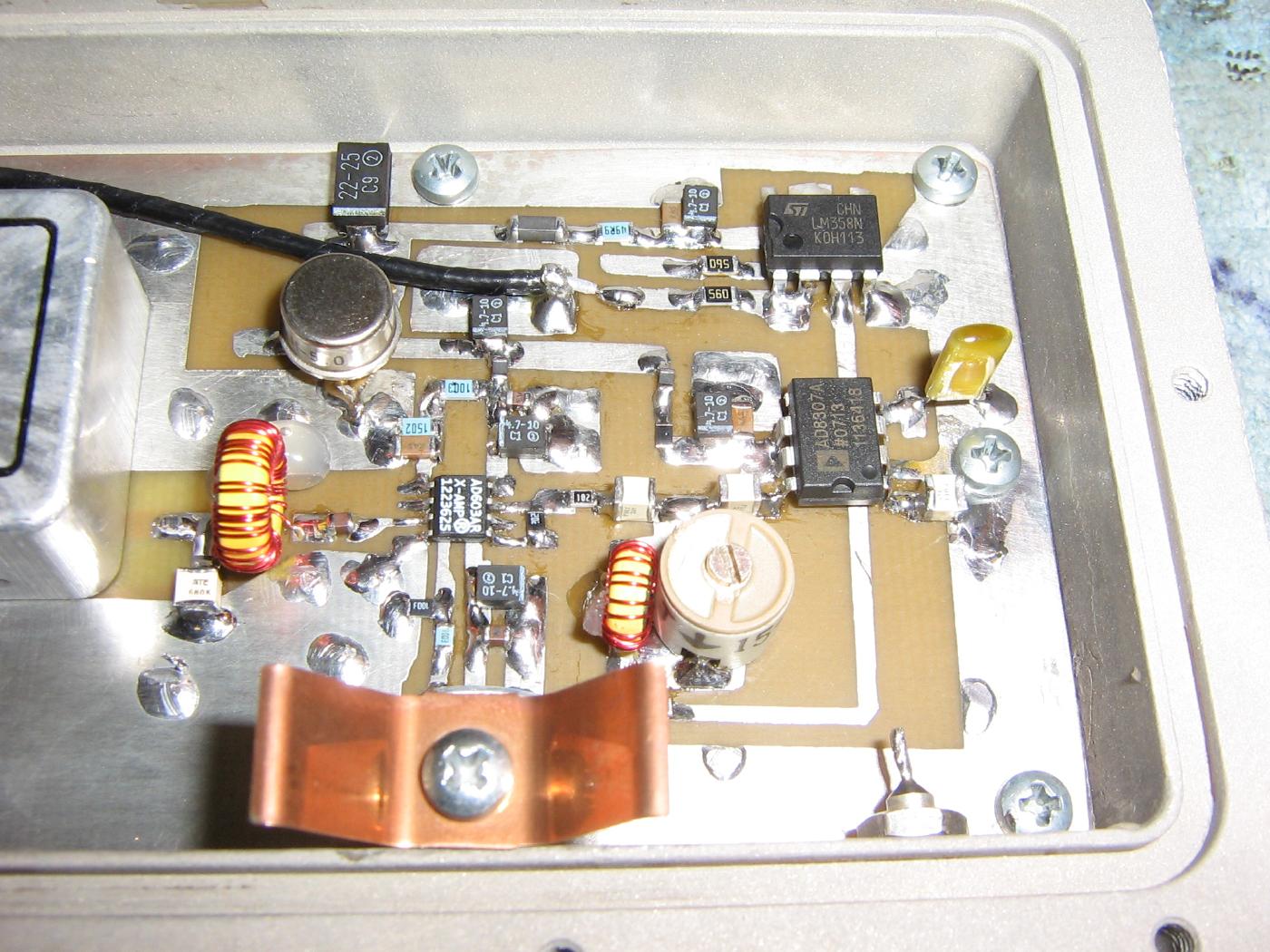
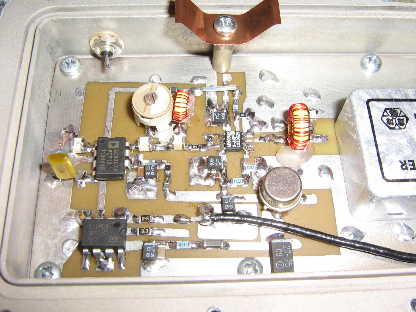
Closeup view of the Analog Devices AD603 and AD8307. The RSSI DC voltage output from the AD8307 is buffered by a LM358 op-amp.
A simple little L/C filter helps to knocks down any excess spurs before entering the AD8307. Inject a low-level 9 MHz signal and tune for a "peak" to adjust this filter.
The output from the AD8307 controls the gain of the AD603. This keeps the entire circuit from being over-driven and provides a response from at least -100 dBm to over +10 dBm.
The Analog Devices AD603 does require a -5 VDC power supply, but with a minimal current draw.
Alternate view.
Try to keep the +5 VDC power line well-regulated and use 1% metal-film resistors in the voltage dividers.
Here is a chart for various power levels (at 9 MHz) input to the final NLJD IF amplifier/log detector circuit:
Input RF Level (dBm)       RX RSSI Output (Volts)
No RF                      0.43
-100                       0.44
-90                        0.46
-80                        0.55
-70                        0.70
-60                        0.87
-50                        1.02
-40                        1.20
-30                        1.35
-20                        1.53
-10                        1.72
0                          1.86
+10                        2.04
These values are subject to change as I fiddle with the overall design. The impedance matching to the KVG filter may need a little tweaking, which will effect the final value. The actual voltage level isn't important, just that it changes properly as the input RF power level also changes.
Schematics
- 10 MHz Temperature Controlled Crystal Oscillator - Square Wave
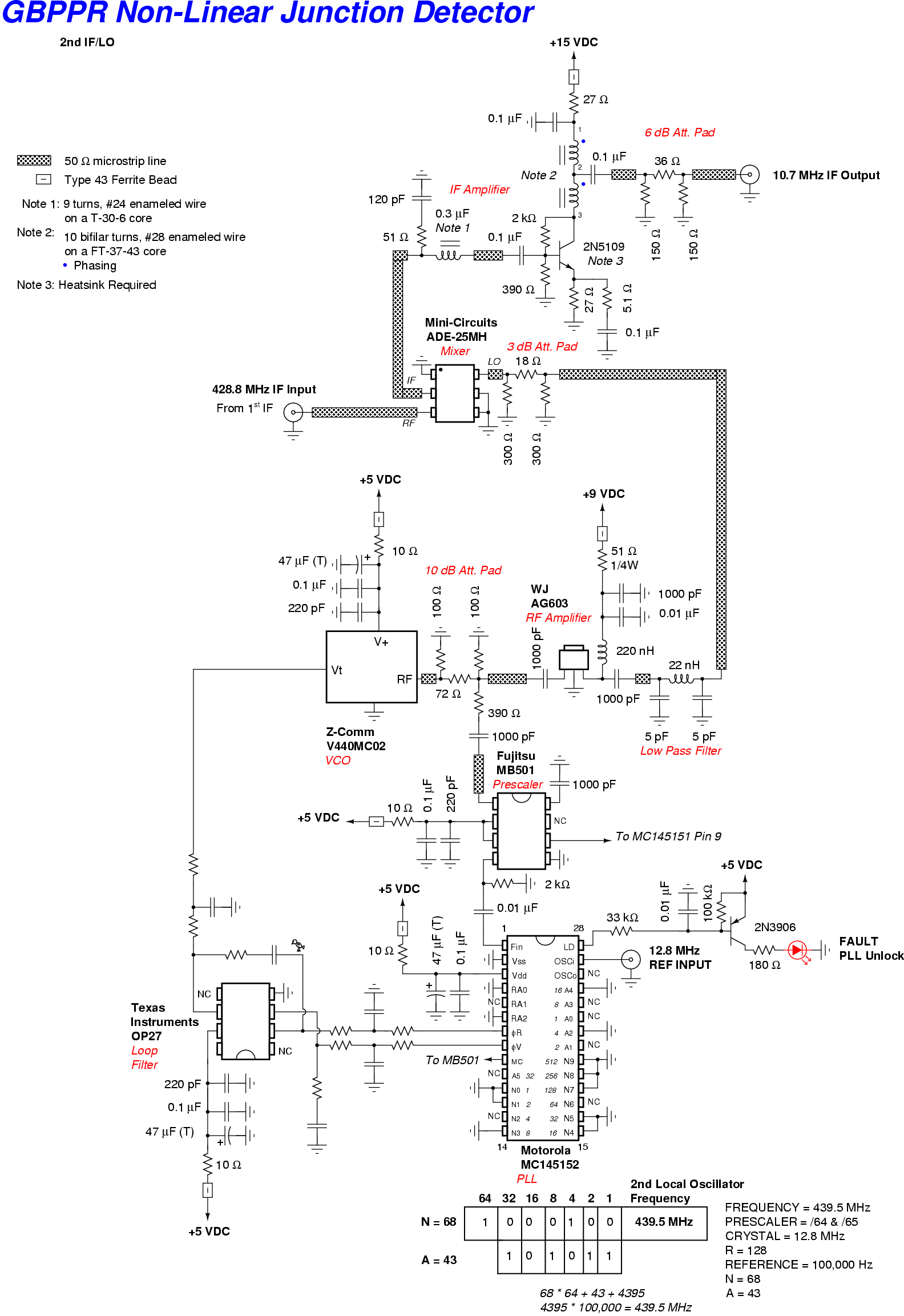
- 2nd Local Oscillator
- 2nd Mixer & 9 MHz Post-IF Amplifier
- 9 MHz IF Amplifier & Logarithmic Detector
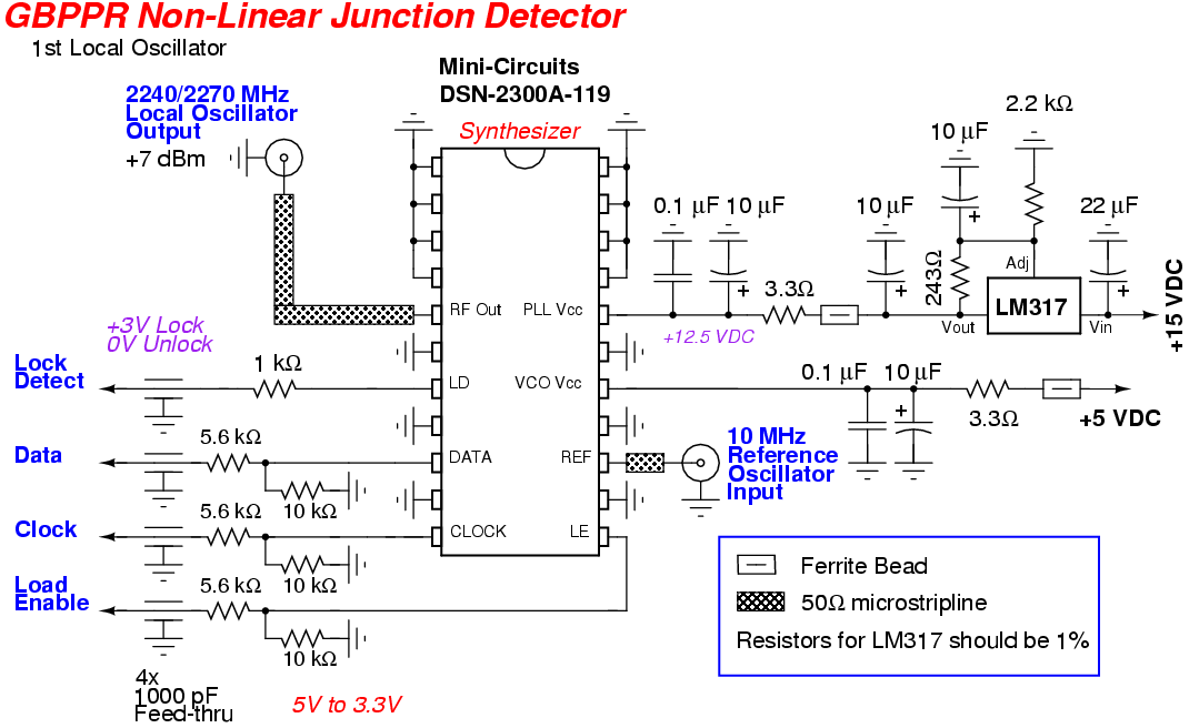
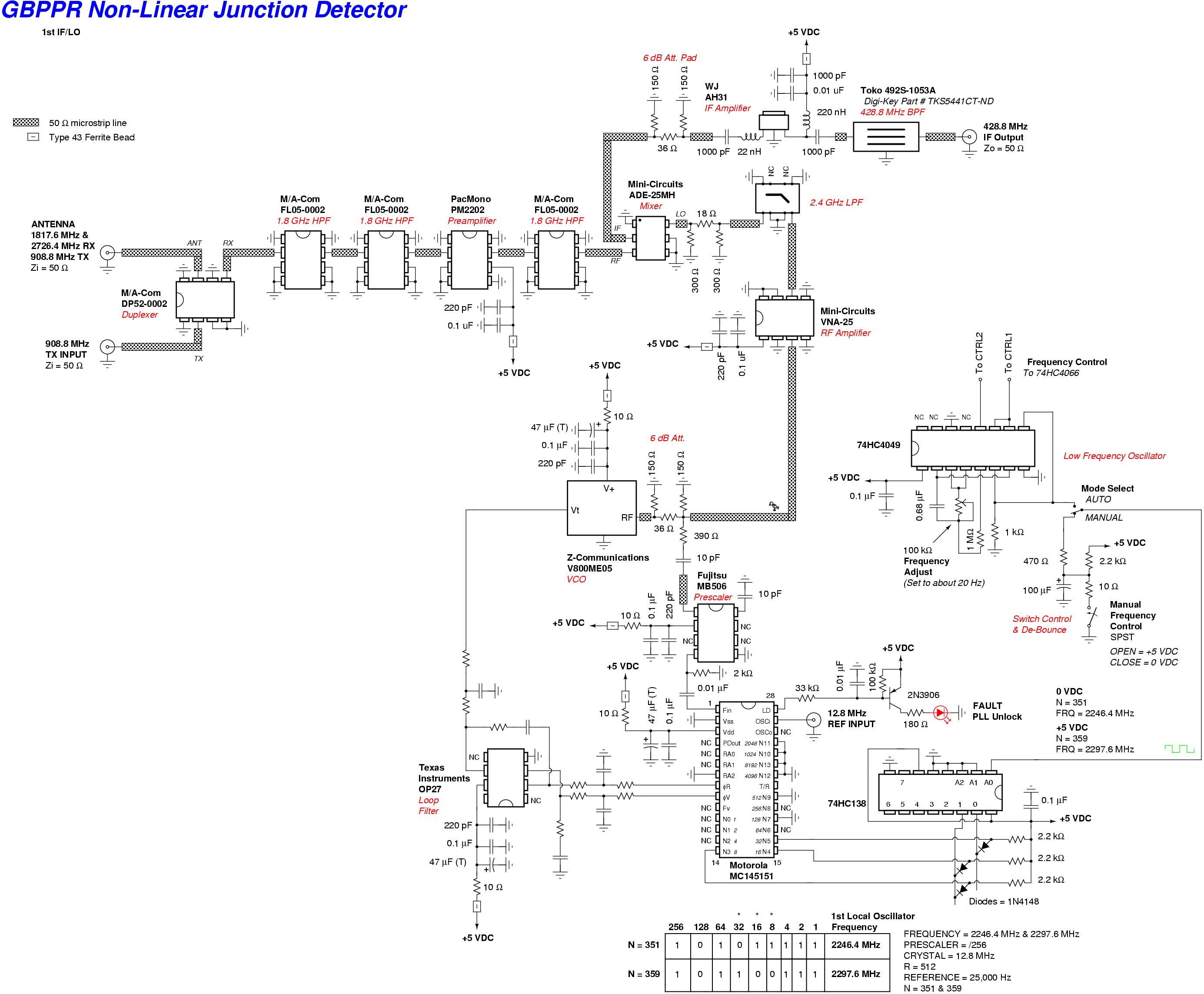
- 1st Local Oscillator
- 1st Mixer & 436 MHz Post-IF Amplifier
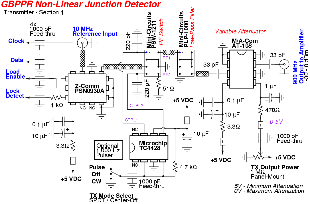
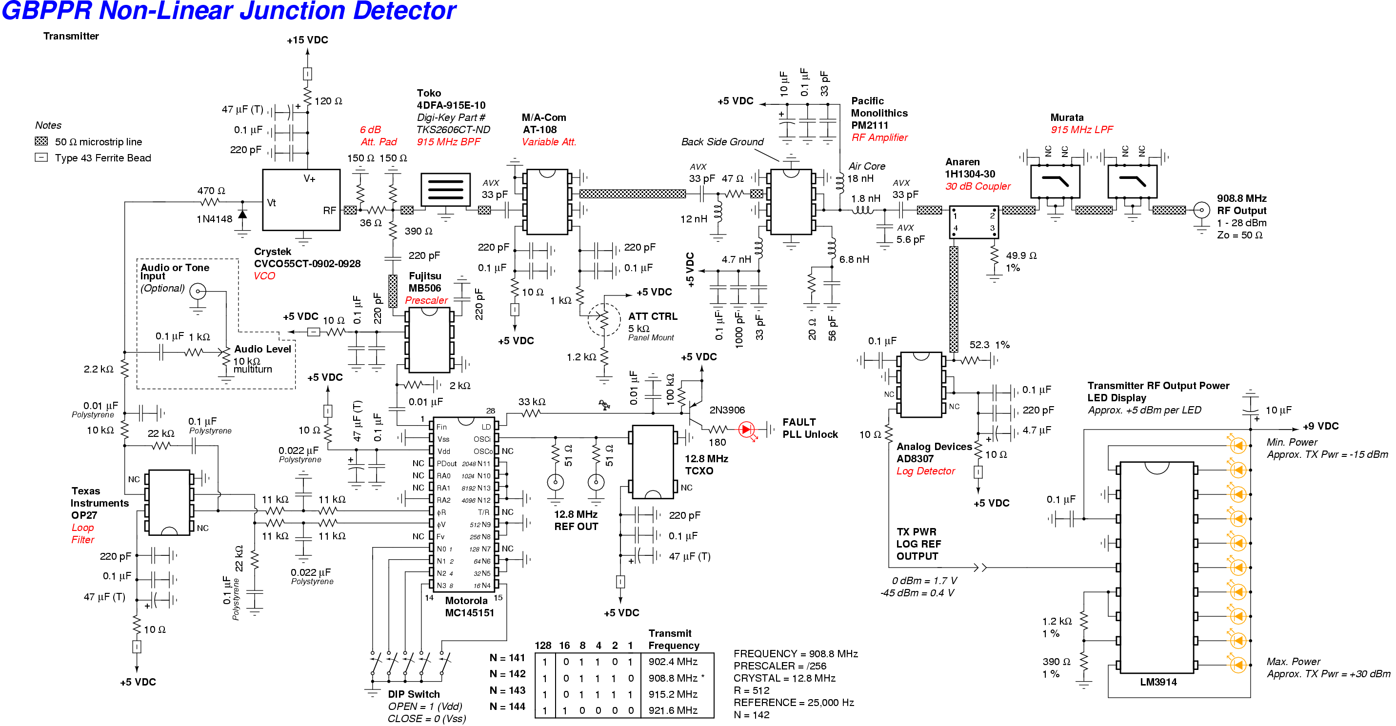
- Transmitter - Section 1
- Transmitter - Section 2
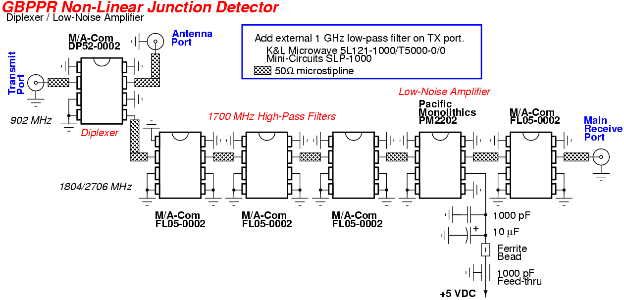
- Diplexer & Low-Noise Amplifier
Old Design - Reference Only
Datasheets
- Mini-Circuits SBL-1 Mixer (280k PDF
- Mini-Circuits SRA-3500 Mixer (284k PDF
- Mini-Circuits PSC-2-1 RF Splitter/Combiner (223k PDF
- Mini-Circuits PSW-1211 PIN Diode RF Switch (129k PDF)
- Mini-Circuits PLP-1000 1000 MHz Low-Pass Filter (184k PDF)
- Crystek CVCO55CL-0393-0428 393-428 MHz VCO (154k PDF)
- Pacific Monolithics PM2111 RF Power Amplifier (947k PDF)
- Pacific Monolithics PM2202 Low-Noise Amplifier (648k PDF)
- Fujitsu MB506 UHF Prescaler (65k PDF)
- M/A-Com AT-108 Voltage Variable Absorptive Attenuator (47k PDF)
- M/A-Com FL05-0002 1700 MHz High-Pass Filter (53k PDF)
- M/A-Com DP52-0002 Dual-Band Diplexer (146k PDF)
- WJ Communications/TriQuint AH31 High-Dynamic Range IF Amplifier (267k PDF)
- Toko 492S-1055A Filter (53k PDF)
- Microchip TC4428 Dual High-Speed Power MOSFET Driver (441k PDF)
- Analog Devices AD603 IF Amplifier (241k PDF)
- Analog Devices AD8307 Logarithmic Amplifier/Detector (403k PDF)
- LM3914 LED Display Driver (375k PDF)
- MC145151 / MC145152 PLL Frequency Synthesizer (444k PDF)
- National LMX2316 PLL Frequency Synthesizer (409k PDF)
- Analog Devices ADF4106 PLL Frequency Synthesizer (303k PDF)
- LM358 Low-Power Dual Op-Amp (1M PDF)
- Anaren 1H1304-30 30 dB 800-1000 MHz Directional Coupler (83k PDF)
- Z-Comm PSN0930A 900-960 MHz Frequency Synthesizer Module (84k PDF)
- Mini-Circuits DSN-2300A-1119+ 1690-2310 MHz Frequency Synthesizer Module (843k PDF)
Notes & Links
- Higher resolution pictures and the original project article are available in GBPPR 'Zine Issue #91 and Issue #93
- Non-Linear Junction Detector Repository contains codes, block diagrams, and other important files related to the Non-Linear Junction Detector, build as part of the Electronic Design Lab at EE (IIT Bombay), by Debarnab Mitra, Prakirt Jhunjhunwala, and Varunesh Goyal
- LimeSDR NLJD The software-based NLJD works by transmitting a clean, unmodulated RF signal at the target location and analyzing the received signal strengths of the detected second and third harmonics. By comparing the received signal strengths of these two harmonics, the operator can determine if the target location contains a dissimilar metal non-linear junction, such as rusty nails, or an actual P-N junction, like a diode or transistor, by Ma5onic
- Non-Linear Junction Characterization by M.R. McMillan, Defence Research Establishment Ottawa, Technical Note No. 79-7
- Wideband Harmonic Radar Detection by Farrukh Aslam, S. M. (2008), Durham theses, Durham University.
- Non-Linear Junction Detector Review and Tutorial by James Atkinson
- About Non Linear Junction Detectors by Waypoint Counter Surveillance
- Research Electronics International NJE-4000 "ORION" NLJD Very popular commercial NLJD. Note that REI has been engaging in some very illegal activity against James M. Atkinson.
- Orion 900 - Internal Photos
- Orion 900 - FCC Test Report
- Orion 2.4 - Internal Photos
- Orion 2.4 - User Manual v1.2
- Orion HX - User Manual v2.4
- Overview of the NJE-4000 "ORION" NLJD by James Atkinson
- Review of the REI NJE-4000 "ORION" NLJD by Fuller Group Security
- Marty Kaiser 4059C Diviner NLJD
- Winkelmann HAWK 450 XD NLJD (250k PDF)
- Bahia 21 RFD 23 NLJD (162k PDF)
- Audiotel SuperBroom NLJD
- SuperBroom Plus TA - User Manual
- Audiotel SuperBroom Plus TA via Crypto Museum
- Audiotel Scanlock Broom ECM via Crypto Museum
- Picture 1
- Picture 2
- Picture 3
- Lornet 36 NLJD From Russia. Operates at 3.6 GHz and fairly high RF output power.
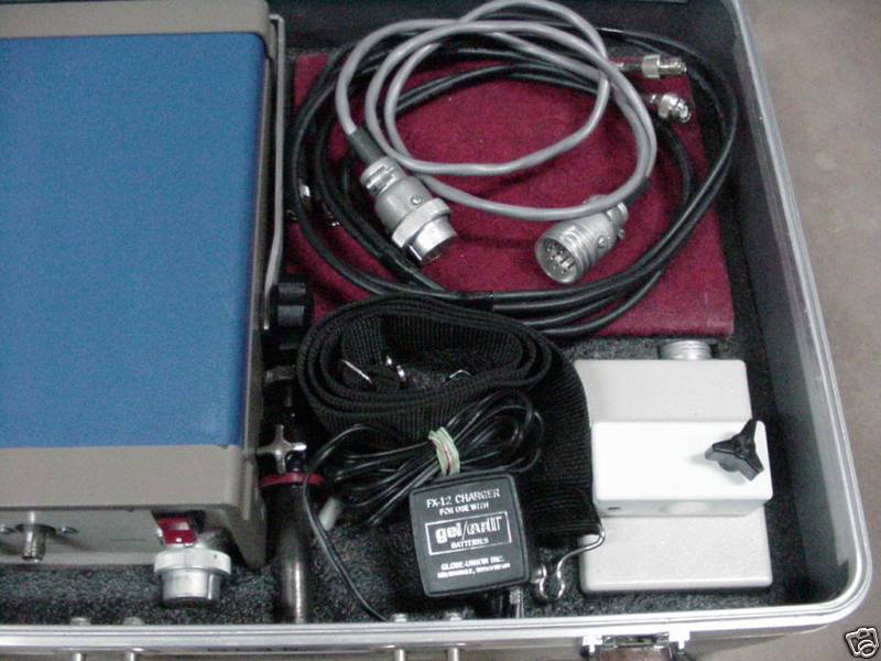
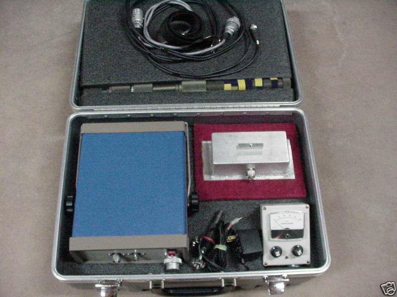
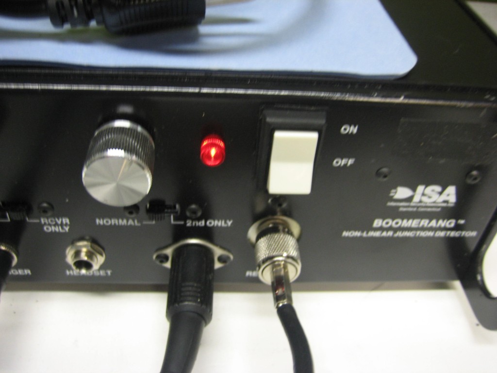
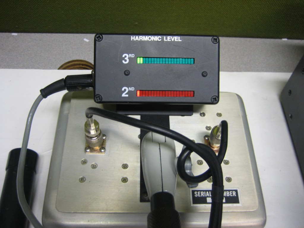
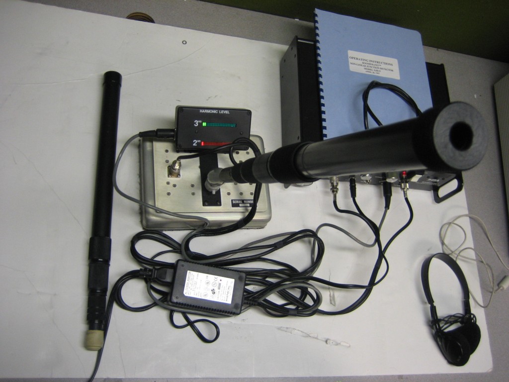
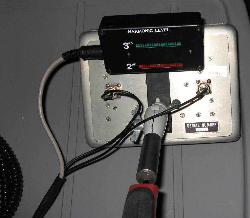
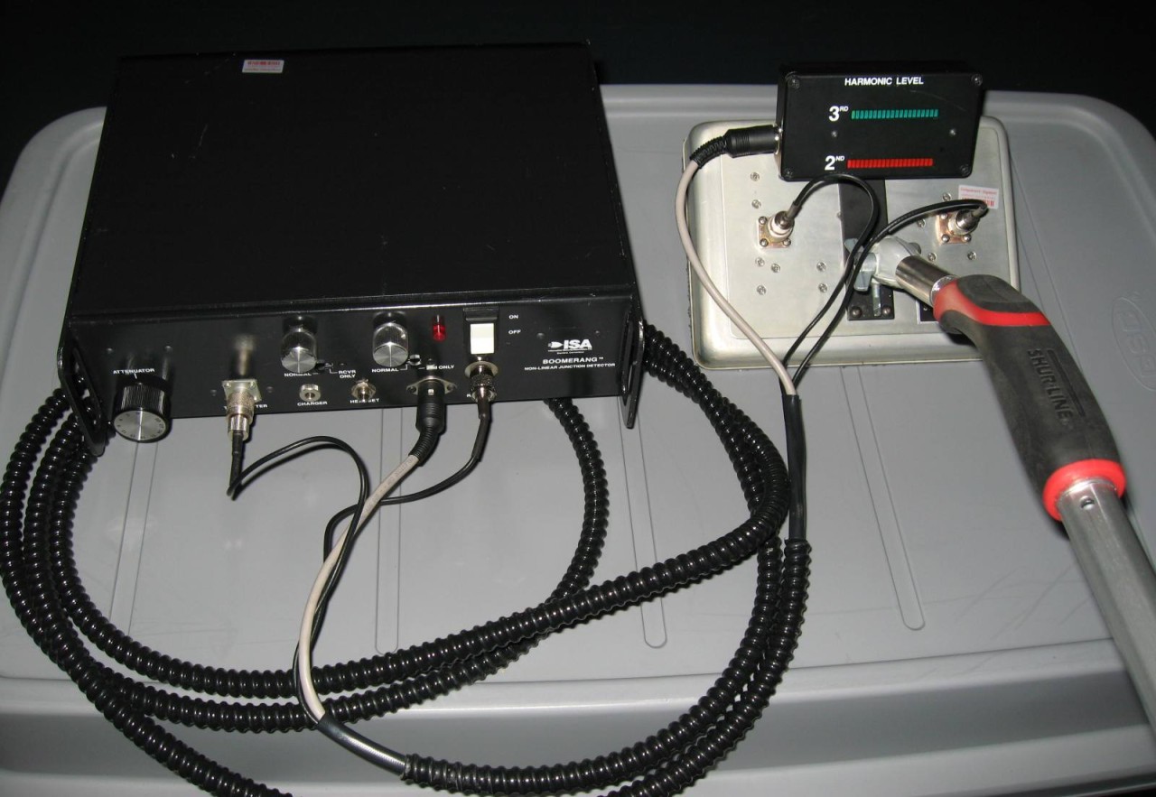
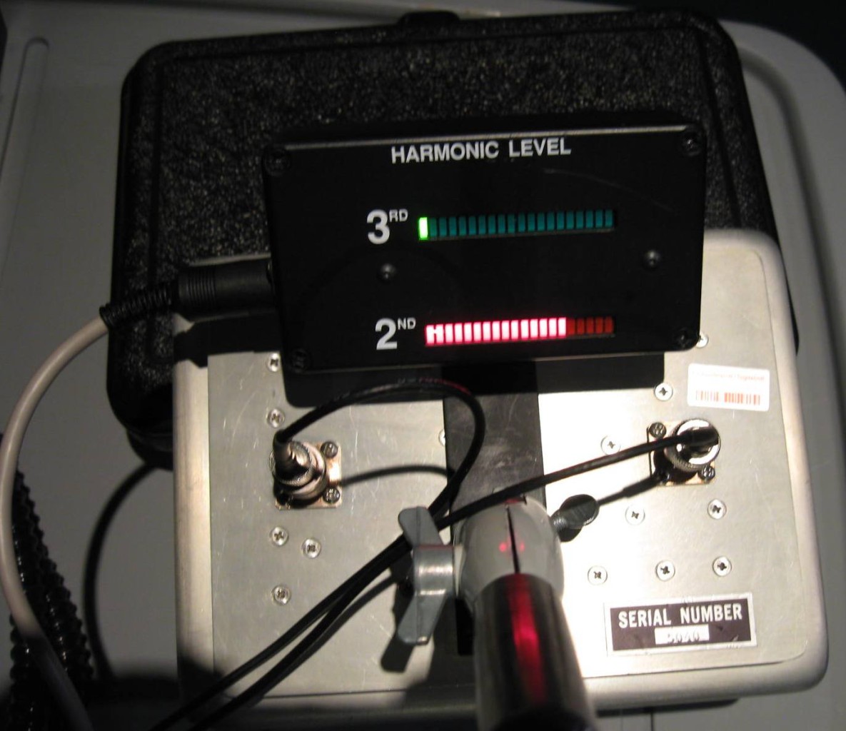
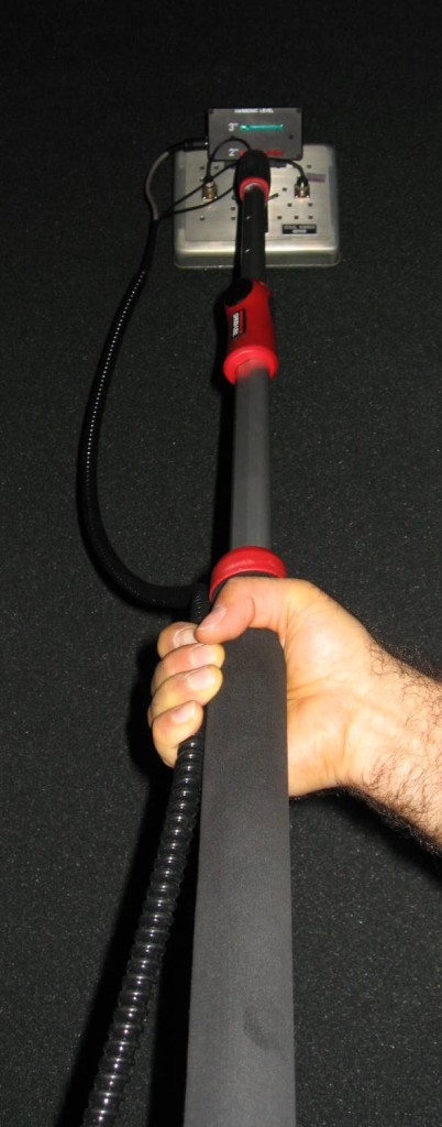
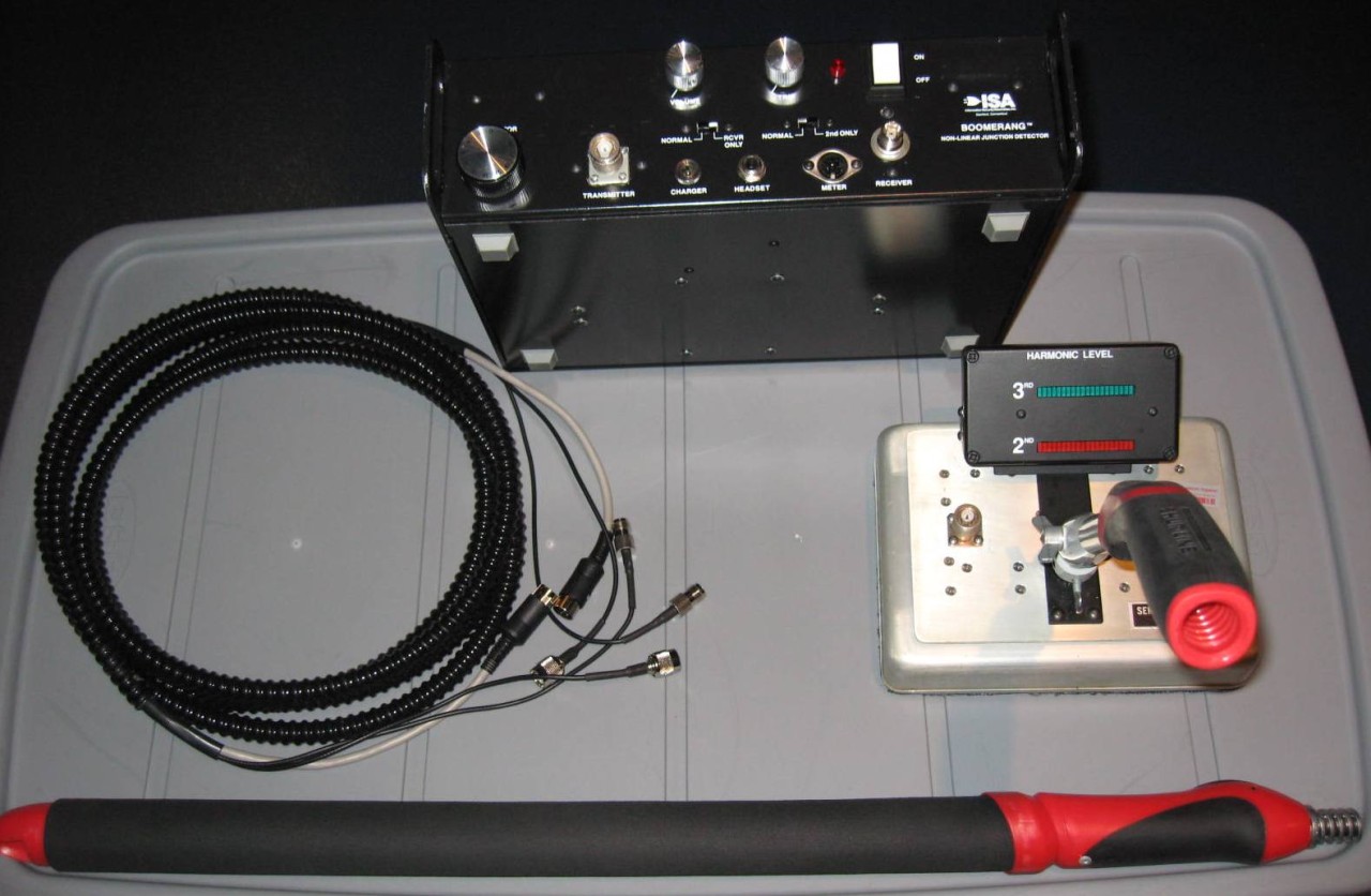
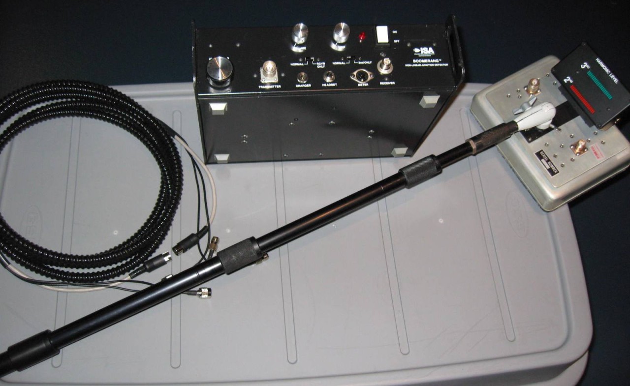
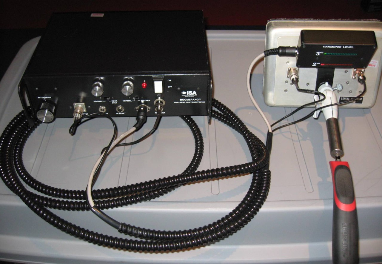
- ISA Boomerang NLJD Model NJD-4 Operator's Manual (400k PDF) (NJD-5)
- ISA Boomerang NLJD Website archive.
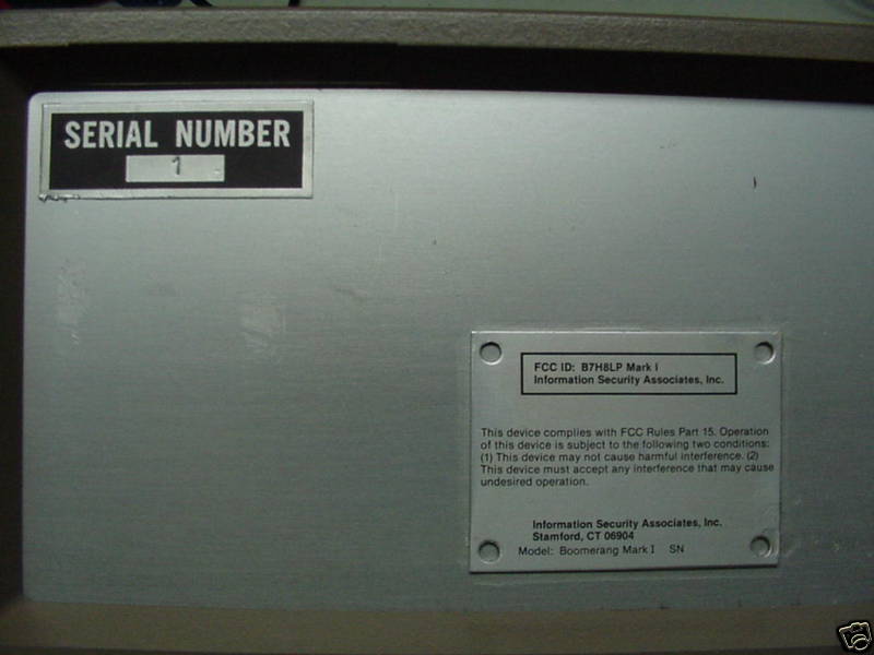
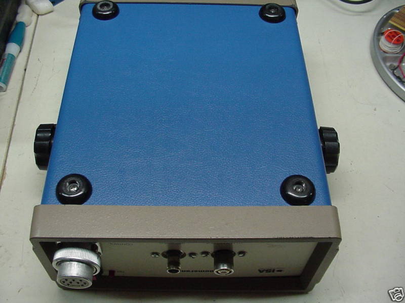
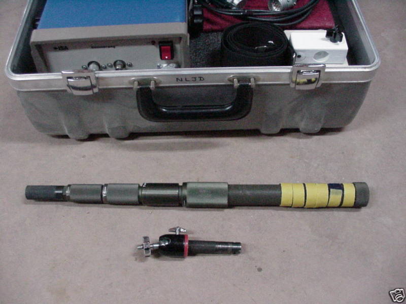
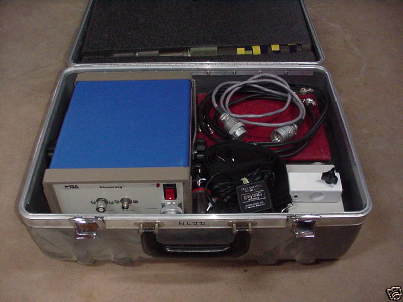
- Picture 1 Boomerang Mark 1, 915 MHz (FCC ID: B7H8LPMARK1)
- Picture 2
- Picture 3
- Picture 4
- Picture 5
- Picture 6
- Picture 7
- Picture 8
- Picture 9
- Picture 10
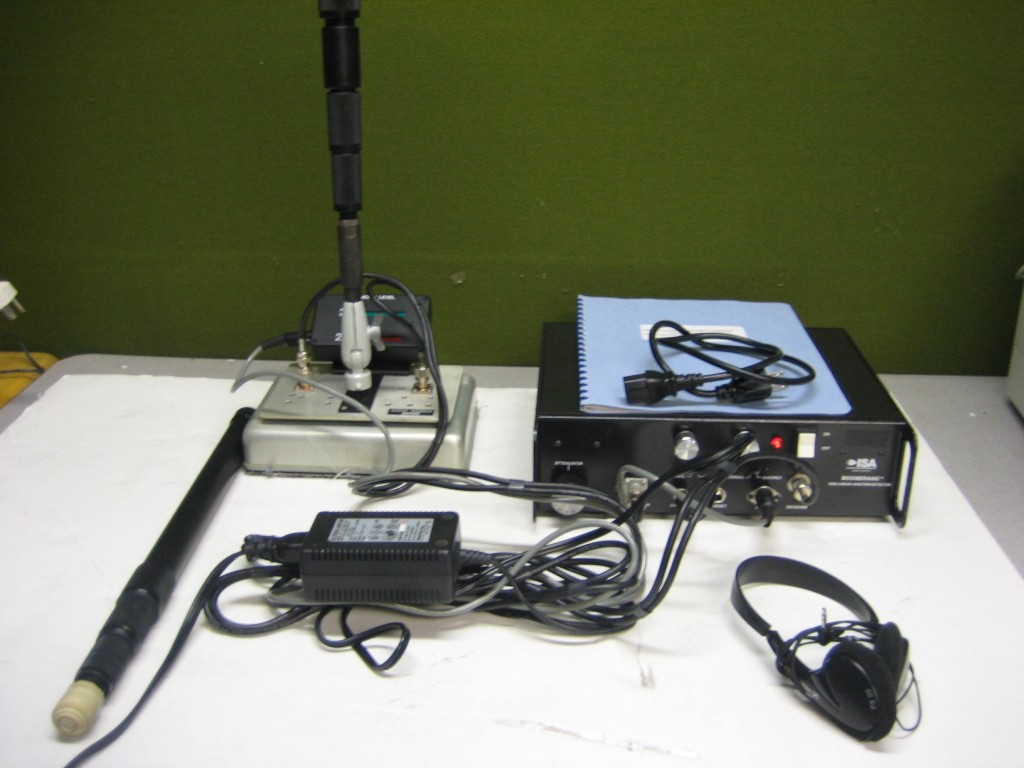
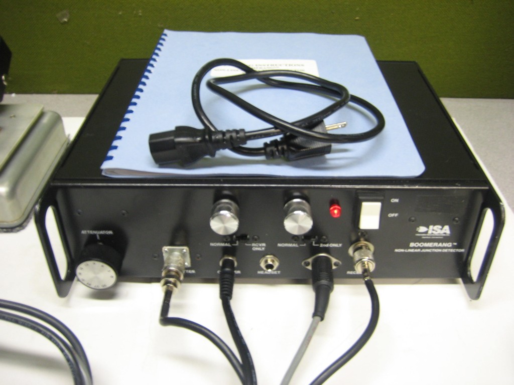
- ISA Boomerang Model NJD-5 Non-Linear Junction Detector 500 mW @ 915 MHz.
- Picture 2
- Picture 3
- Picture 4
- Picture 5
- Picture 6
- Picture 7
- Picture 8
- Picture 9
- Picture 10
- Picture 11
- Picture 12
- Picture 13
- Picture 14
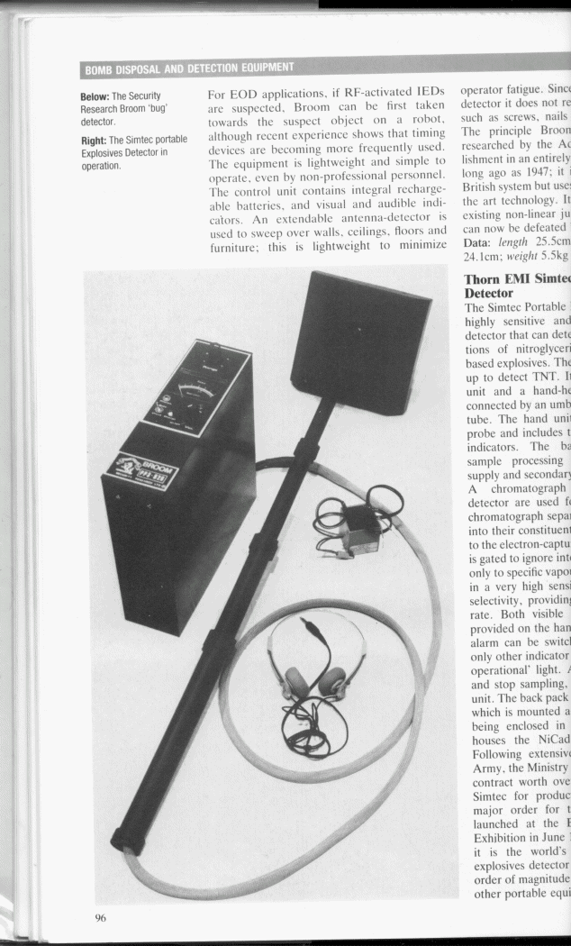
- Security Research Broom Non-Linear Junction Detector
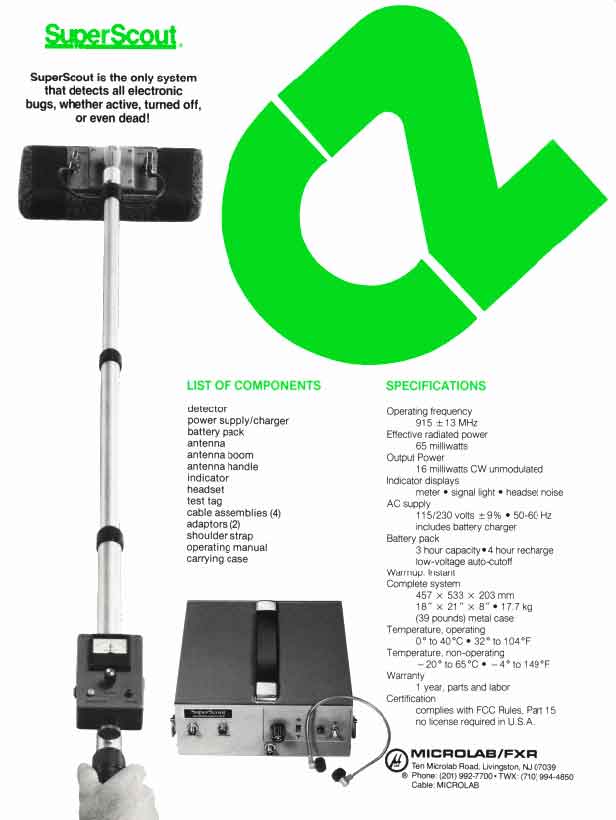
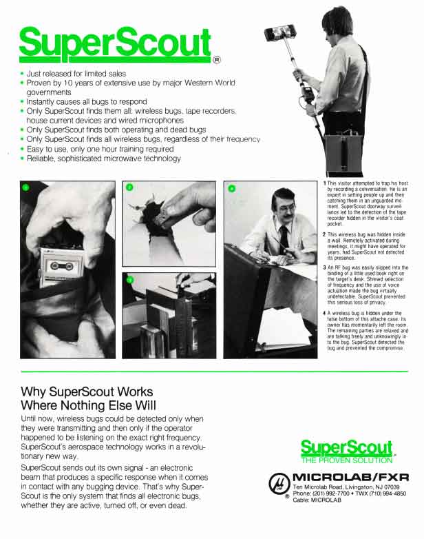
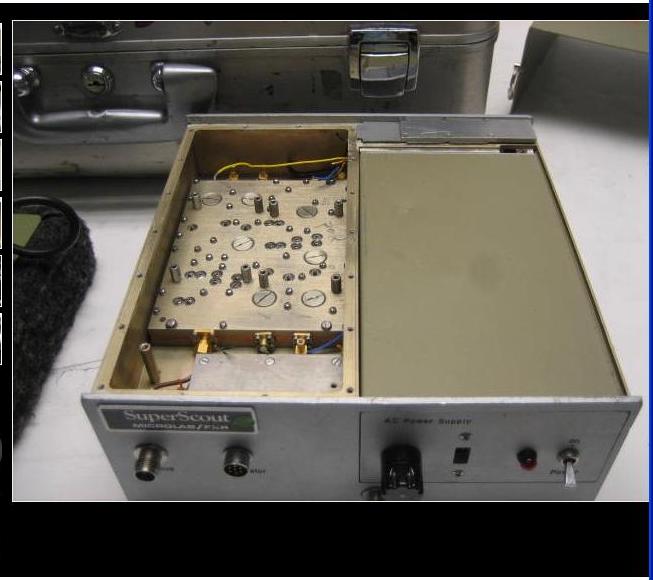
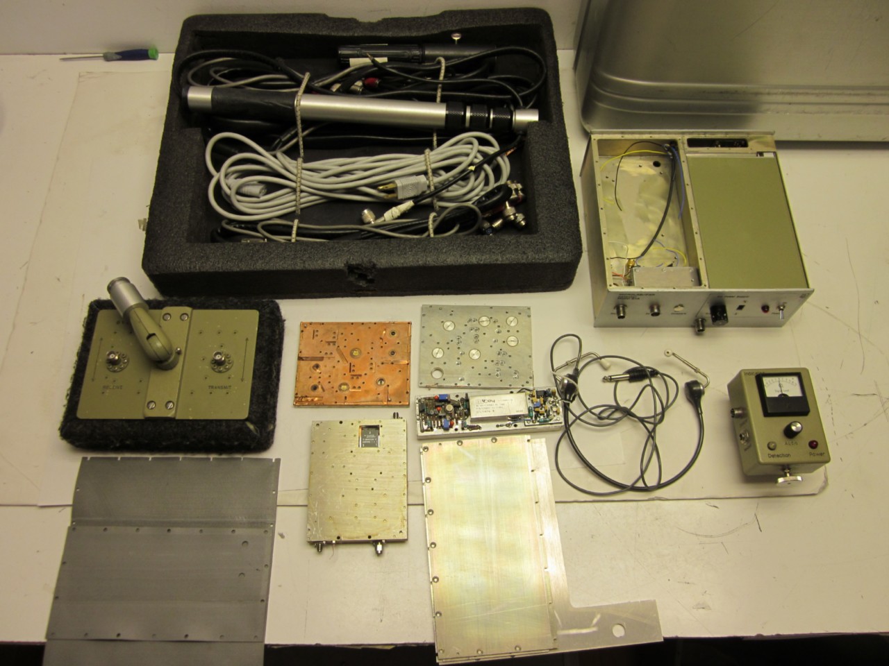
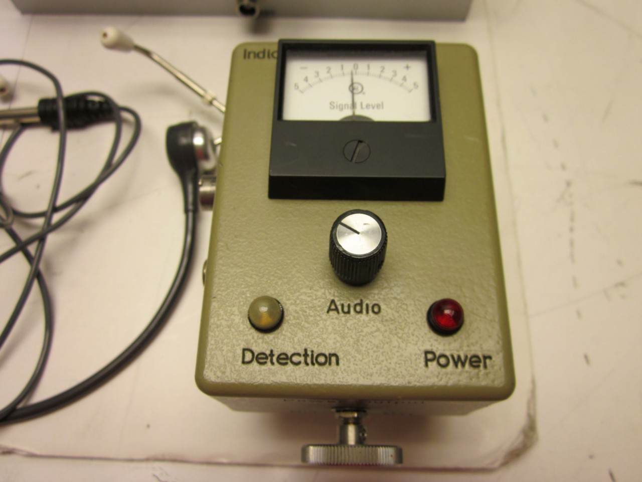
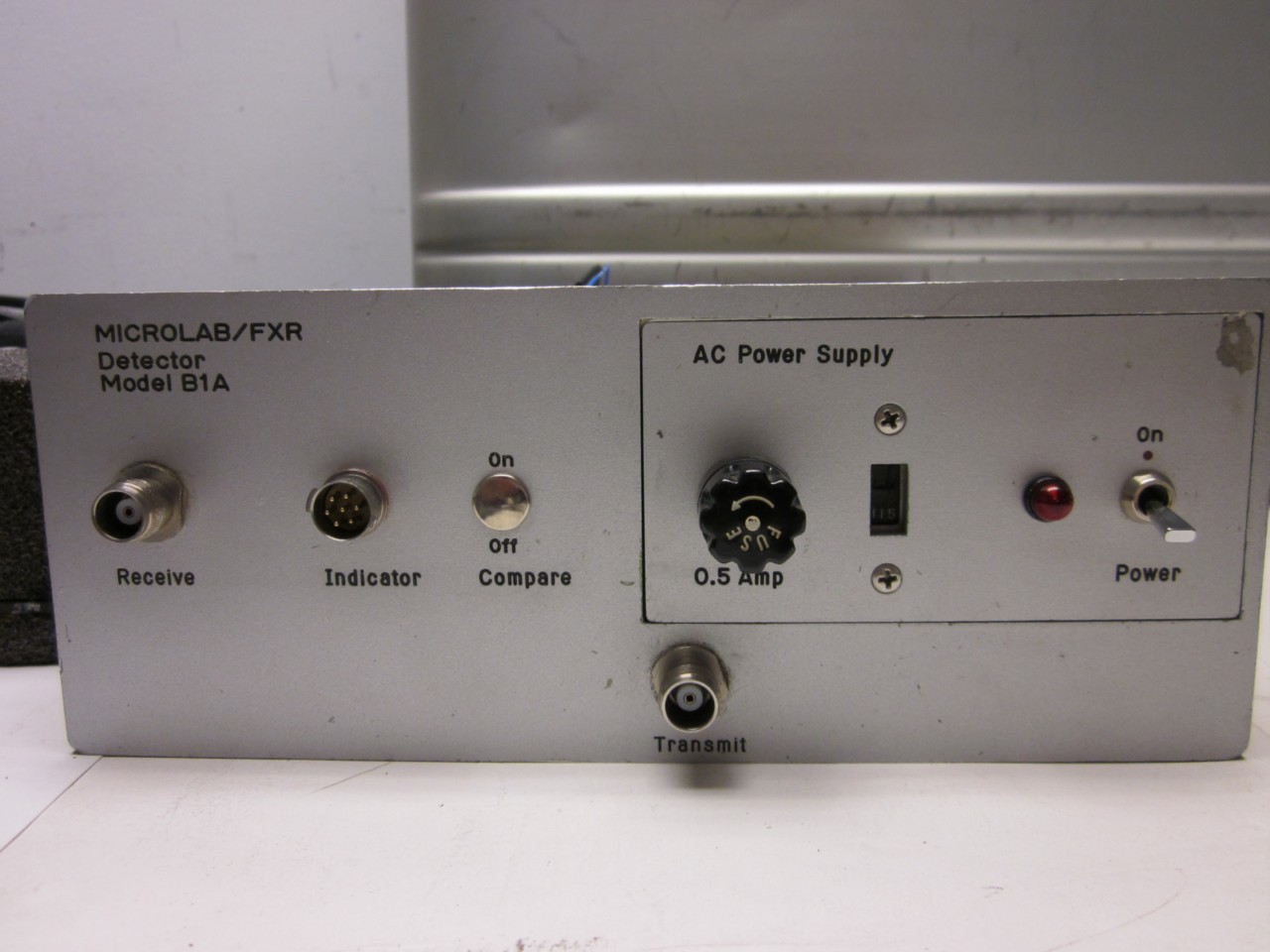
- Microlab/FXR SuperScout Non-Linear Junction Detector (709k PDF) (Flyer - Page 1) (Flyer - Page 2)
- Picture 1
- Picture 2
- Picture 3
- Picture 4
- Picture 5
- Picture 6
- Picture 7
- Picture 8
- Picture 9
- Picture 10
- Picture 11
- Picture 12
- Picture 13
- Picture 14
- Picture 15
- Picture 16
- Picture 17
- Picture 18
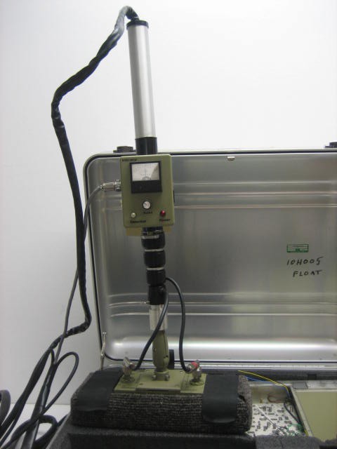
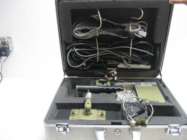
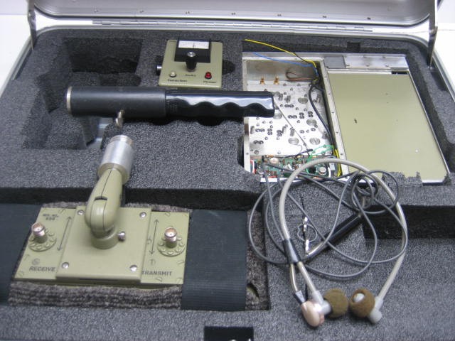
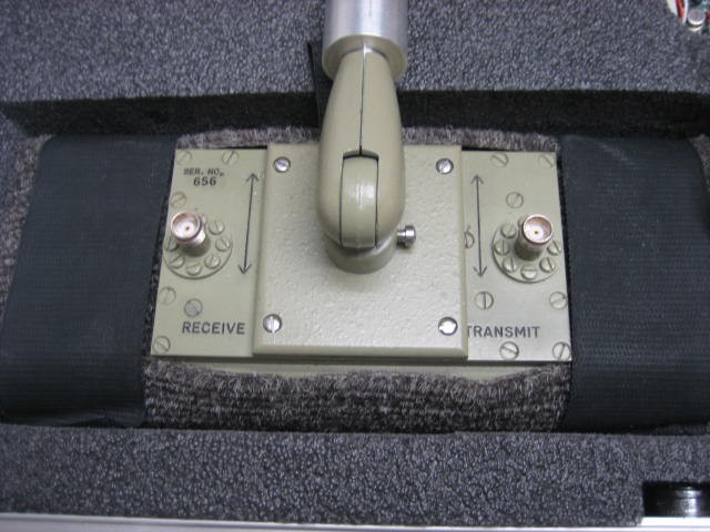
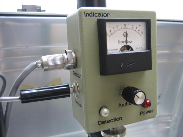
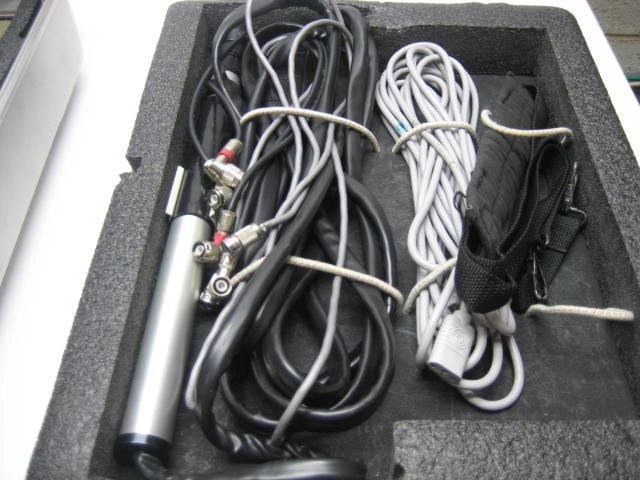
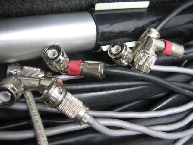
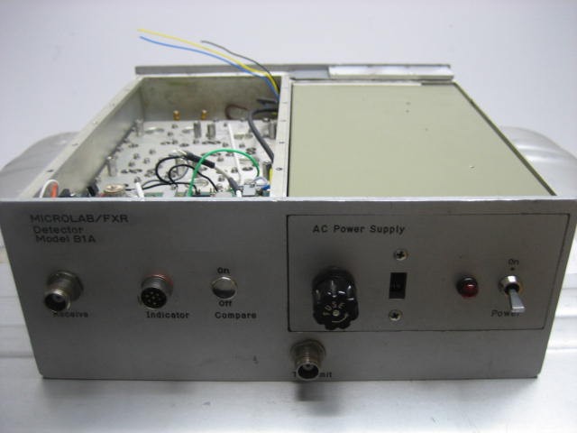
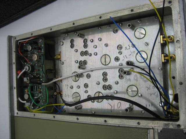
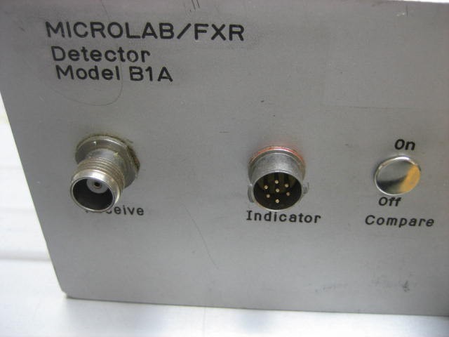
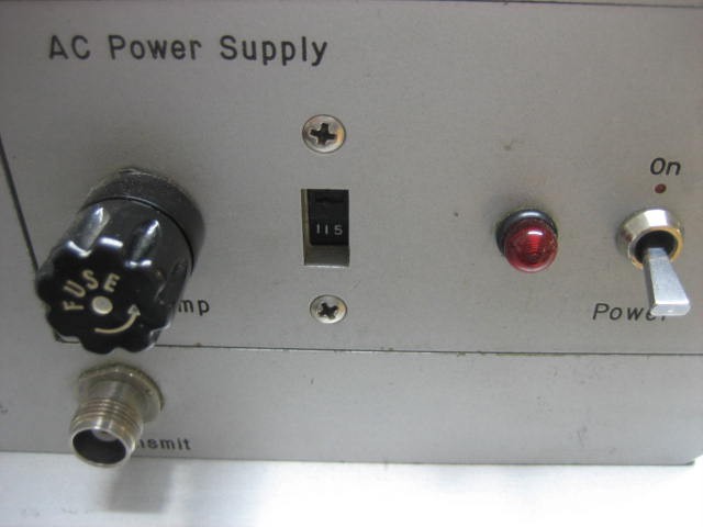
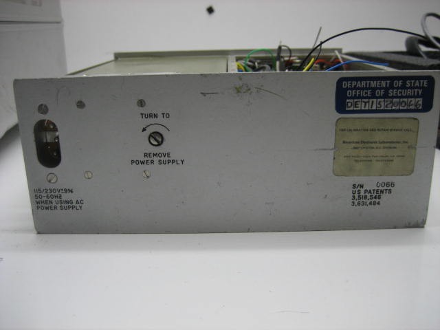
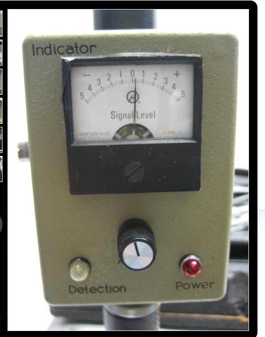
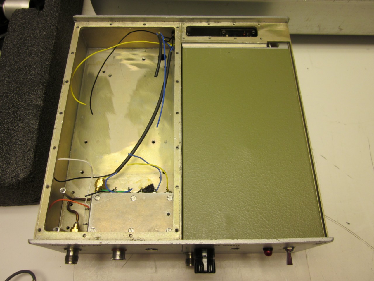
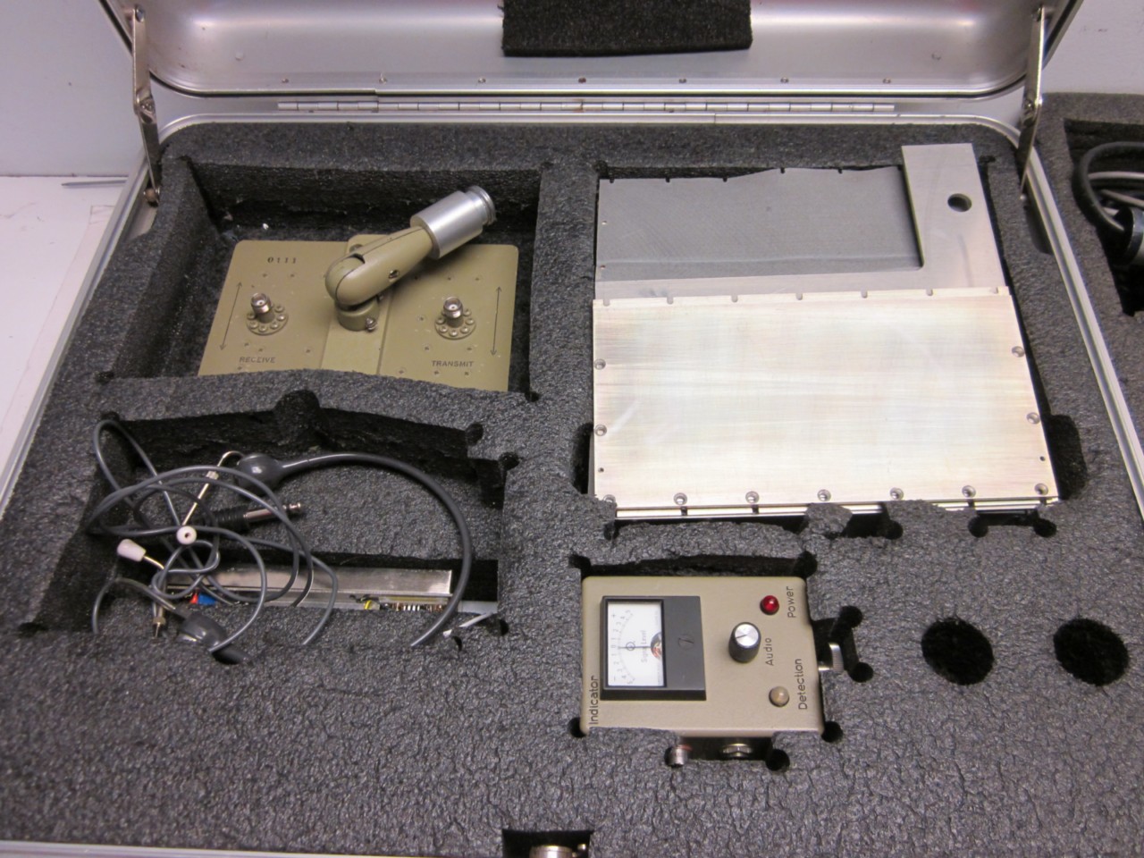
- Microlab/FXR SuperScout Model B1A Non-Linear Junction Detector
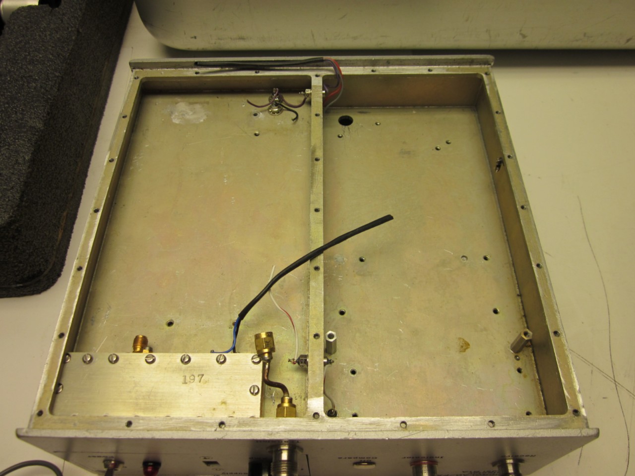
- Picture 2 Internal overview with modules removed.
- Picture 3
- Picture 4
- Picture 5
- Picture 6
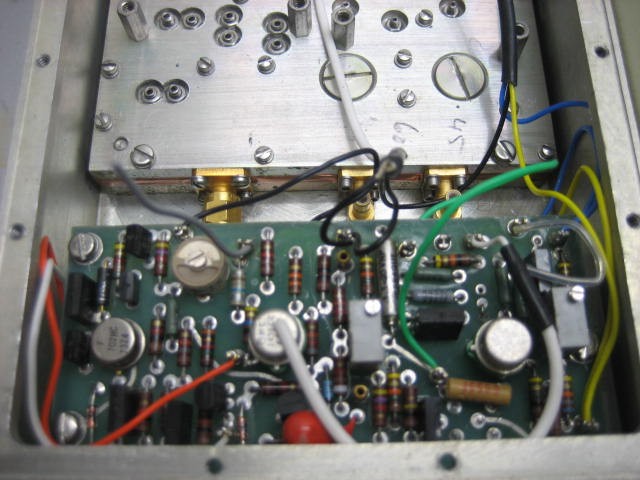
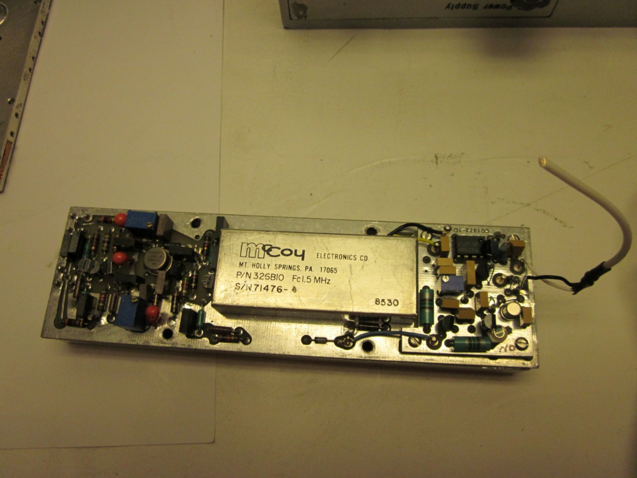
- Picture 7 Closeup of one of the circuit boards. Looks like a 1.5 MHz filter.
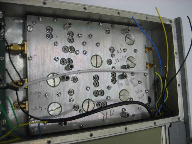
- Picture 8 Group of modules. The 3-port device is a circulator or isolator.
- Picture 9
- Picture 10
- Picture 11
- Picture 12
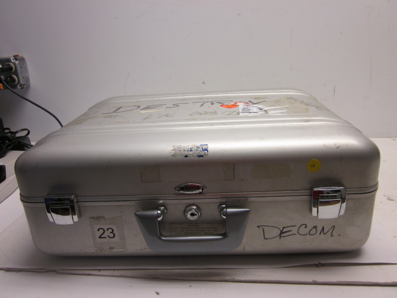
- Picture 13 U.S. government-labeled carrying case.
- History of Non-Linear Junction Detection
- STT Group: Non-Linear Junction Detectors (YouTube Channel)
- Elvira: Non-Linear Junction Detectors Makers of the LORNET-series of NLJDs.
- EDD-24T - Electronic Device Detector by JJN Electronics
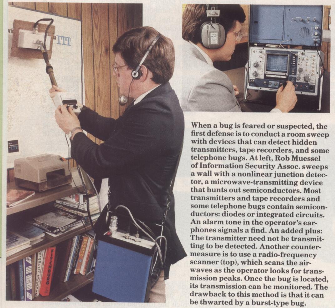
- NLJD in Action!
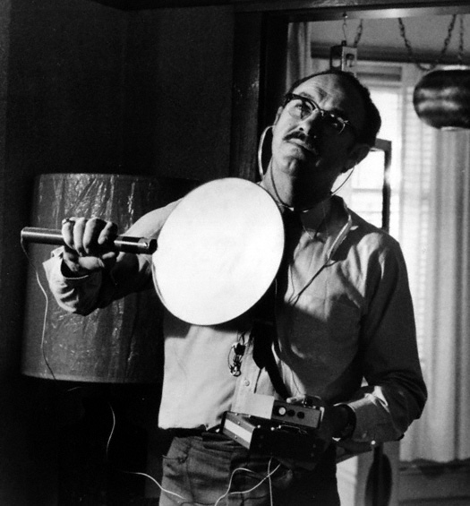
- Screen Capture of Gene Hackman Using a NLJD(?) in The Conversation Or could be some type of VLF loop antenna (tape recorder bias?). Some of the hardware used in that film was actually real.
- Vlad's Bug Detector
- Non-Linear Junction Detector - Note #1
- Non-Linear Junction Detector - Note #2
- Non-Linear Junction Detector - Note #3
- Triple Band Spiral Antenna for Non-Linear Junction Detector
- Harmonic Radar Finds Hidden Electronics Hack a Day
- DIY Non-Linear Junction Detector (NLJD) for Nanotech Detection
Related Videos
Related Patents
- Slot Spiral Antenna with Integrated Balun and Feed U.S. Patent 5,815,122 (543k PDF)
- Non-Linear Junction Detector U.S. Patent 6,057,765 (REI) (1.3M PDF)
- Pulse Transmitting Non-Linear Junction Detector U.S. Patent 6,163,259 (REI) (1.6M PDF)
- Radar Object Detector Using Non-Linearities U.S. Patent 4,053,891 (240k PDF)
- Transponder for Use in Locating Avalanche Victims U.S. Patent 4,331,957 (442k PDF)
- Non-Linear Junction Detector U.S. Patent 6,897,777 (Audiotel) (659k PDF)
- System and Method of Radar Detection of Non-Linear Junctions U.S. Patent 6,765,527 (908k PDF)
- Harmonic Communication and Navigation System U.S. Patent 3,518,546 (555k PDF)
- Harmonic Detection System U.S. Patent 3,631,484 (322k PDF)
Other Related GBPPR Projects
- GBPPR Drone Detection Technology
- GBPPR PHOTOANGLO Experiments
- Passive Resonant Cavity Technical Surveillance Devices
- GBPPR Interferometric Surveillance Device Experiments - Part 1
- GBPPR Interferometric Surveillance Device Experiments - Part 2
- van Eck-style Radiation Interception Experiments
- GBPPR Remote Telephone Surveillance Experiments
- Doppler Stethoscope for E.O.D. Applications
- GBPPR "Havana Syndrome" Experiments
- GBPPR Special Collection Service