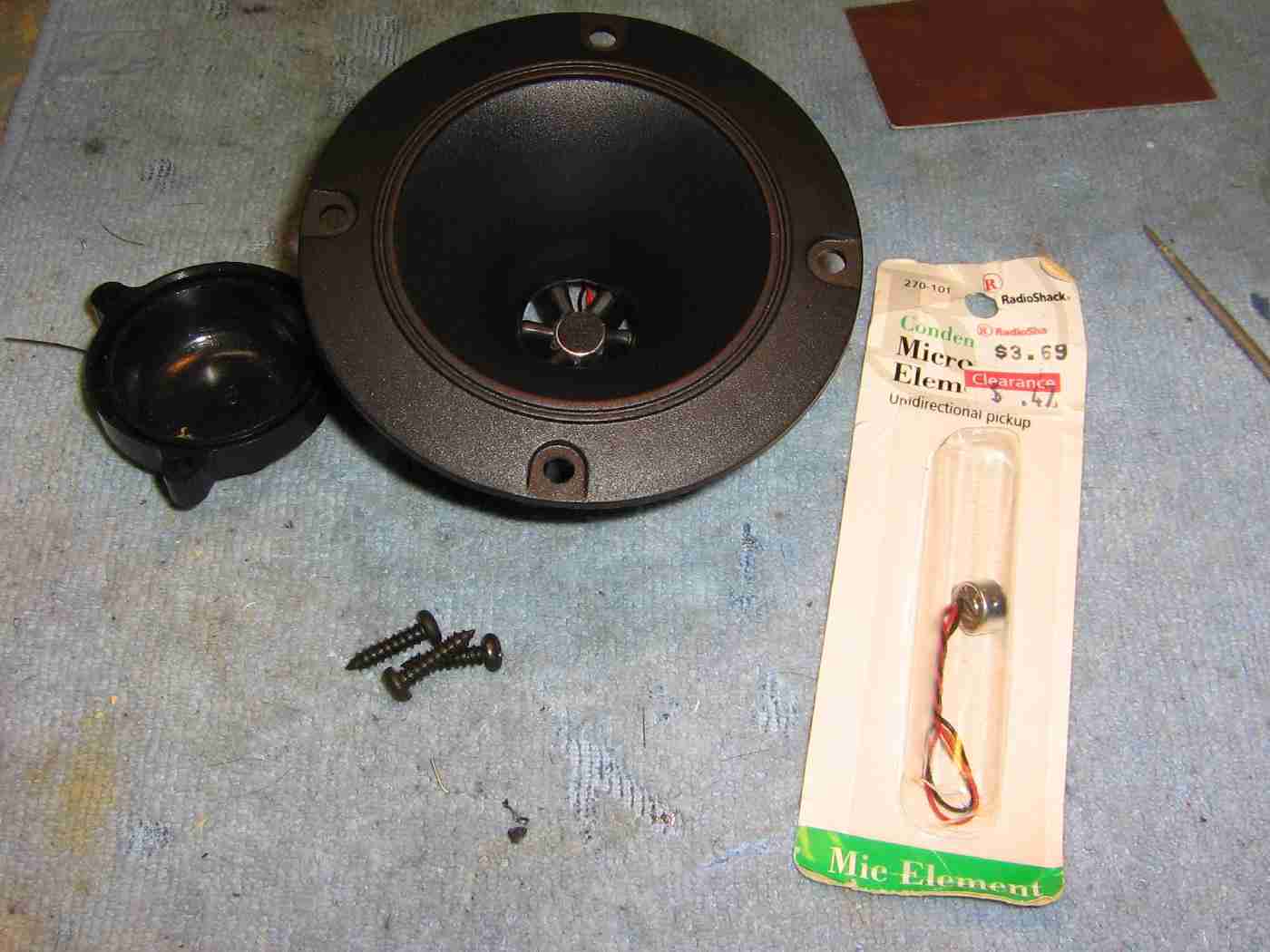
Overview of the 3.5-inch round plastic horn tweeter and electret microphone element which will be mounted inside of it.
You can salvage suitable tweeters from old speakers or purchase similar ones from places like MCM Electronics or All Electronics for a few dollars.
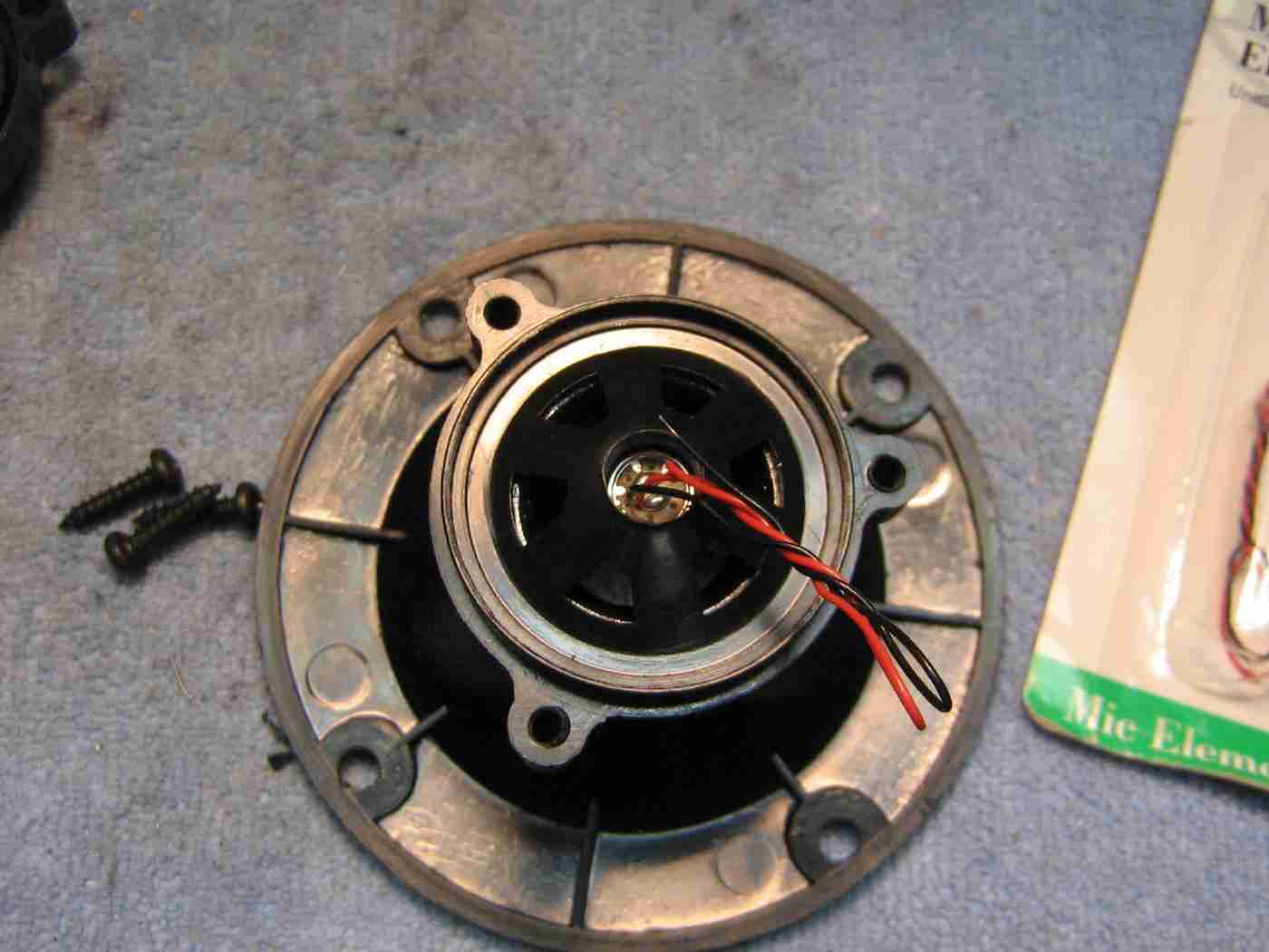
Remove the piezo driver element from the rear of the horn tweeter by removing the three screws and the plastic dome cover.
Drill a hole the same diameter as the electret microphone element into the center plastic sprue of the horn tweeter.
Insert the microphone into this hole and secure it in place with some RTV sealant.
Be sure the connecting wires for the microphone are exposed!
Putting it back together.
You may wish to add a 3/32-inch jack on the rear plastic cover of the horn tweeter for a convenient connection to the microphone element. This is optional, but handy.
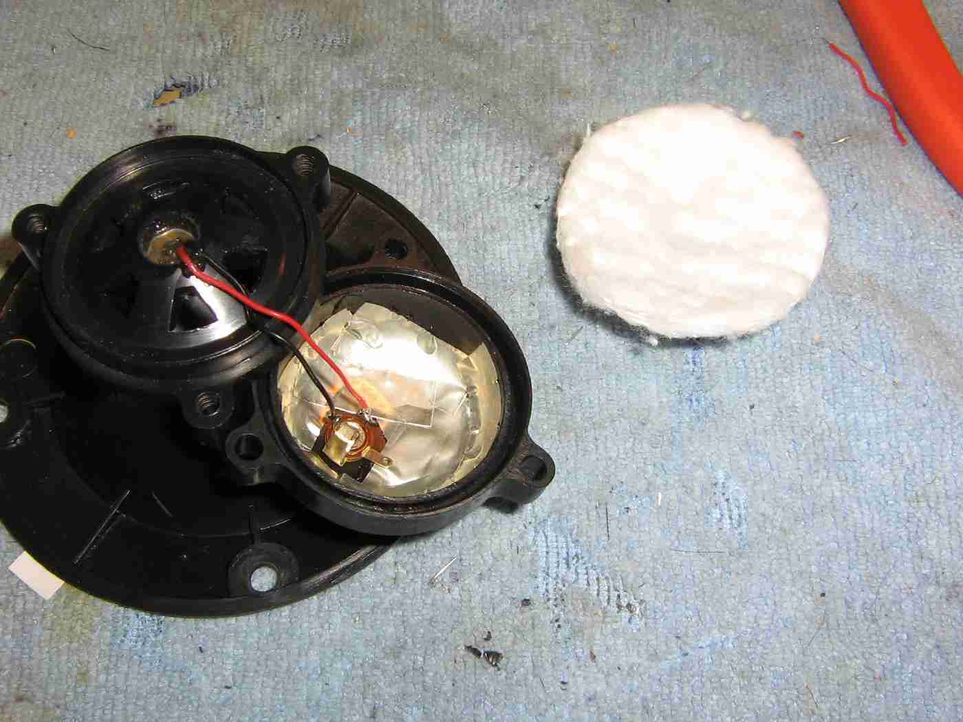
A few strips of metallic tape were added inside the rear cover to help shield it a bit from RF interference.
A couple of roughed-up cotton makeup remover pads were slipped inside the rear cover to dampen any incoming audio which may be off-axis from the microphone's pickup.
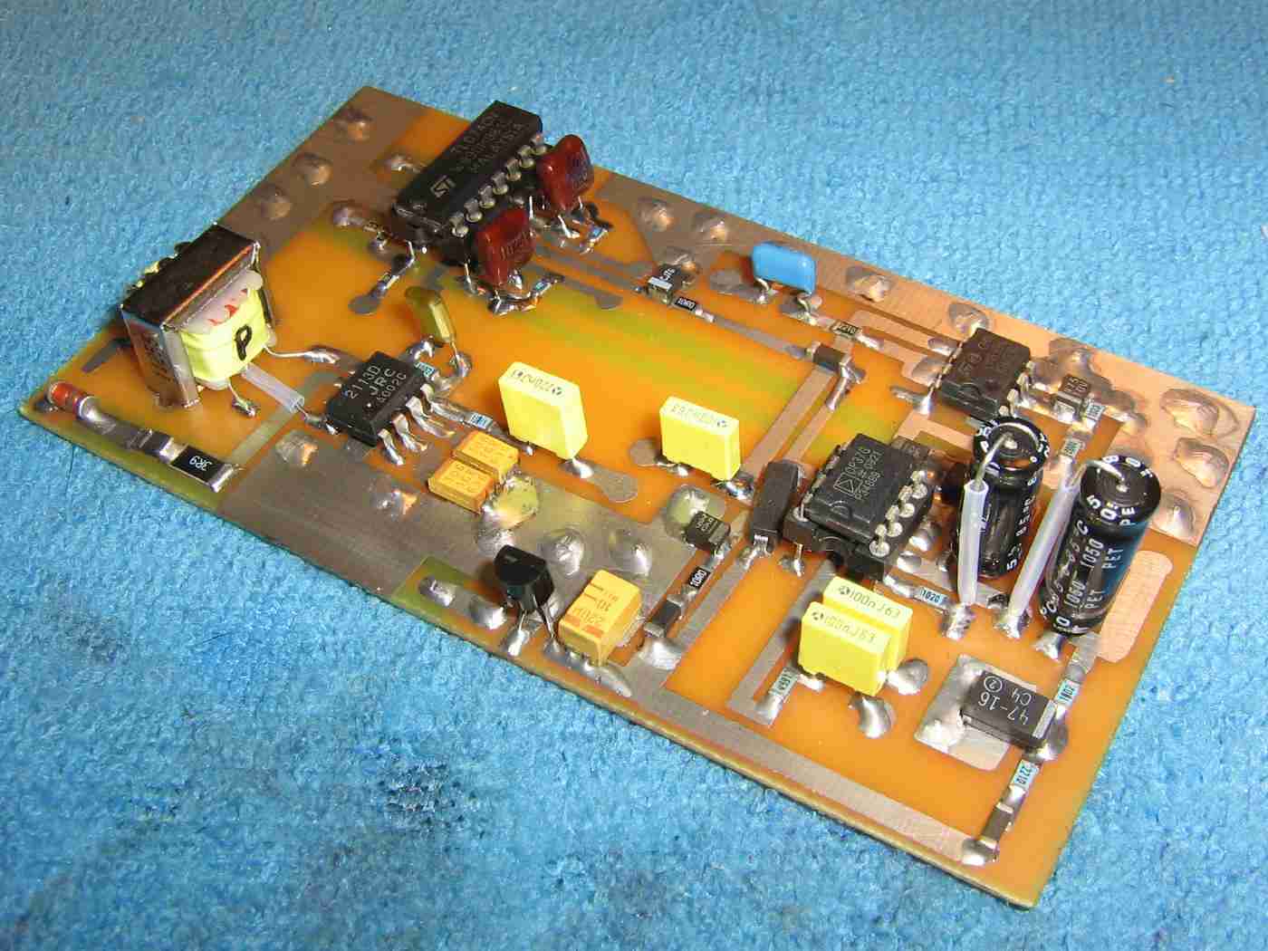
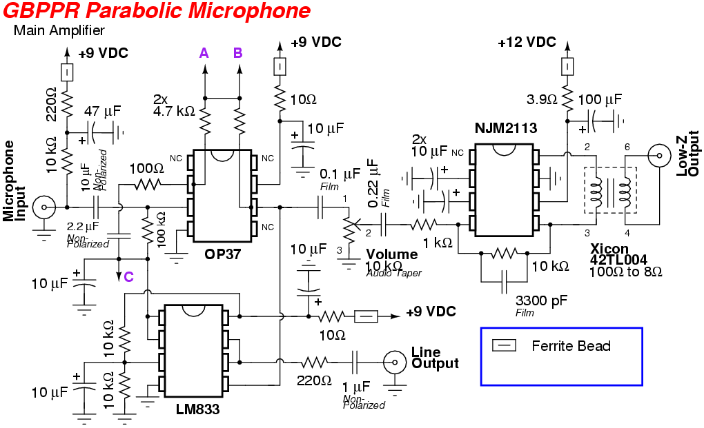
Overview of the GBPPR Parabolic Microphone amplifier circuit.
It's a standard low-noise op-amp design, but with two tunable frequency gain stages in the op-amp's feedback network.
The audio gain is around 40 dB when not in "boost" mode, and can reach the open-loop gain of the op-amp for a particular frequency when tuned for maximum boost. This can be over 80 dB in some op-amps.
A NJM2113 low-noise audio power amplifier provides another 20 dB of gain and can drive a pair of standard headphones or a speaker.
An optional Line Output is available for connecting the amplified audio output to other devices, such as a recorder or soundcard.
A 78L09 voltage regulator provides a clean source of +9 VDC for the op-amps and microphone bias.
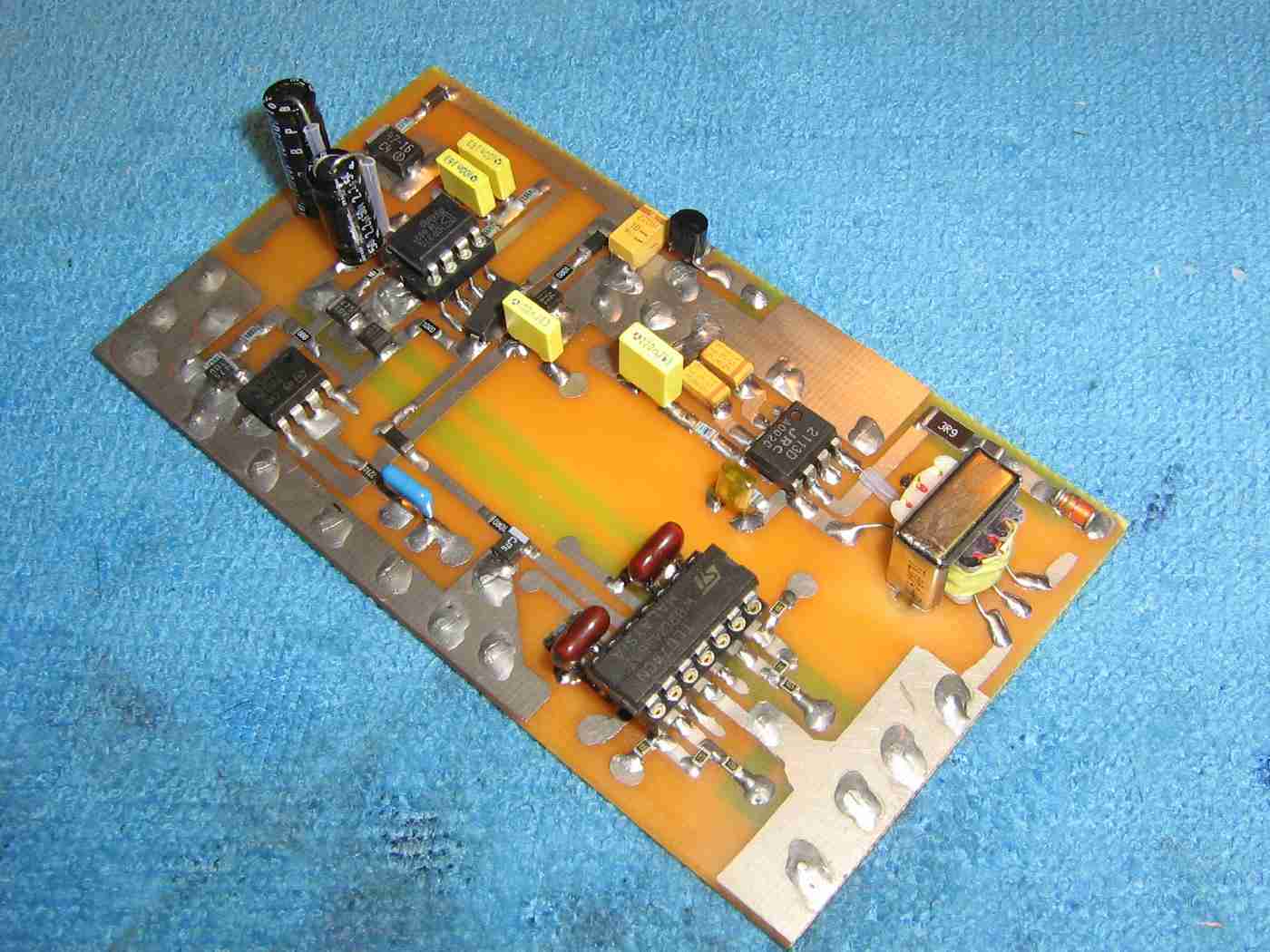
Alternate view.
The JRC NJM2113 low-noise audio power amplifier and Xicon/Mouser 42TL004 isolation transformer are on the lower-right.
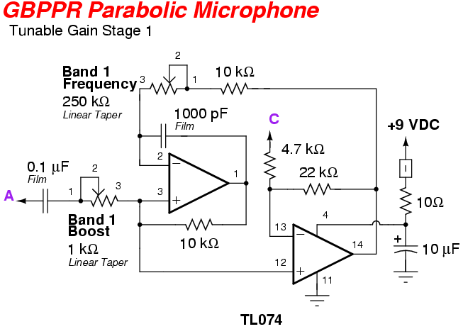
The TL074 quad op-amp for the tunable frequency gain stages is on the lower-left.
Panel-mounted 1k ohm and 250k ohm potentiometers determine the boost level and frequency of the tunable gain stage.
The tunable frequency range is from around 700 - 3,500 Hz. Because parabolic microphones tend to be swamped with low-frequency noise, it's ideal for a bit of high-pass filtering to take place in each of the gain stages.
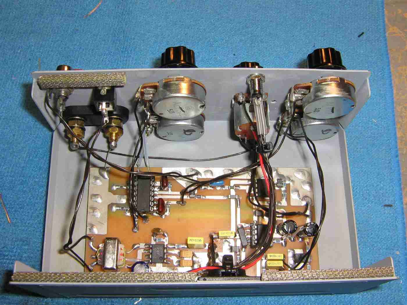
Mounting the circuit board inside an old printer switch case.
The banana jacks on the upper-left are for the +12 VDC power input.
The Lo-Z Output (headphone) and Line Output jacks are above the banana jacks.
The Band 1 Boost and Band 2 Boost 1k ohm potentiometers are on the upper-left.
The 10k ohm Volume/Power potentiometer is mounted in the middle. It has an integrated on/off switch for circuit power.
The Band 1 Frequency and Band 2 Frequency 250k ohm potentiometers are on the upper-left.
A 1/8-inch jack for the microphone input is underneath the Volume potentiometer.
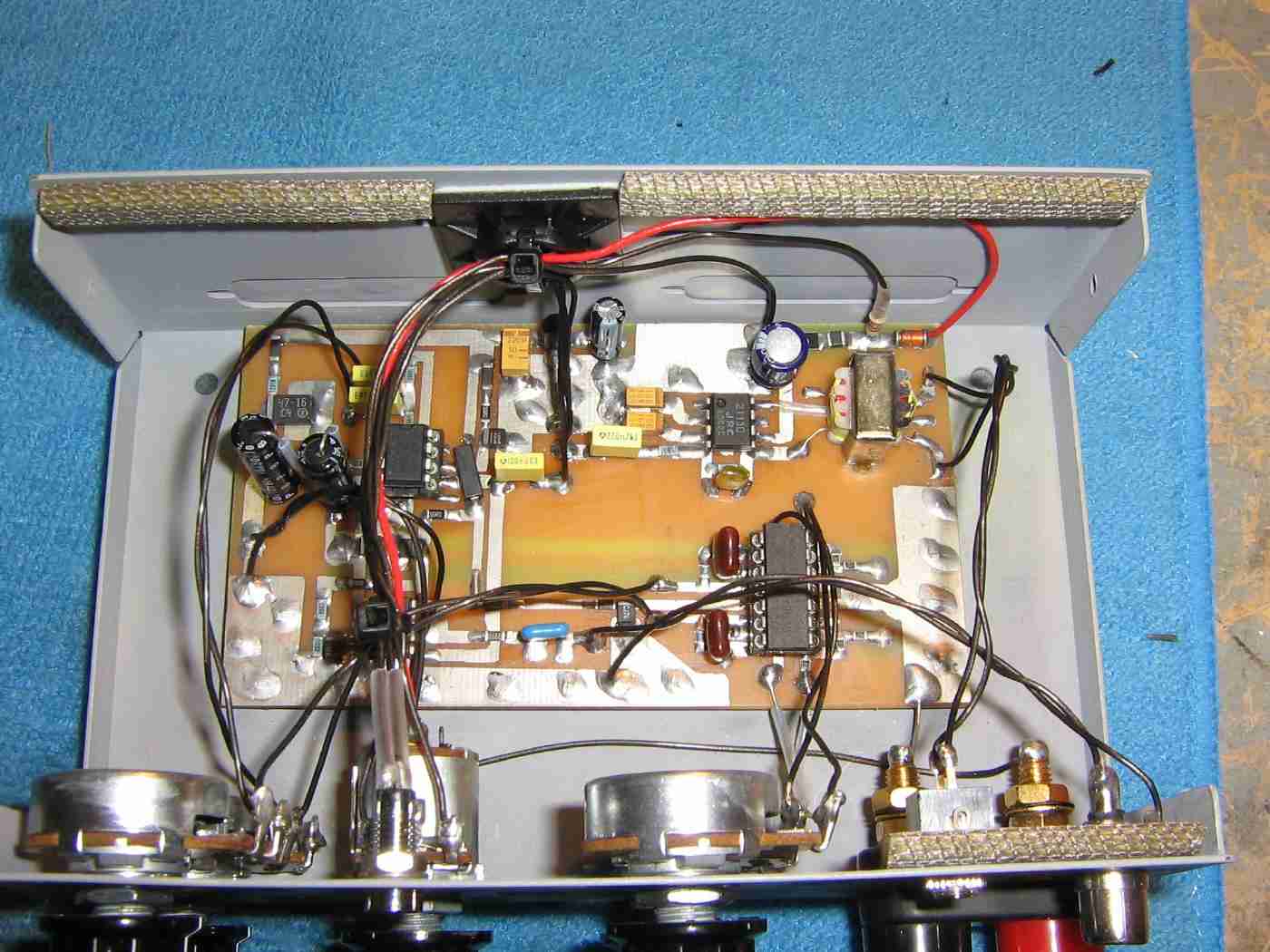
Alternate interior view.
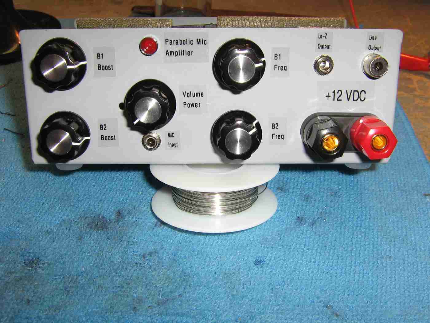
Completed front-panel overview.
Standard 1/8-inch jacks are used for the MIC Input and Lo-Z Output.
A RCA jack is used for the Line Output.
There is a red power-indicating LED above the Volume/Power control.
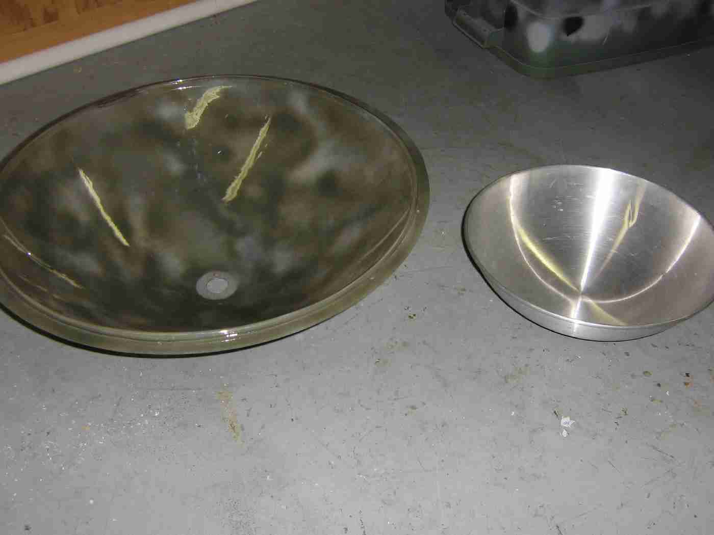
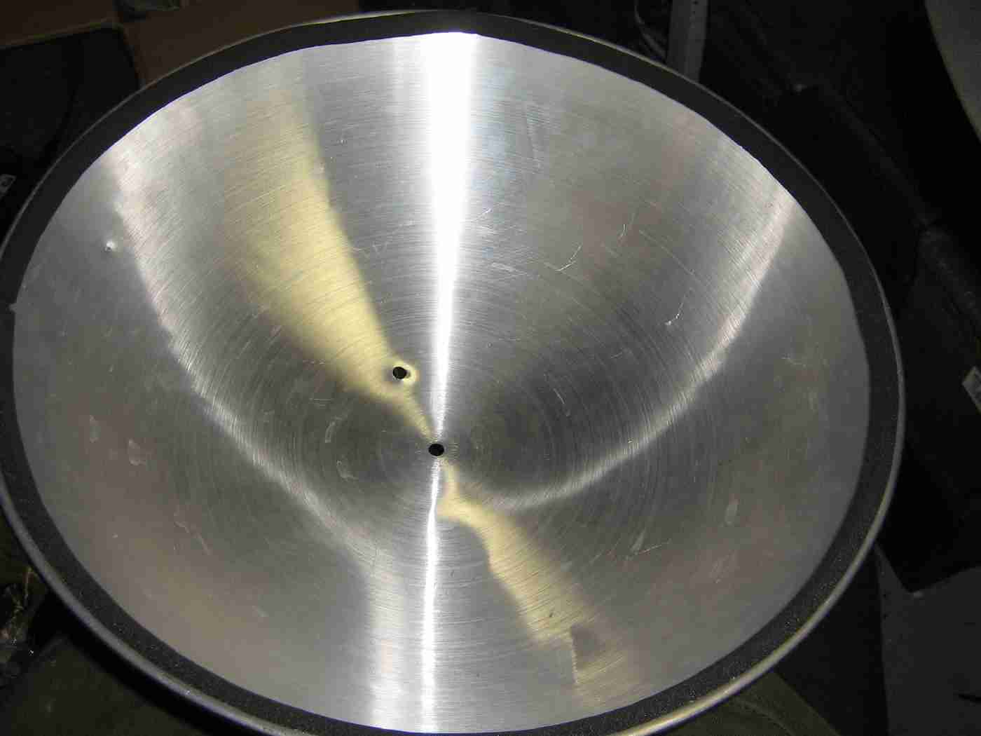
Overview of the main plastic parabolic reflector and an aluminum wok lid which will be used for mounting the parabolic reflector.
For a source of the plastic parabolic reflectors, search for "Parabolic Project Reflector Dish Microphone Science Output Nature Recording" on eBay. The user selling them is "sdill471."
A few coats of camouflage spray paint should be added to the parabolic reflector to help knock down its glare.
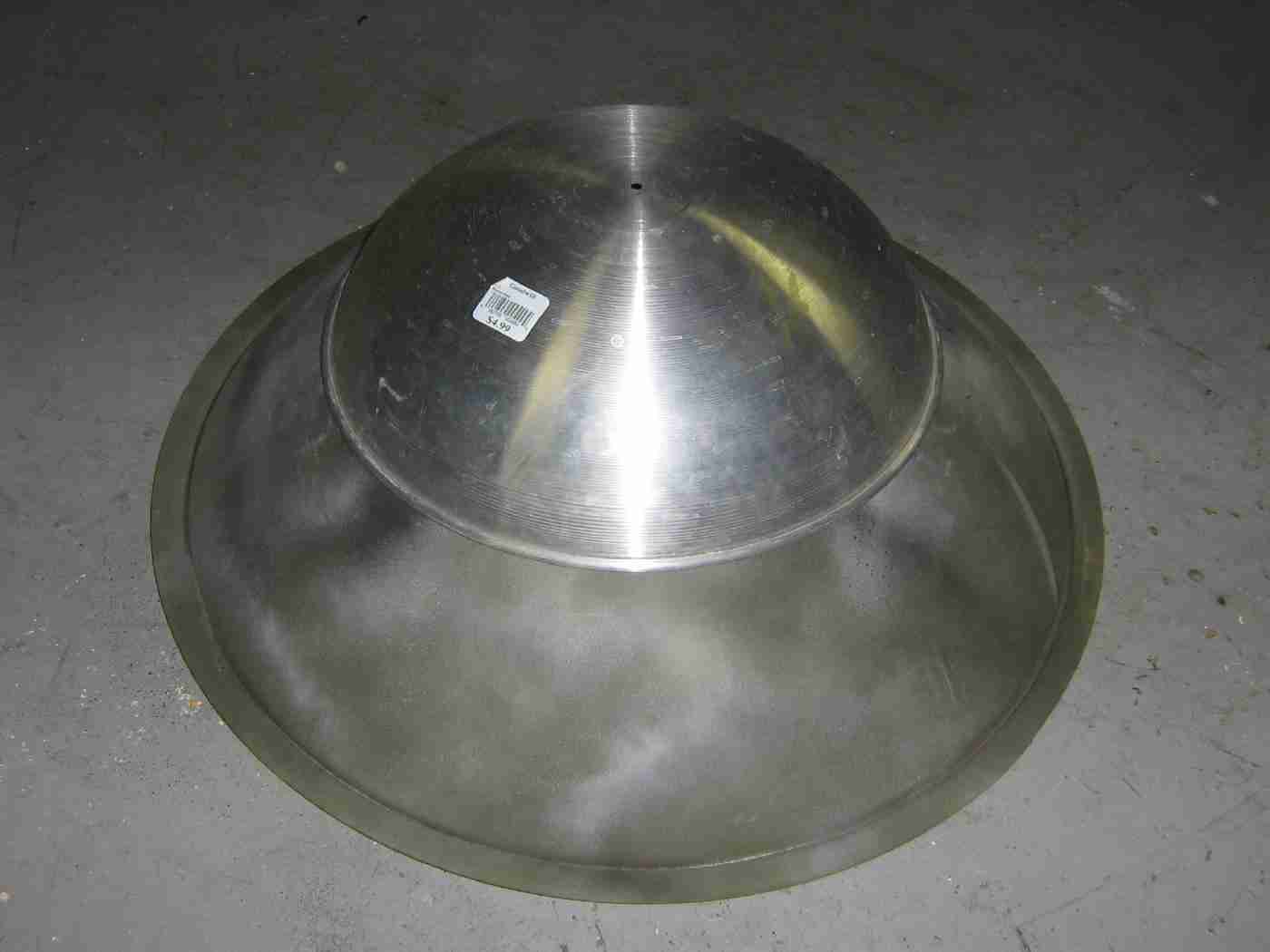
The aluminum wok lid will be mounted behind the plastic parabolic reflector to act as a mounting point and to prevent the parabolic reflector from flexing.
It's a bit of a hack, but it seemed to work out quite well.
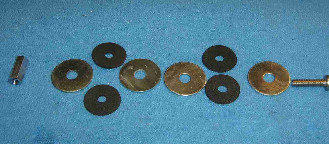
Overview of the parabolic reflector mounting hardware.
Standard 1/4-20 hardware with fender washers.
Some optional rubber washers can be mounted between the fender washer for vibration damping.
A 1/4-20 coupling nut will protrude from the real of the parabolic dish to act as the final mounting point.
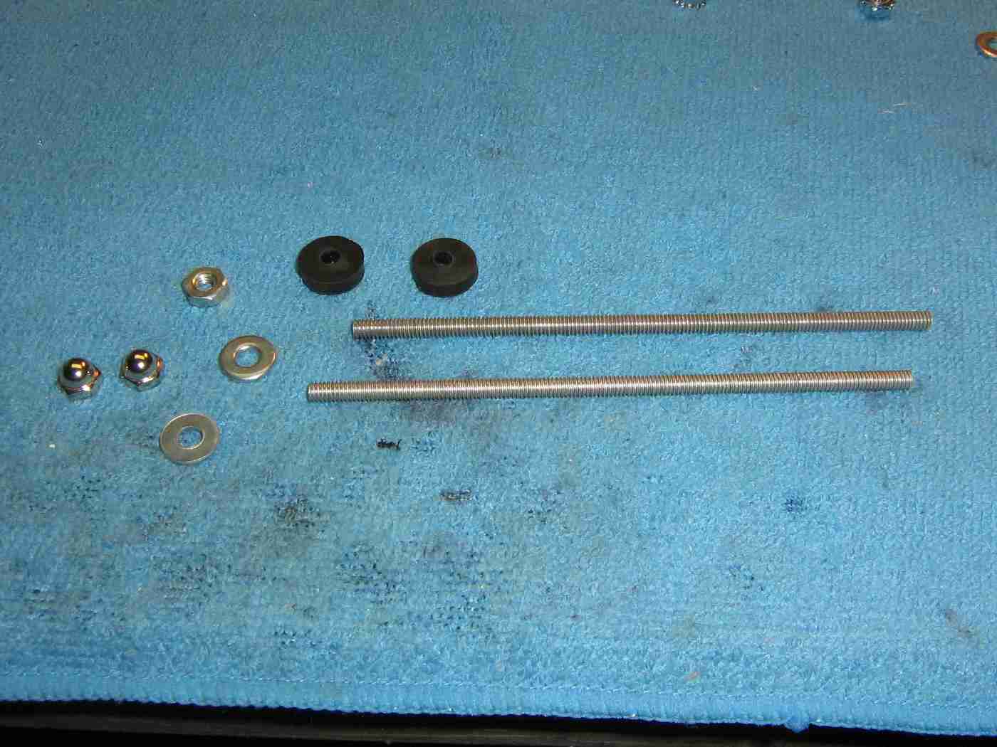
Overview of the mounting hardware for the horn tweeter.
Standard #8-32 hardware will be used along with some rubber plumbing washers for vibration damping.
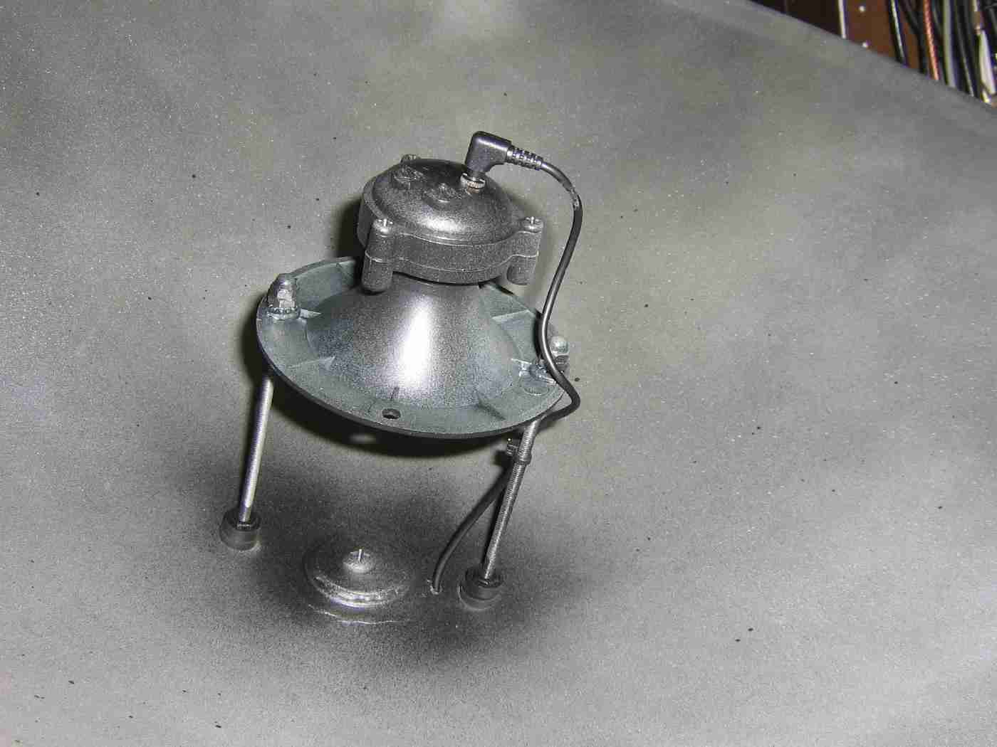
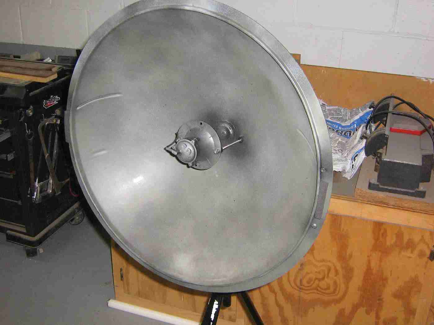
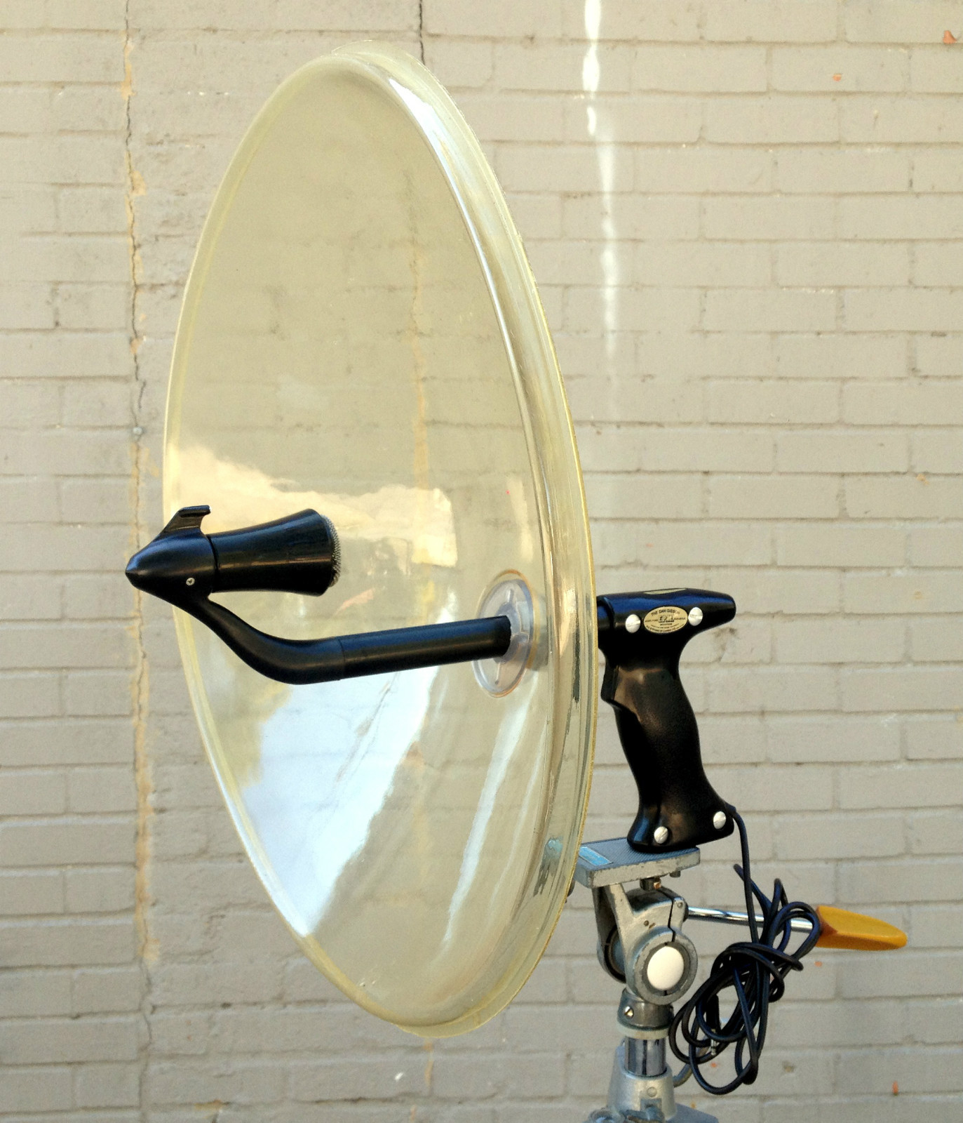
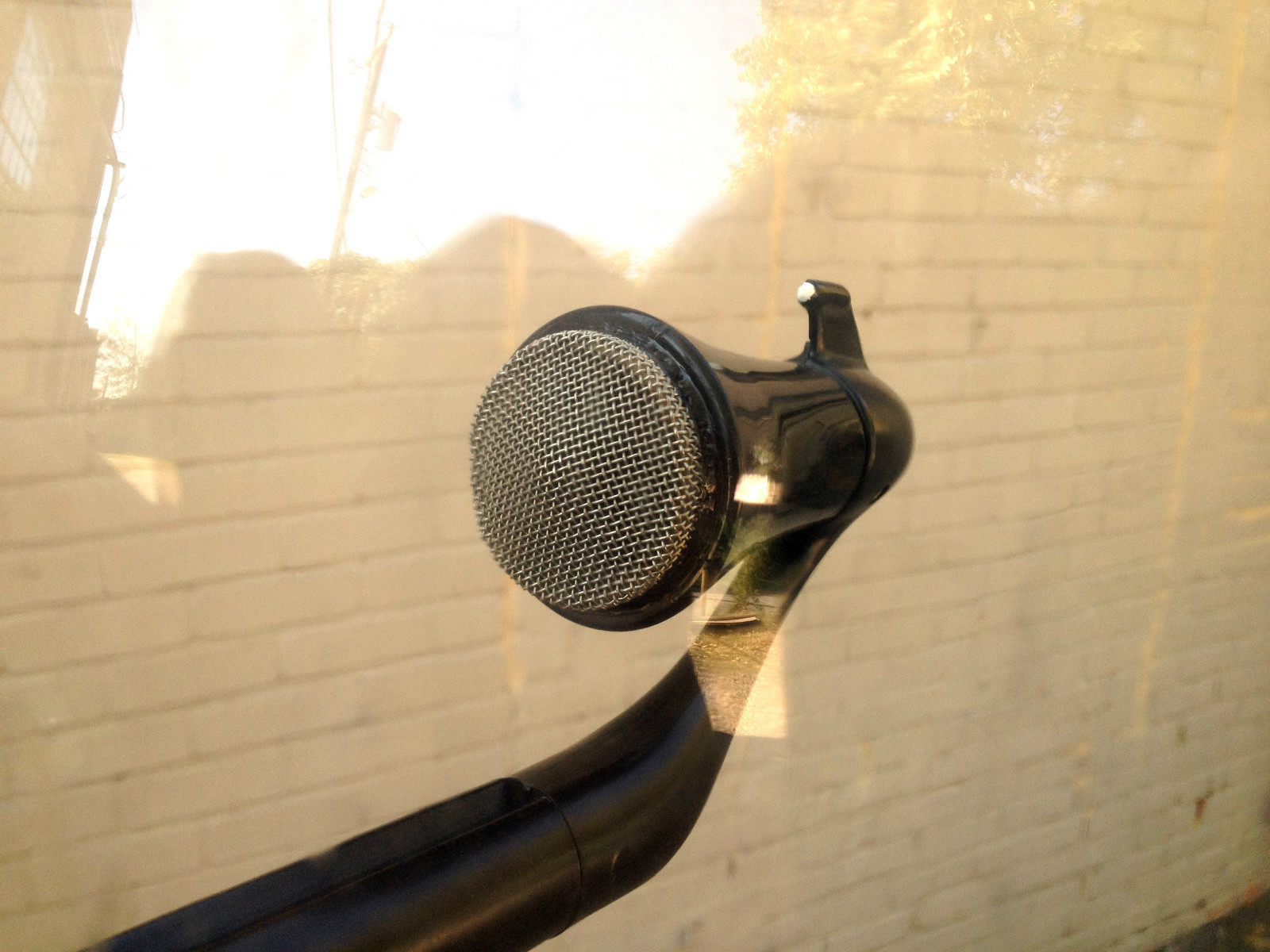
Mounting the horn tweeter at the focal point of the dish.
It's 3.75-inches from the bottom of the dish to the lip of the horn tweeter. This places the focal point just inside the horn tweeter.
You may wish to experiment with the focal point positioning for maximum audio performance.
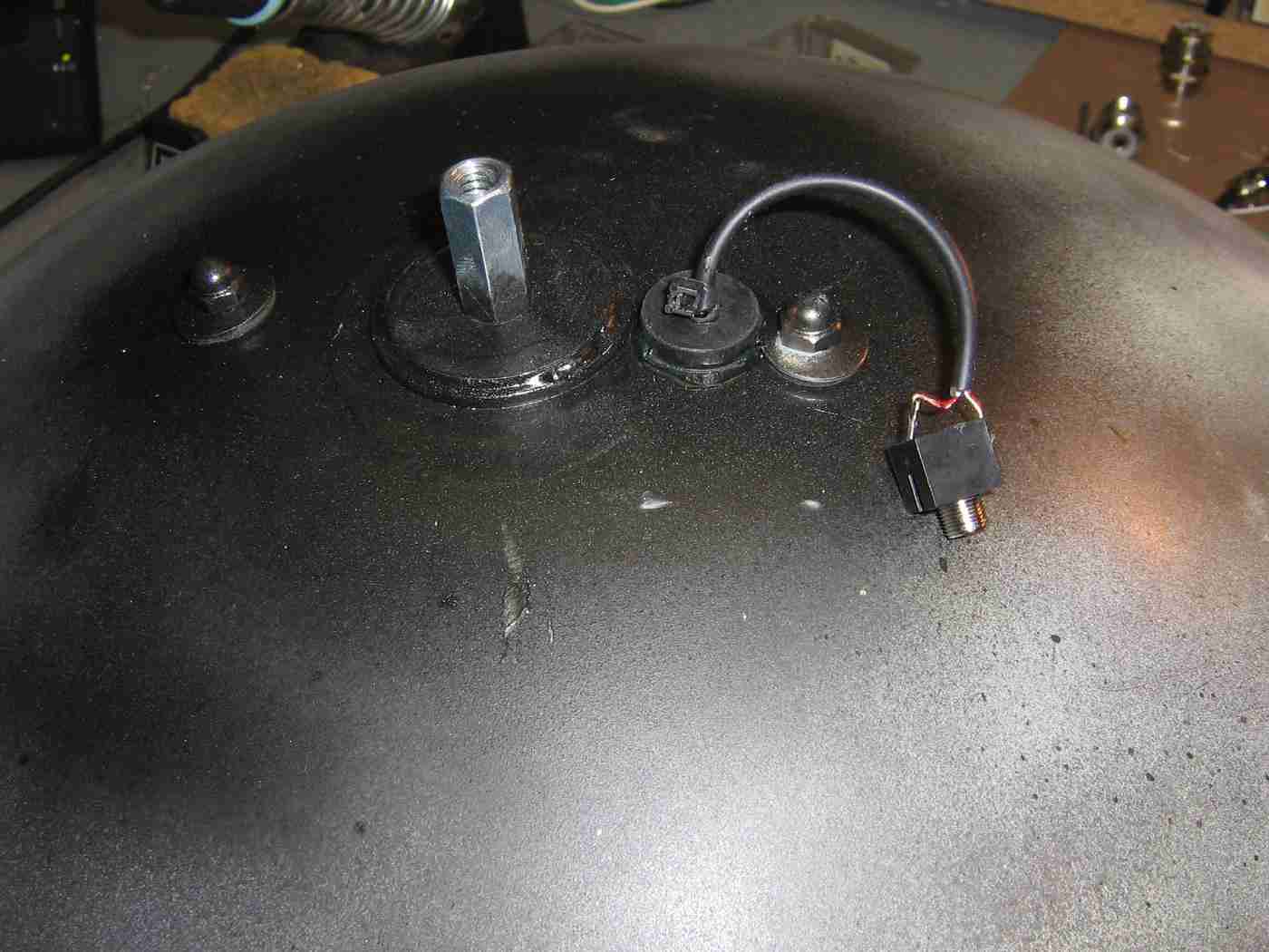
Rear view of the parabolic dish after all the mounting hardware has been added.
You should remember to drill a hole to pass the connection wires for the microphone element.
Drill a 1/4-inch hole in the bottom of the wok lid for attachment to the coupling nut coming out the back of the parabolic reflector.
You should also drill a hole for a panel-mount 3/32-inch or 1/8-inch jack for the microphone connection.
Some window insulation foam tape was added to the rim of the wok lid to aid in vibration damping.
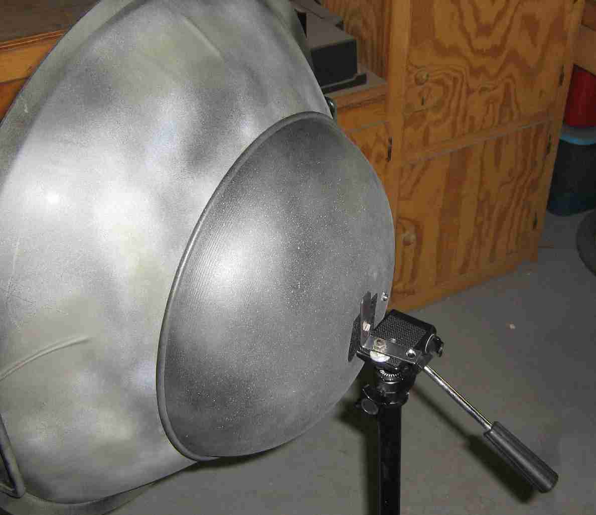
The wok lid is attached to the parabolic reflector using a 1/4-20 bolt and a L-bracket.
The L-bracket allows the parabolic dish to then be attached to a standard camera tripod.
You may want to improve this mounting design a little bit. The key is to reduce any source of vibration in order to eliminate the low-frequency "rumble" which will override the target audio signal.
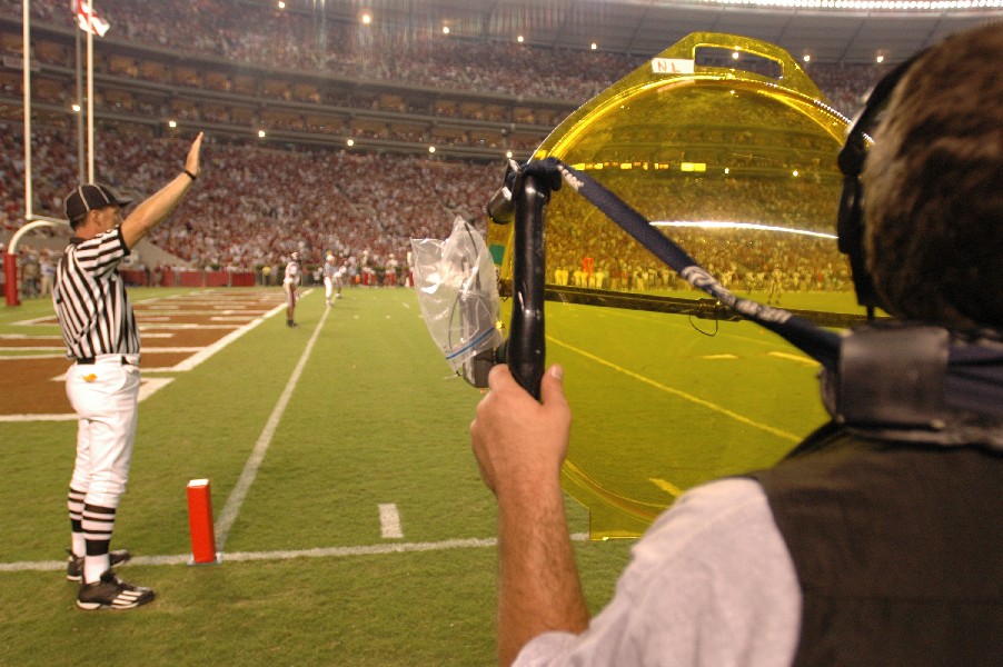
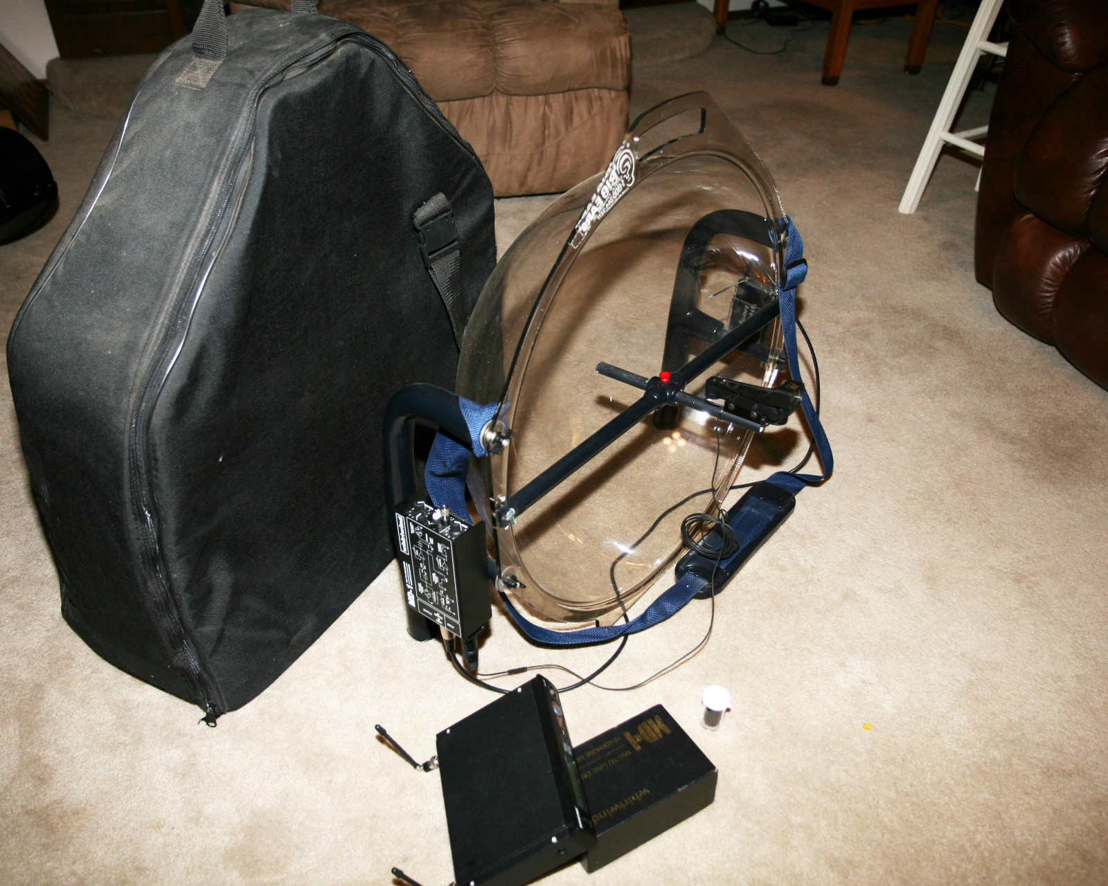
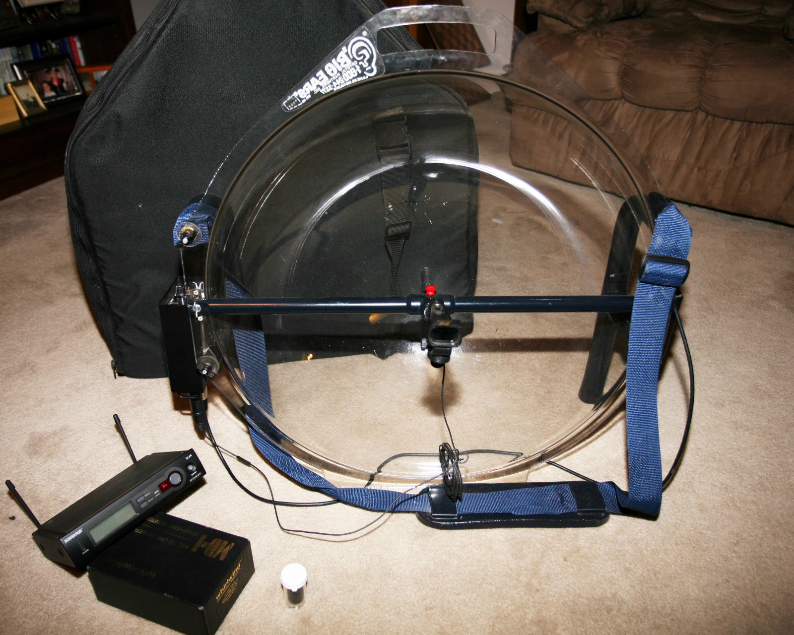
Overview of the completed GBPPR Parabolic Microphone.
To operate the amplifier, apply the DC power and set the Volume control to a usable setting.
Turn both the Band 1 Boost and Band 2 Boost controls to their minimum boost level (counter-clockwise).
Point the dish in the direction of the target audio and tune the Band 1 Frequency and Band 2 Frequency controls into the frequency range of the target audio.
Slowing increase the Band 1 Boost and Band 2 Boost controls to help bring out those particular frequencies. Retune the Band 1 Frequency and Band 2 Frequency controls, if necessary.