Start with about sixty feet of 1/2-inch O.D. aluminium tubing. The original article used 3/8-inch diameter tubing, but 1/2-inch seems to be much easier to find at the hardware store. Also pick up some two-part, fast-drying epoxy, and a good tubing cutter. Copper tubing can be used in a pinch.
Start cutting the tubing per the Popular Electronics article. Cut one 36-inch piece, one 35-inch piece, one 34-inch piece, one 33-inch piece, etc. until you get down to 1-inch. You'll need two of those. Debur the fresh cut ends with a file and clean the tubing with steel wool and denatured alcohol to prepare the aluminium for the epoxy.
Starting with the 36-inch piece, apply some epoxy and surround this tube with the other pieces, going down in length (i.e. 35-inch, 34-inch, etc.). The tubing must be very clean for the epoxy to stick. Aluminium will oxidize quickly after being cleaned.
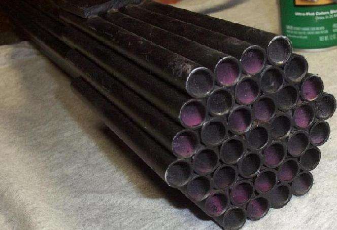
When finished, it will look something like this. The construction doesn't make any sense at first, but it will work out, provided you cut all the pieces to the right length. Notice how it looks like three rings around the original 36-inch tube. Remember that it needs two 1-inch pieces to finish off the sides, also be sure the tubing ends are all properly aligned!
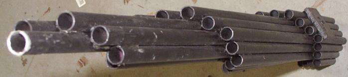
Another (somewhat) finished view. I cleaned the aluminium tubing with a little bit of lye and hot water (DANGER! - Doing that can give you an ouchy if you have the I.Q. of a 2600 subscriber) then I spray painted it with a zinc-chromate primer. Next, I sprayed almost a whole can of black Plasti-Dip spray-on plastic coating on the outside of the tubing. This was done to hopefully help in the reduction of accidental noise vibration pick-up while the microphone is in operation - I think it worked a little bit.
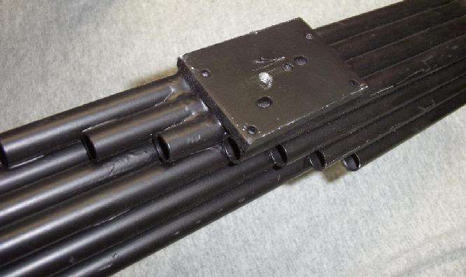
View of the mounting block. It's just a scrap piece of aluminium, with a 1/4-inch (20 TPI) tapped hole, epoxied to the approximate middle of the shotgun mic. This can be used for mounting the microphone tubes to a camera tripod.
Another overall view.
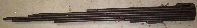
Full view of the shotgun microphone tubes.
These are the components which will be needed to make the "funnel" for the audio amplifier which will attach to the back of the microphone tubes. Clockwise from the the upper left is a PVC 3-inch to 2-inch reducing coupler, a plug-in thingy to add threads to the reducing coupler, and the matching threaded coupler for that part. Next, is some rope caulk, and finally, a high-output piezoelectric microphone element, Mouser (http://www.mouser.com) part number 25LM024. I'm kinda guessing at this point, so if you can think of something better for your own design, use it.
All the PVC parts are painted with a copper "flake" paint to help in the attenuation of any electromagnetic interference.
Use the rope caulk to mount the piezoelectric microphone element inside the threaded plug-in. Secure it from both the front and the back.
Alternate view of the microphone element inside the threaded plug-in.
Rear view of the microphone element inside the threaded plug-in. The isolated (red) pad is the microphone's POSITIVE terminal, the other tab is CASE GROUND.
Then slide the threaded plug-in into the 3-inch to 2-inch reducing coupler. It should look something like the picture.
This is how the PVC parts should look when connected.
Audio amplifier circuit board. Test setup.
Closeup picture of the audio amplifier circuit board. A combination of both surface mount and leaded components are used to reduce space. The red/black leads on the left are for the microphone element. The white/green/brown wire bundle is for the volume control potentiometer. The white/black leads out the bottom are for the speaker and the red/black leads are connected to a 9 Volt battery.
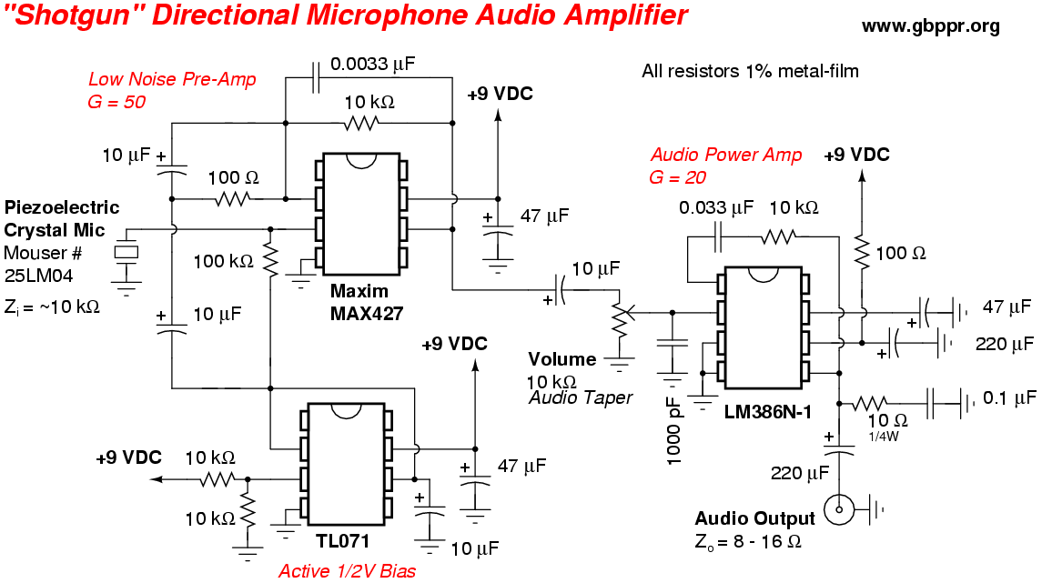
Try to use 1% metal-film resistors, as they offer the lowest noise. Electrolytic capacitors should be of high quality. Digi-Key carries a good Panasonic line. Low value capacitors should be of polystyrene or polypropylene dielectric material. Keep the areas around the feedback resistor/capacitor in the MAX427 clear of any solder flux.
Picture of the audio amplifier board mounted between the threaded PVC adapters. The PVC end cap contains the volume control potentiometer with an integrated on/off switch. The audio output is via a 1/4-inch mono headphone jack. The end cap is taped to the other PVC pieces.
The funnel is fitted to the microphone tubes. You may have to grid the PVC reducing coupler with a Dremel tool for it to fit the tubing. Then pound the coupler onto the tubes with a rubber mallet. It should be a tight fit. Seal the funnel with rope caulk.
Finished microphone. Apply a coat of olive drab paint or some other form of camouflage. It works pretty well, but don't expect any miracles. The audio is quite "tinny" due to the microphone element's poor bass response. Use an external equalizer to correct this. Increase the value of the 10k resistor in the MAX427's feedback to increase the overall amplifier gain.