Project Overview
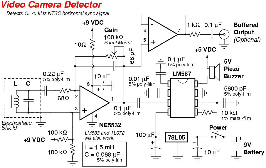
This project consists of a tuned ferrite rod antenna system coupled to a high-gain, low-noise NE5532 dual op-amp which feeds a LM567 tone decoder and piezo buzzer. The ferrite rod antenna is tuned to resonant at around 15.75 kHz, which is the horizontal synchronization frequency for a standard NTSC video signal. The idea is to simply receive, amplify, and recognize this specific synchronization frequency, while rejecting everything else. Any device which is generating or carrying a video signal should be detectable, depending on the amount of shielding and local RF interference. Being able to detect any video device is both good and bad. It's good, in that every television set generates a nice, strong 15.75 kHz signal for testing. It's bad, in that every television set in the immediate area will give you a false "hidden camera" reading. You'll need to take this into account when you are performing your video countermeasures sweep. Physically unplug any TV you find from the AC outlet, as they are never really "turned off." Fluorescent lights and switching power supplies can also give you false readings. You may have to flip a few circuit breakers to do your sweep properly. You'll also want to pick up a TV-B-Gone or two. Heh...
The heart of this device is the ferrite rod antenna. Thankfully, these are now easy to find due to the abundance of "self-setting" clocks. These clocks have an internal radio receiver which is tuned to the WWVB atomic clock broadcast at 60 kHz. You can salvage a useable ferrite rod antenna from an old clock. You can also order a C-MAX CMA-60-100 ferrite rod antenna from Digi-Key, part number 561-1001-ND for only $1.53. The C-MAX ferrite antenna from Digi-Key will be used for this particular project. This ferrite antenna will need to be slightly modified to receive the 15.75 kHz signal. The stock antenna comes with a 4700 pF capacitor in parallel with the antenna's main winding, which equals approximately 1.5 mH. This results in a tank circuit which resonates at around 60 kHz. You'll have to replace the 4700 pF capacitor with a 0.068 µF capacitor instead. A high-quality, 5% tolerance polystyrene capacitor is recommended. One little quirk, though. The winding on my C-MAX ferrite antenna measured around 1.74 mH. This required a 0.056 µF capacitor to lower the resonant frequency to 15.75 kHz. You may wish to double-check the value of the ferrite antenna's winding before you begin this project, especially if you are using a salvaged ferrite rod antenna.
An option to this design will be a buffered output of the op-amp's received signal. This could be useful for adding a small audio amplifier to drive a pair of headphones so you can listen to the received signal. An even better idea would be connecting it to a computer soundcard for further, and much more powerful, signal processing, filtering, decoding, etc.
Another possible use for this device is to locate the video cameras which are often used by terrorists to record their attacks for later broadcast. It's no secret the war profiteers in the liberal media need to fake stories to help extend wartime efforts in their desperate attempts to gain more advertising money from their failing "news" medium. Networks like CNN and NBC are perfect examples of this. CNN is an "international news" network which, of course, is liberal-speak for "our shareholders are from shady Arab countries." Here are a couple of stories they won't be covering:
"Given the current rise in enemy sniper ops, especially since CNN aired the footage of Jaysh al Islami (Islamic Army) killing American soldiers in Baghdad, proper employment is paramount."
--- Excerpt from Soldier of Fortune, February 2007 discussing sniper operational deployments.
"I talked to a infantry grunt who escorted a CNN reporter when we were in Iraq in '05-'06. She kept asking the locals "How do you feel about the Americans?"... positive response. She wasn't happy... "Now that you have no electricity How do you feel about the American's in Iraq?"... again, positive response... she STILL wasn't happy. She kept asking the same question 10x, different ways until she got a moderatively negative answer and ran with that. Those poor soldiers just sat there shaking their heads."
--- Excerpt from http://hotair.com/archives/2007/01/24/shameless-ap-journalistic-crime-of-the-day.
If you detect a strong video synchronization signal coming from a group of ragheads wearing CNN jackets, shoot the bastards.
Video Detector Block Diagrams
Construction Notes & Pictures
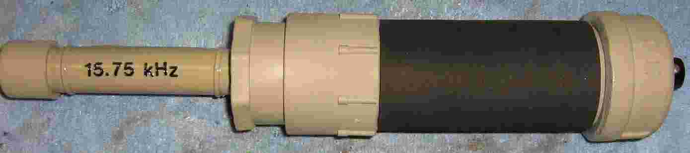
Parts overview. The ferrite rod antenna will be mounted inside a five inch piece of 1/2" diameter PVC pipe. The detector PC board will be mounted inside a five inch piece of 1.5" diameter metal pipe. The PVC and metal pipe sections are connected together via a threaded reducing coupler. A metal pipe end cap will be used to mount the gain control potentiometer / power switch.
The ferrite rod antenna will be supported inside the PVC pipe with a series of O-rings and plumbing washers. Get an assortment pack of plumber's washers at the hardware store and dig through them to find the best ones.
Closeup picture of the stock C-MAX CMA-60-100 ferrite rod antenna. This is Digi-Key part number 561-1001-ND. The antenna's winding is in parallel with a 4700 pF capacitor.
Replace the 4700 pF capacitor with a 0.068 µF or 0.056 µF capacitor. This lowers the ferrite rod's resonant frequency to around 16 kHz. Note the O-ring to secure the fine wires.
Place the ferrite rod antenna inside the piece of 1/2" diameter PVC pipe and secure the antenna using rope caulk. The other end of the pipe is secured with a 1/2" PVC end cap. Be sure the brittle ferrite antenna maintains its "cushion" of rubber washers or O-rings.
Connect the PVC pieces together like so. Note the small hole in the reducing coupler. This will be for a grounded electrostatic shield around the ferrite antenna.
Make the circuit up like so. A circular PC board layout was used so it can easily mount inside the metal pipe. The schematic and the components shown in the photo differ due to experimentation. Use the components as shown in the schematic.
Mount the circuit board on a little L-bracket using some epoxy putty. You may also attach the 5 volt piezo buzzer to the back of the circuit at this time. Be sure you use a real piezo buzzer and not a speaker. A piezo buzzer contains all the necessary tone driver hardware. In addition to the piezo buzzer, a LED or small vibrating motor could also be added.
The metal end cap will be used to hold the gain control potentiometer / power switch. It will also hold a 3/32" mono jack for the buffered output signal. Since the end cap has a slight curve to it, it will look kind of funny when drilled. Use a large-diameter drill bit to countersink the holes so you can access the mounting hardware. Also, double-check that the slight curve to the end cap doesn't short out the terminals on the potentiometer inside the cap. Add a small piece of art foam if it does.
Mount the detector circuit board inside the metal pipe by using epoxy putty pressed over the L-bracket. Note the wires coming from the ferrite antenna. Be sure there is enough slack so you can screw the PVC section to the metal pipe. Also be sure the wires are twisted together to maintain electrical balance.
Next, is the electrostatic shield. This will consist of a piece of copper foil which will partially surround the ferrite rod antenna. This shield is to prevent the antenna from becoming unbalanced by forcing the capacitance along the length of the ferrite rod to be at an equal ground potential.
It's made from a 3.5" by 2.5" piece of #44 gauge copper foil glued around the ferrite antenna PVC pipe section. Ideally, the shield should extend over the length of the ferrite rod by an inch or so. You may wish to experiment with this setup.
The foil is attached and a ground wire is soldered to it. A few zip-ties help to secure the copper foil in place.
Finished overview. Fill the metal pipe with pieces from a cut up sponge to secure the 9 volt battery and additional wiring inside it. Make sure there is enough slack in the control wiring to allow the metal end cap to be screwed on. Apply a good coat of spray paint and some art foam around the handle to make it look all pretty.
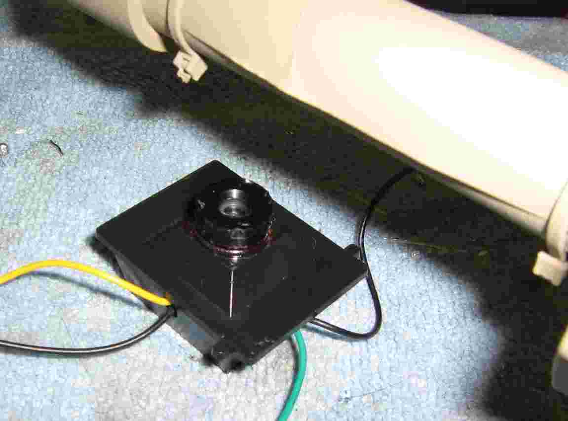
Does it work? It does detect cameras and TVs quite well, but the range isn't too great. Well under a foot. The maximum detecting range will come along the ferrite rod antenna's axis. There are sharp nulls on each end, just like a magnet.
The CMOS camera shown above started to "chatter" the piezo buzzer at around a distance of three inches. Possible detector improvements include adding much more gain in the op-amp section and switching to an op-amp with better ultrasonic capabilities. A Maxim MAX437 would be a good choice for this application.
Schematic
Notes
- Higher resolution pictures and the original project article are available in GBPPR 'Zine Issue #37
- GBPPR Video Camera Detector in Operation (YouTube)
Other Related GBPPR Projects:
- Lamp Flasher For Detecting Hidden Cameras
- Video Camera Jammer
- Detecting Hidden Video Cameras
- Device to Cause RF Interference in Electronics


