Overview
The idea is to salvage a 10.5 GHz Gunn oscillator/transceiver (Gunnplexer) from an old automatic door opener or police radar gun. You'll then add a high-gain pre-amplifier and comparator circuit after the Gunnplexer's internal mixer output to detect any motion via the Doppler effect. The Gunnplexer is used as a RF "illumination" device and the mixer output is a low-frequency signal equal to the amount of Doppler shift in the target's motion. Since the Gunnplexer samples both the transmitted and received 10.5 GHz signal, the received (reflected) signal of any target in motion will impart a slight frequency shift via the Doppler effect. This output "beat" frequency can also determine the speed of the target. If you have ever gotten a speeding ticket, well, now you know how... This particular device is capable of detecting motion from anything like a person walking to, in theory, just a simple heartbeat.
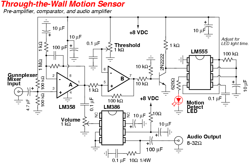
The post-mixer pre-amplifier stage will be made around the commonly available LM358. After amplification, the signal will be sent to the comparator stage, made from the second op-amp in the LM358. This is also where you can set the threshold for the motion detection trigger. A sample of the pre-amplified signal will also be sent to a LM386 audio power amplifier. This will allow the use of headphones to help weed out any "false positives" from electrical interference. Induced electrical interference will sound like a loud 60 or 120 Hz buzzing tone, with fluorescent lights being the biggest problem. The "high" output from the comparator stage toggles a transistor, which, in turn, triggers a 555-timer wired for monostable output. The output pulse from the 555-timer then controls a LED or other alerting device. When any motion is detected which is greater than the comparator's threshold setting, the 555-timer will trigger, illuminating the LED for a second or so.
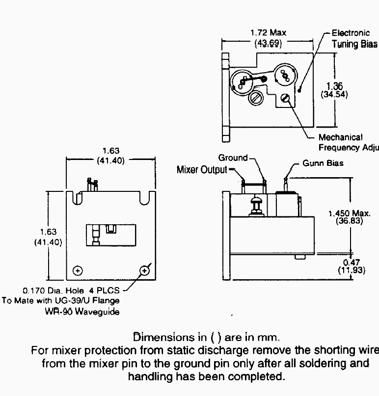
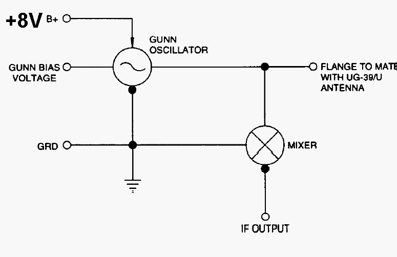
The heart of this device is the 10.5 GHz Gunnplexer. New Gunnplexers and their associated datasheets can be fairly difficult to track down. The following block diagrams should cover the pin-outs on most of the basic models from Alpha and M/A-Com. The Gunn bias voltage is usually around +8 VDC (200 mA) and the varactor frequency tuning voltage (if present) is usually between +1 and +20 volts. A new Gunnplexer might have a static shorting wire from the mixer output to ground. You'll need to replace this with a 1,000 or 2,200 ohm resistor. Mechanically tuning the Gunnplexer's cavity can usually swing the output frequency from 9.5 to 11 GHz. Varactor tuning can be used to electrically swing the output 100 MHz or so. This is useful for modulating the output RF signal or for adjusting the frequency to avoid interference from other devices in the same band.
M/A-Com Gunnplexer Block Diagrams & Notes
Doppler Frequency Shift Equation
       Fd = (2 * Fo) / c

  Fd = Doppler Shift  (Hertz)
  Fo = Original Transmit Frequency  (Hertz)
   c = Speed of Light  (299,792,458 meters per second)
Using a 10.5 GHz Gunnplexer, the on-axis, two-way Doppler shift would be 70 Hz each meter per second (31.3 Hz each mile per hour) of the target's speed.
The Doppler shift frequency is same whether the target is moving towards or away from the Gunnplexer.
Pictures
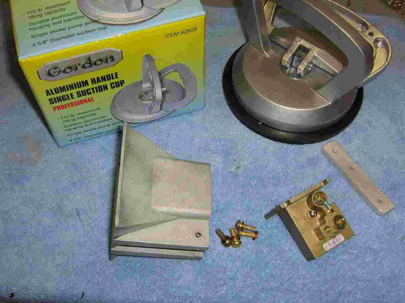
Overview of the major parts used.
An "Aluminum Handle Single Suction Cup" from Harbor Freight Tools (#92825) will be used to mount the Gunnplexer and its associated electronics. This will allow the motion detection device to be mounted to a smooth surface without the worry of any vibrations causing false triggers.
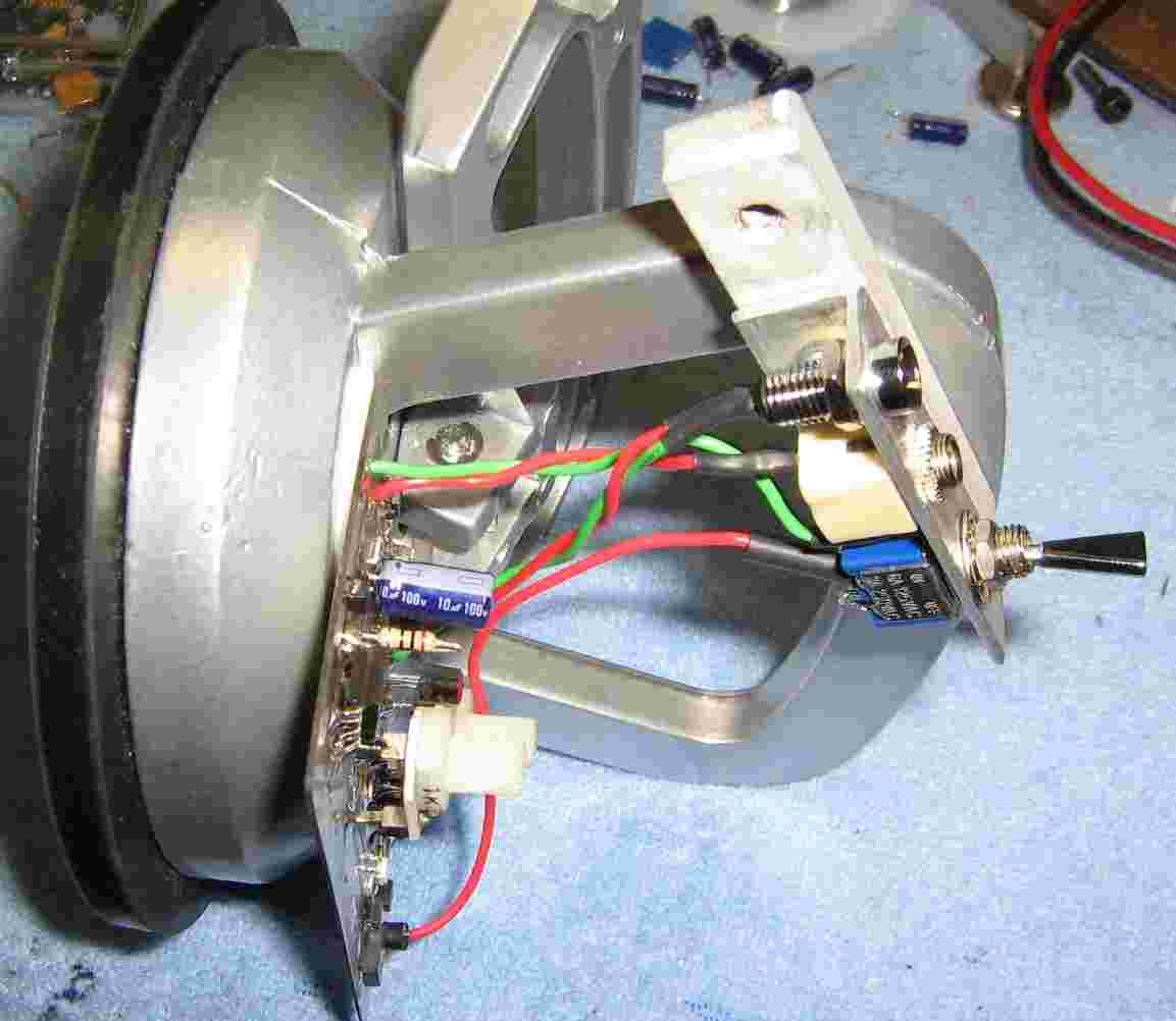
The Gunnplexer is a M/A-Com MA87728 and the horn is from an old automatic door opener.
The small piece of aluminum bar stock on the right side will attach to the suction cup's handle to hold the Gunnplexer.
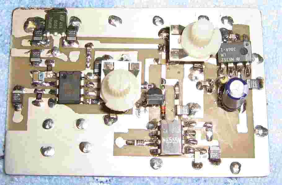
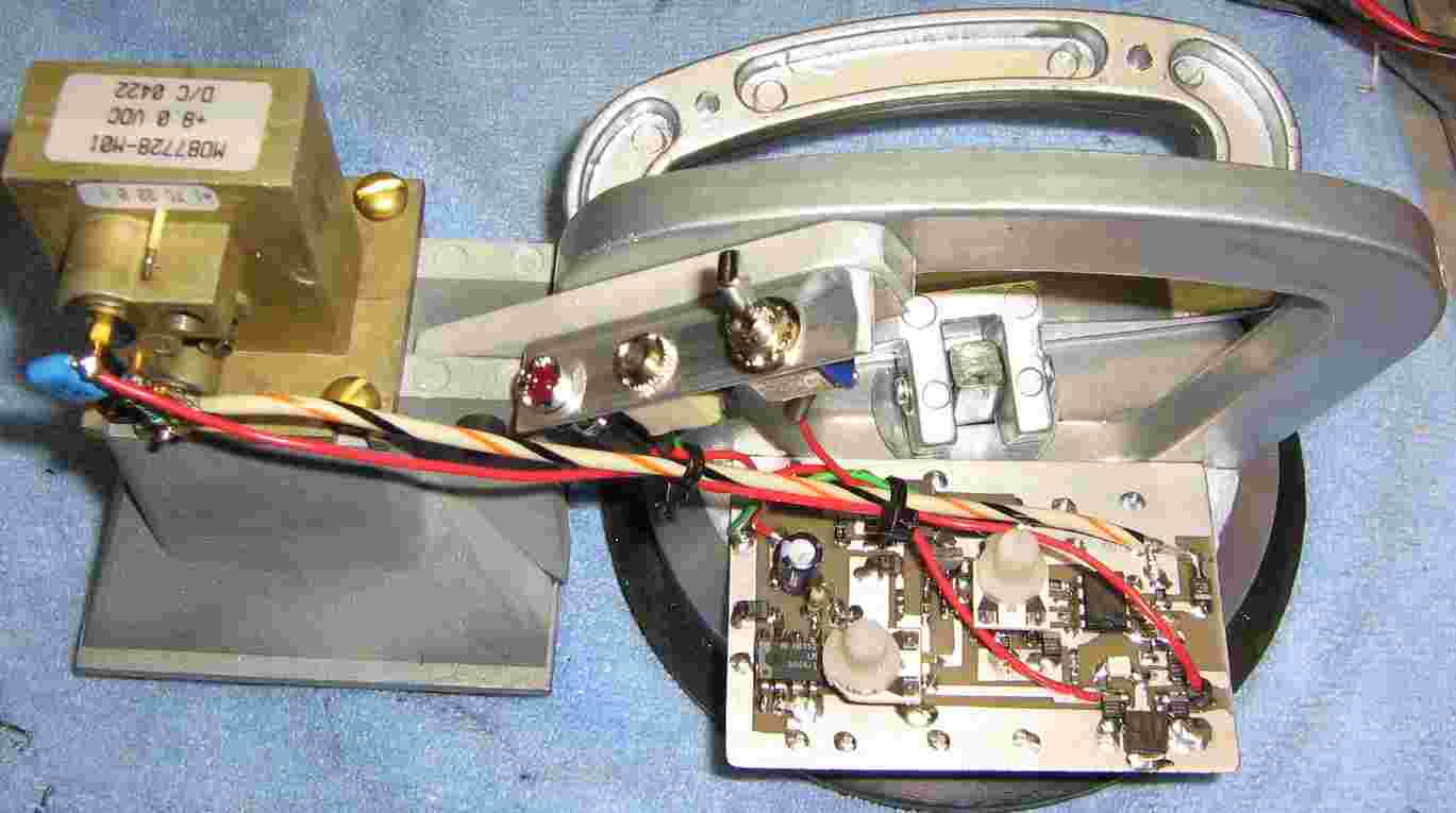
Pre-amplifier and audio amplifier circuit board.
Construction of the board is not too critical, but you'll want to have a large ground plane and proper EMI filtering. Some components and traces in the above photo are different from the schematic due to various changes. The schematic will be accurate.
The LM358 is the 8-pin IC on the left, the comparator threshold setting potentiometer is in the middle. The 555-timer is the 8-pin IC on the bottom-right, and the LM386 is on the upper-right with its input volume potentiometer next to it. A 78M08 voltage regulator is in the upper-left. The voltage regulator is for both the pre-amplifier circuit board and the Gunnplexer bias.
The LM358 pre-amplifier is set to only amplify below 1,000 Hz or so. You can adjust the op-amp's feedback and gain setting components to reduce false triggers or electrical interference. Additional circuit improvements would include using a higher quality low-noise op-amp instead of the LM358 and 60 or 120 Hz notch filters after the pre-amplifier.
It is even possible to get target range information if you modulate the Gunnplexer's varactor with a triangle wave, then compare the phase relationship with the received reflected signal.
And yes, modulating the varactor with a 1,720 Hz sine wave will make a X-band police radar gun read "55 MPH."
A little piece of aluminum angle stock is used to hold the motion indicator LED, a 1/8" jack for the headphones, and the power switch.
Attachment of the Gunnplexer and horn assembly to the suction cup handle is via a single #8 screw. The entire Gunnplexer assembly can be tilted up or down slightly by loosening the attachment screw.
Note the 1,000 ohm resistor from the Gunnplexer's mixer output to ground. This provides a proper DC return for the mixer diode bias.
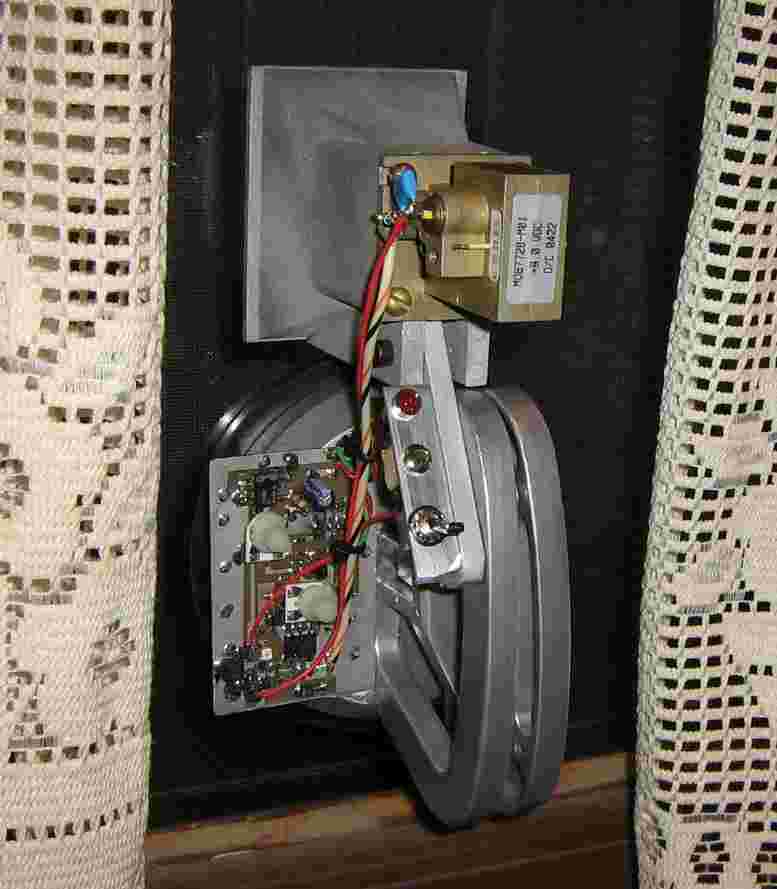
Completed through-the-wall motion detection device.
The Gunnplexer's mixer output is via shielded wire and the +8 VDC Gunn diode bias is straight off the 78M08 regulator's output. A 0.1 µF capacitor is across the Gunn diode bias pin to ground.
Since this is was mostly a test setup, nothing was properly shielded and there is no room for batteries. The device was powered from an external +12 VDC battery pack.
Through-the-wall motion detection device attached to a door window.
Since the device is very sensitive to any motion, you'll want to attach it to something solid so it doesn't move. You can moisten the rubber of the suction cup for better attachment to some wood surfaces. It should be noted that this device does not work through metal doors and brick walls can severely attenuate the signal.
The unit also takes a few seconds to "warm up" after power is applied. You'll also want to experiment with the threshold settings ahead of time to get a feel for the range of this device.
A video showing the testing of this device is available here: Through-the-Wall Motion Detection Device (WebM)
Schematic
Notes & Datasheets
- Higher resolution pictures and the original project article are available in GBPPR 'Zine Issue #57
- Radar Flashlight for Through-the-Wall Detection of Humans
- Investigation into Non-Visual Surveillance Devices (711k PDF)
- Radar Sensing of Heartbeat and Respiration at a Distance with Security Applications Abstract
- Detection and Tracking of Moving or Trapped People Hidden by Obstacles using Ultra-Wideband Pseudo-Noise Radar (939k PDF)
- Wideband Synthetic Aperture Beamforming for Through-the-Wall Imaging (122k PDF)
- Surveillance Through Concrete Walls TM 2003-233 (4.2M PDF)
- Remote Heart Rate & Breathing Rate Detection
- Wave-Sense Through-Wall Motion Detection (YouTube)
- Cambridge Consultants Prism 200 Handheld through-wall radar.
- RealTronics WallVision
- L-Band Through-Wall Microwatt Radar Senior design NRL-sponsored project by Michael Volz. (625k PDF)
- New Device Will Sense Through Concrete Walls Radar Scope press release.
- Magic Backpack Can See Through Walls
- Using WiFi to See Through Walls
- RadarVision2 in Operation Video showing the operation of a RadarVision2 through-the-wall radar device. (YouTube)
- Ultra Wideband Radar for Through-Wall Detection from the RADIOTECT Project (729k PDF)
- Through-Wall Tracking Using Variance-Based Radio Tomography Networks (440k PDF) (Hack a Day)
- Radar Flashlight Project Promises COTS-based Human Vital Signs Sensor (Additional Info)
- Radar Speed Controller This false-target generator is ideal for testing and calibrating radar speed guns. By Anthony Stevens in Radio Electronics, August 1986. (2M PDF)
- Dual-Band Smokey Detector X- and K-band speed radar detector, by Stirling Olberg
- Gunn and IMPATT Microwave Devices 73 Amateur Radio, October 1987. (2M PDF)
- The Solfan Special 73 Amateur Radio, January 1987. (670k PDF)
- Solid State Devices for 1 GHz Radio Electronics, August 1981. (539k PDF)
- The Care and Feeding of Gunnplexers QST, April 1983. (438k PDF)
- Annie Get Your Gunnplexer! QST, September 1993. (224k PDF)
- Remote Systems ECM 5446 Radar Jammer (Video)
- Terabeam HGM & HGV Gunn Oscillators (139k PDF)
- M/A-Com MA87728 10.5 GHz Gunnplexer (148k PDF)
- M/A-Com MA87729 24.1 GHz Gunnplexer (116k PDF)
- Microwave Device Technology MO8000 & MO9000 Gunn Oscillators
- Spacek Labs Gunn Oscillators
- Intrusion Alarm Patents
- Through-the-Wall Detection of Stationary Human Targets Using Doppler Radar (626k PDF)
- L-3 Communications RANGE-R Handheld Through-Wall Sensor
- L-3 Communications RANGE-R Operator's Manual The RANGE-R cycles through a sequence of 120 frequencies in 2 MHz increments from 3.18 GHz to 3.42 GHz. At each of the frequencies, it transmits a maximum 32 mW power level with no modulation. (536k PDF) (Internal Photos) (External Photos) (Test Report)
- Through-the-Wall Sensors for Law Enforcement Market Survey October 2012 (641k PDF)
- Handheld Radar Frequency Scanner for Concealed Object Detection U.S. Patent 6,950,054 (351k PDF)
Other Related GBPPR Projects:
- Passive Resonant Cavity & "Spycatcher" Technical Surveillance Devices
- GBPPR Remote Respiration/Heart Beat Monitor Experiments
- GBPPR Interferometric Surveillance Device Experiments
- GBPPR Doppler Stethoscope for E.O.D. Applications
- GBPPR Radar Experiments
- Police Radar Gun Spoofing Experiments
