You've just got done shooting an open-borders politician in the head... You now need to make your quick escape - without drawing attention from any of the local authorities. What you're wishing for is a way to speed in your vehicle without all the hassle of being pulled over or having one of those stupid "Let's make ZOG more money!" photo radars taking your picture. Fret not, as your local Open Source Assassins are currently working on a solution to this problem...
As we learned in the last issue (#57) covering the Through-the-Wall Motion Detection Device, the microwave Gunnplexer in a X-band police radar gun is used as a RF "illumination" device and the Gunnplexer's mixer output is a low-frequency signal equal to the amount of Doppler shift in the target's motion. Since the Gunnplexer samples both the transmitted and received 10.5 GHz signal, the received (reflected) signal of any target in motion will impart a slight frequency shift via the Doppler effect. This output "beat" frequency is what determines the speed of the target. For each mile per hour of target speed, the Doppler shift will be equal to approximately 31.3 Hz.
Since we know the frequency which most police radar guns operate and we can calculate the proper Doppler shift required for different speeds, we can also make that radar gun display just about any speed we wish. We'll do this by transmitting on the radar gun's frequency with a signal modulation that equals the required Doppler shift. Say we want some cop's X-band radar gun to always display "65 MPH." Well, all you'll need to do is modulate your 10.5 GHz Gunnplexer with an audio signal of around 2,034 Hz. Most Gunnplexer sources already have a "varactor bias" pin which makes modulating the output RF signal quite easy.
While this particular device is very experimental and still in development, the construction and operation will be simple. A standard 32.768 kHz watch crystal is configured as an oscillator, with the output "divided-by-two" several times. This signal is picked off via a series of taps at 4,096, 2,048, 1,024, and 512 Hz. One of these output taps is then slightly low-pass filtered and combined with a DC offset via a potentiometer. The combined audio signal/DC offset is then connected to the Gunnplexer's varactor bias pin. Since not all Gunnplexer's have varactor tuning/modulation pins, you may have to apply the audio modulation directly to the Gunnplexer's Gunn diode bias line. This method, and schematic, are shown in the various older copies (when it was good) of the ARRL's Handbook for the Radio Amateur, so it won't be covered here.
The operational idea is that the Gunnplexer's output 10.5 GHz signal will be modulated with the proper Doppler shift to override the weak reflected RF signal from the target vehicle. You are essentially transmitting your own Doppler-shifted RF signal directly into the police radar gun. Since a X-band police radar has a Doppler shift of approximately 31.3 Hz per mile per hour of target speed, the 2,048 Hz and 1,024 Hz clock signals can be used to "spoof" vehicle speeds of approximately 65 and 35 miles per hour, respectively. You can use the other clock taps for experimenting or for spoofing operations on the higher-band (24 and 36 GHz) radar gun frequencies.
     Fd = (2 * Fo) / c

  Fd = Doppler Shift  (Hertz)
  Fo = Original Transmit Frequency  (Hertz)
   c = Speed of Light  (299,792,458 meters per second or 670,616,629 miles per hour)
Using a X-band (10.525 GHz) Gunnplexer, the on-axis, two-way Doppler shift would be 70 Hz each meter per second (31.3 Hz each mile per hour) of the target's speed. Newer Ka-band (33.4 - 36 GHz) police and photo radars will have a Doppler shift equal to approximately 100 to 109 Hz per mile per hour of target speed.
Most Ku-band radars operate around 13.45 GHz, so the Doppler shift is around 40 Hz per mile per hour of target speed. Example: 55 MPH is 2,200 Hz.
Most K-band radars operate around 24.125 GHz, so the Doppler shift is around 72 Hz per mile per hour of target speed. Example: 55 MPH is 3,960 Hz.
Most Ka-band radars operate around 34.7 GHz (35.5 GHz for the photo radars), so the Doppler shift is around 104 Hz per mile per hour of target speed. Example: 55 MPH is 5,720 Hz.
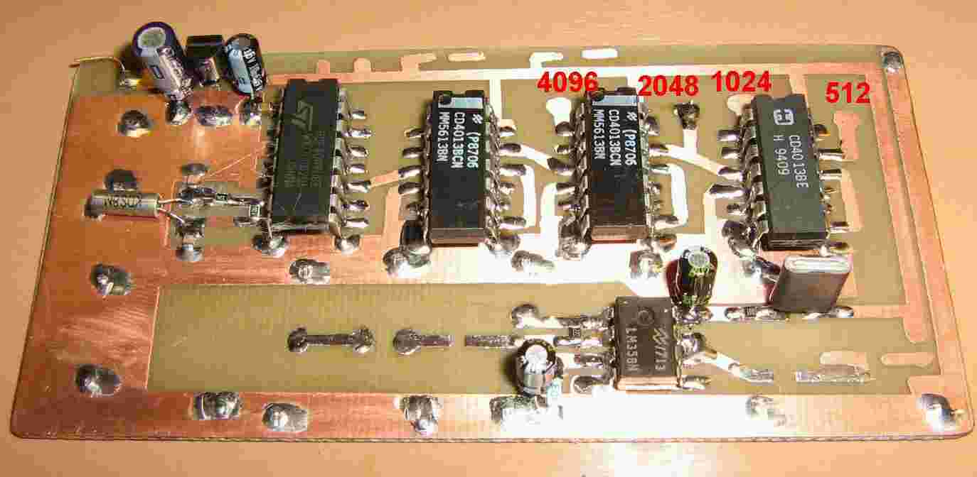
Clock generator circuit board.
A 78L08 voltage regulator and input voltage filtering is on the upper-left.
The 8-pin IC on the left is the CD4049 hex buffer with a 32.768 kHz watch crystal setup as an oscillator. The CD4049's 32.768 kHz clock output is then sent to a series of CD4013 dual D flip-flops to be further divided down. Each flip-flop divides the incoming signal by two, so you end up with a series of taps at 16,384, 8,192, 4,069, 2,048, 1,024, and 512 Hz. Clock oscillator values other than 32.768 kHz can be used to alter the required final output signal frequency.
An op-amp low-pass filter was experimented with, but found not necessary for cleaning up the Gunnplexer's modulating signal. A simple resistor/capacitor combination will be used instead.
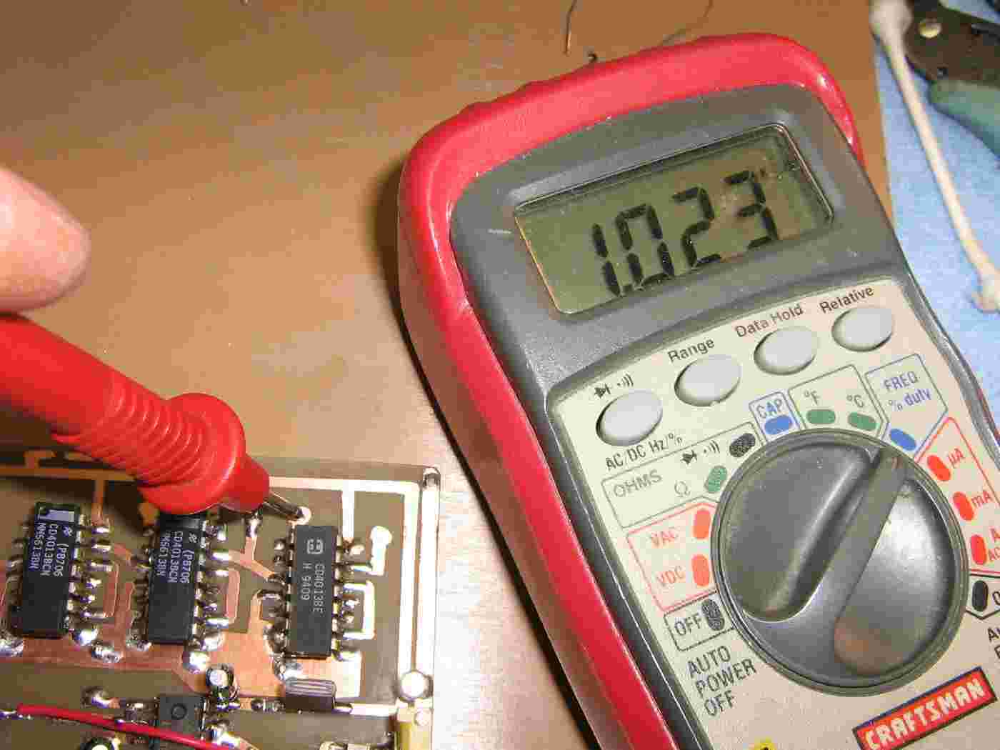
Checking the output frequency of the 1,024 Hz clock tap.

Oscilloscope view of the 32.768 kHz clock output. 2 volts per division vertical and 20 µS per division horizontal. The circuit was initially run at +5 VDC, but using +8 VDC allows for a greater frequency swing on the Gunnplexer.
You may have to fiddle with the value of the 330 kohm resistor or the crystal's loading capacitors if the circuit doesn't oscillate on startup.
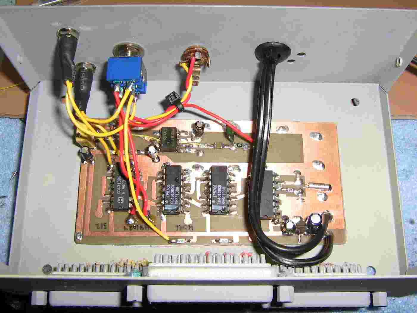
Inside case overview.
The case is an old printer switch with the circuit board attached via double-sided tape.
The DC input power is via a standard, fused automotive cigarette lighter plug.
The Gunnplexer's varactor modulating signal and DC offset are sent to a panel-mount mono 1/8" jack.
A DPDT switch with a center-off position is used to select the required spoofing speed. The two LEDs indicate the switch's status.

Finished outside case overview.
12 VDC cigarette lighter plug is on the left, Gunnplexer varactor output is in the middle, and the speed select switch and LEDs are on the right.
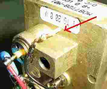
Example of a M/A-Com Gunnplexer varactor bias pin. The input is +1 to +20 volts with about 50 MHz of overall tuning range.

Test setup.
Using a salvaged Hot Wheels Radar Gun, the display has been spoofed to display 32 miles per hour.
Also, for some reason, the "65 mile per hour" rate didn't work.
Since I don't have a real X-band police radar gun to test this on, it'll all just be experimental right now.
The Gunnplexer may need to be tuned to slightly, either mechanicaly or electronically, to be on the right transmitting frequency.