While Edward Snowden's revelation that the Kenyan-Muslim-Marxist-usurper Obama regime was using the NSA to spy on Americans was no surprise to anyone with half a brain, it did help to shed light on some types of sophisticated technical surveillance techniques which have been known to those "in the field" for while. One of the neatest is an improvement on Leon Theremin's resonant cavity bug which was planted in the gift of an U.S. Great Seal, and was presented to U.S. Ambassador Averill Harriman in 1945 by Russia. The "opening" of the resonant cavity was covered with a thin metal-foil diaphragm which deflected in the presence of sound waves. When illuminated with unmoduated RF carrier, the cavity would resonant and rebroadcast a modulated (phase and a little amplitude) version of the illumination carrier. Subtract (mix) that signal with a portion of the unmodulated transmitted carrier frequency, and your left with a baseband signal containing the room audio. As quoted from the NSA's own sales brochure:
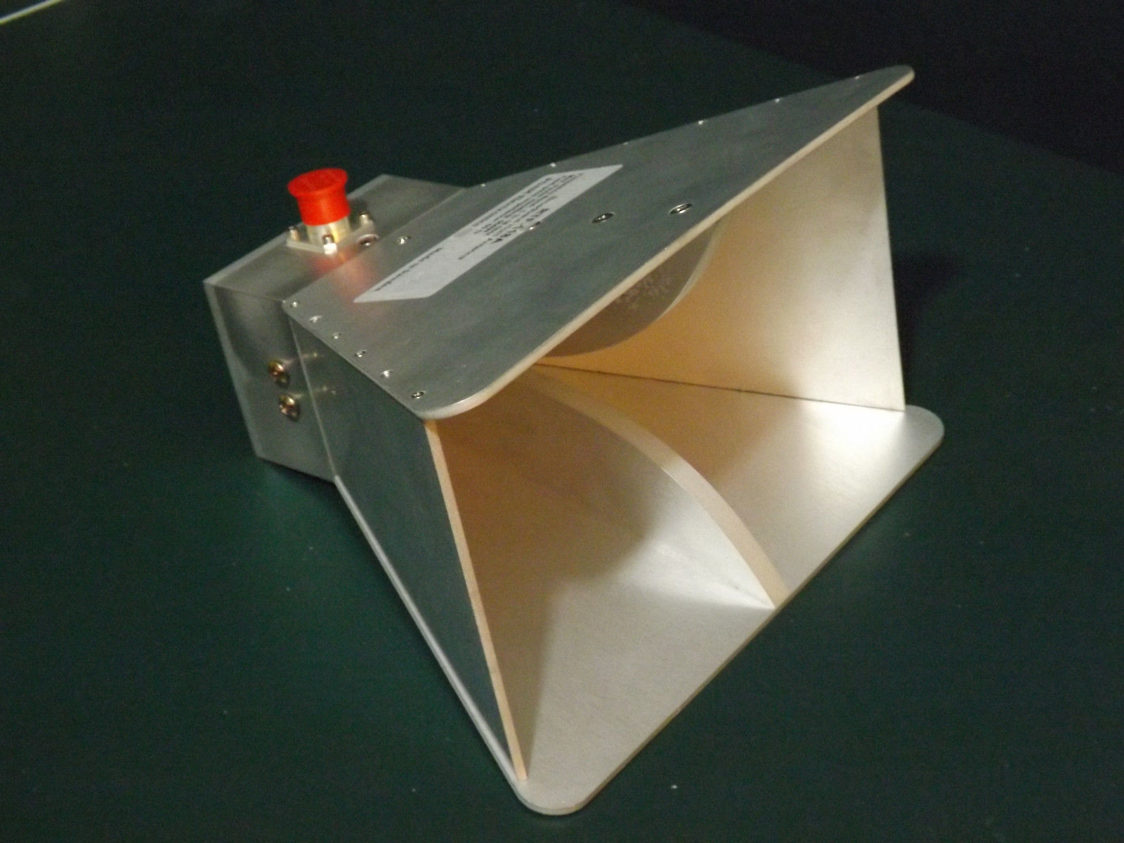
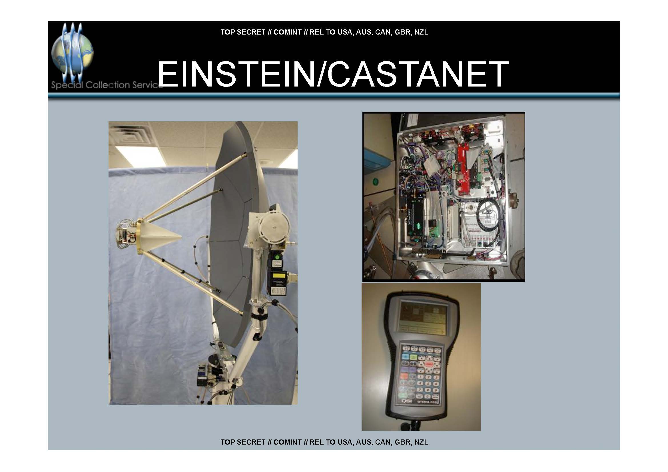
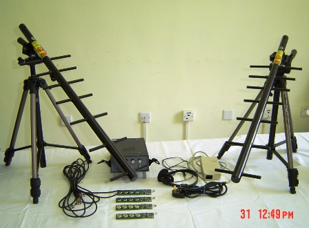
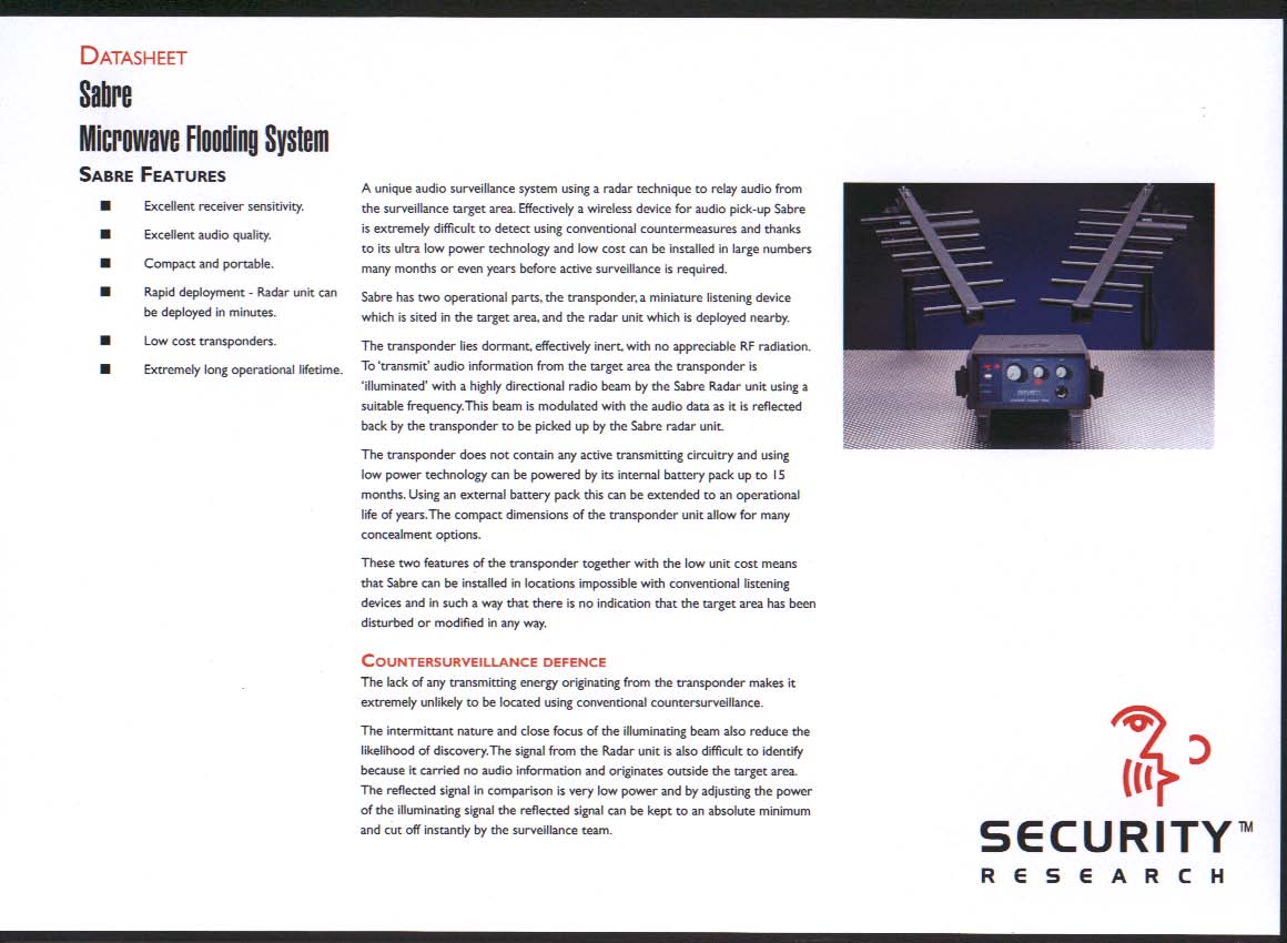
"The radar unit [PHOTOANGLO] generates an unmodulated, continuous wave (CW) signal. The oscillator is either generated internally, or externally through a signal generator or cavity oscillator. The unit amplifies the signal and sends it out to a RF connector, where it is directed to some form of transmission antenna (horn, parabolic dish, LPA [log-periodic antenna], spiral). The signal illuminates the target system and is re-radiated. The receive antenna picks up the re-radiated signal and directs the signal to the receive input. The signal is amplified, filtered, and mixed with the transmit antenna. The result is a homodyne receiver in which the RF signal is mixed directly to baseband. The baseband video signal is ported to an external BNC connector. This connects to a processing system, such as NIGHTWATCH, an LFS-2, or VIEWPLATE, to process the signal and provide the intelligence."
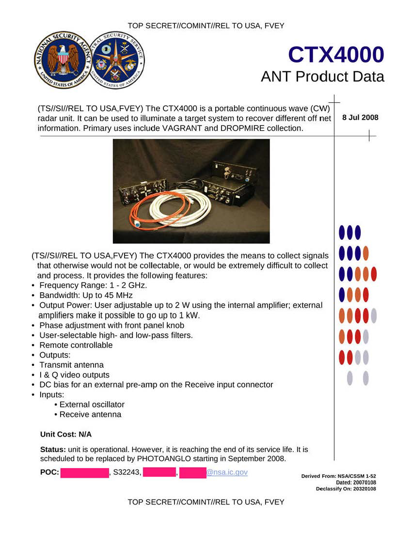
CTX4000
The NSA's PHOTOANGLO unit appears to be an updated version of their CTX4000 system, which is pictured in the leaked secret brochure. The operating frequency range is 1-4 GHz. The use of lower illumination frequencies allows much deeper penetration into obstructed areas, such as concrete blocks or other "shielded" areas. From the brochure: "The CTX4000 provides the means to collect signals that otherwise would not be collectable, or would be extremely difficult to collect and process." The output RF power is adjustable up to 2 watts, but there is a 1 kW external amplifier option for those difficult embassy SCIFs (or rezidentura) or to remotely trickle-charge batteries via an additional antenna/diode rectifier circuit.
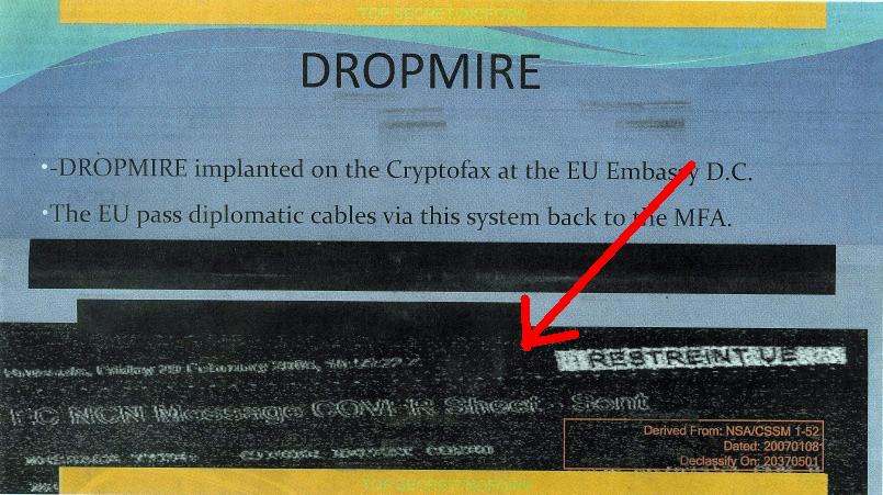
The baseband output(s) from these units is what's refered to as "video output." This is a mostly a historical term, and does not mean the output is a "real" video signal. The baseband outputs are referred to as I&Q, for "in-phase" and "quadrature-phase," and are basically buffered and amplified outputs direct from the receive quadrature mixers. The real signal processing takes place on these baseband I&Q output signals. By processing the I&Q signals, it is possible to extract all sorts of really neat intelligence, from room audio via any micro-Doppler phase shifts, to intercepting crypto key exchanges (i.e. passive DROPMIRE), or even remotely listening to heartbeats. Unfortunately, I don't have a clue on the software processing side, so we'll have to leave that up to someone else... It should even be possible to run the I&Q signals directly (transformer-coupled) into one of those inexpensive RTL SDR dongles, or as least start there...
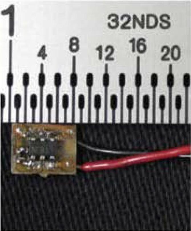
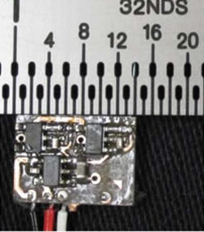
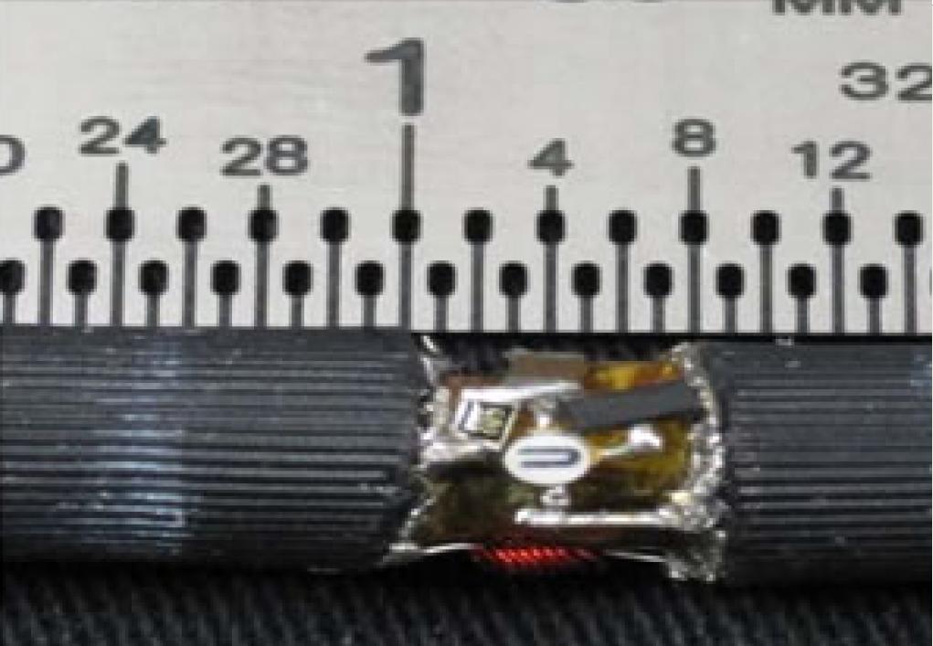
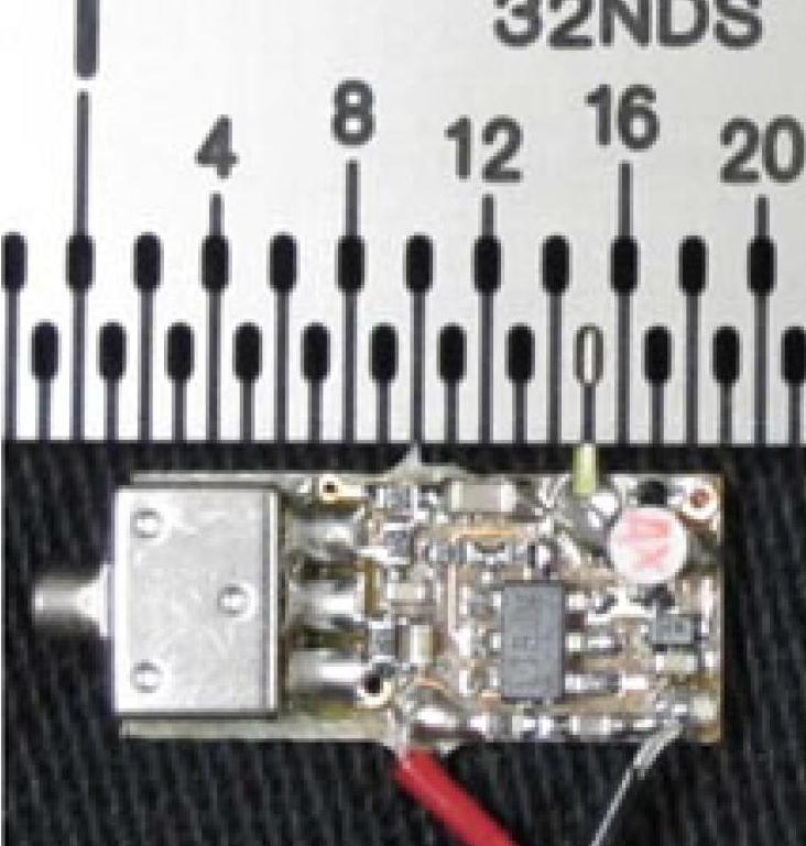
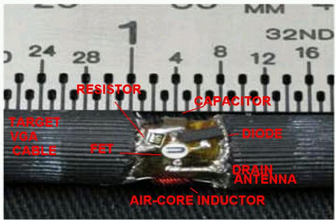
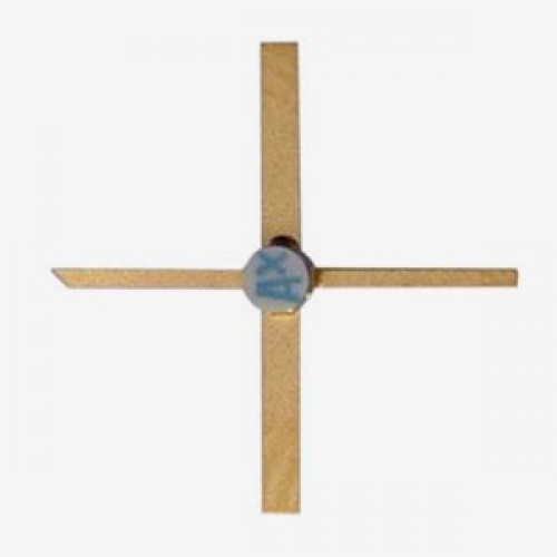
The NSA's improvement on this surveillance techique is to use "radar retro-reflectors" to increase the sensitivy and range of the remote gear. By planting little retro-reflector circuits, it's possible to significantly increase the performance of these surveillance techniques. The NSA's LOUDAUTO device comprises a standard Knowles hearing aid microphone and simple amplifier. The audio output Pulse-Position Modulates (PPM) a low-frequency RF carrier at, say, 100 kHz.
This low-frequency carrier then toggles the gate of a quality RF FET, which basically has antennas for the drain and source. The PPM signal then "chops" the microwave RF illumination carrier to impose the (amplitude) modulation coming from the microphone. The NSA recommends the Rohde & Schwarz FSH-series of handheld spectrum analyzers for receiving and demodulating the reflected RF carrier. You know, using a $9,000 spectrum analyzer to recover a signal you can demodulate for about $100 in parts...
The GBPPR PHOTOANGLO unit described here will be mostly for experimentation, but should be a useable starting point. Most of the RF components were hamfest/eBay finds or salvaged from other gear, so the exact parts may be difficult to track down, but it should be easy to track down suitable equivalents.
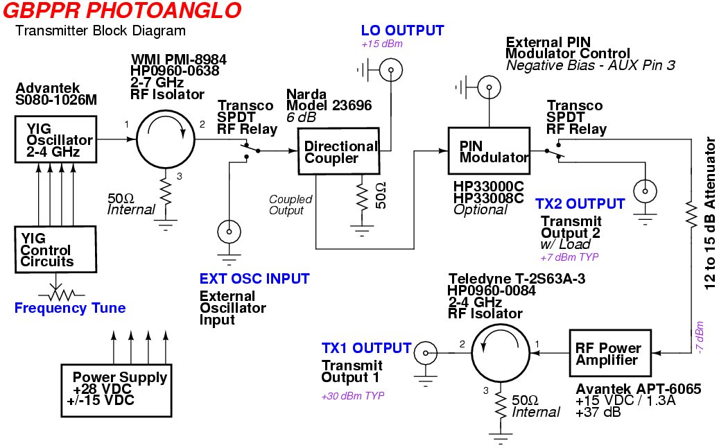
The main oscillator is based around a manually-tuned (potentiometer) Avantek 2-4 GHz YIG-tuned oscillator. This is buffered by an optional wideband 2-7 GHz RF isolator (HP0960-0638). A Transco SPDT RF relay selects between the internal YIG oscillator or an external RF source, such as a synthesized oscillator.
The RF signal then passes through a Narda 6 dB directional coupler to split the signal between going to the receiver's Local Oscillator (LO) and to the transmitter amplifier stage. An optional HP33008C PIN diode modulator can be used to ampltiude modulate the transmitted signal, if so needed.
In real-world surveillance devices of this type, it's common to "chop" up the RF illumination carrrier (AM) to help extract the target intelligence from the noise via a lock-in detector tracking the transmitted modulation phase on the receive side. That will be project for the more advanced student...
The RF signal then enters another Transco SPDT RF relay to select the use of an internal 1 watt RF amplifier, or to send the transmit signal "as-is" to a front-panel connection. The RF amplifier is an Avantek APT-6065 wideband (2-6 GHz) amplifier with 37 dB of gain and a P1dB output around +30 dBm. A linear-biased amplifier is required if you amplitude modulate the carrier to prevent distortion.
An optional RF isolator (HP0960-0084) is on the output of the Avantek APT-6065 to prevent any damage in case you forget to hook the transmit antenna up and to increase isolation between stages. The entire transmitter unit is powered by an external supply providing +28, +15, and -15 VDC sources.
A small voltage regulator board will convert the +28 VDC down to +24 VDC for the YIG's heater connection. The raw +28 VDC is used for the Transco RF relays and is also regulated down to +15 VDC for the YIG oscillator itself. Since the Avantek APT-6065 draws around 1.3 amps, it will have its own +15 VDC source from an external power supply.
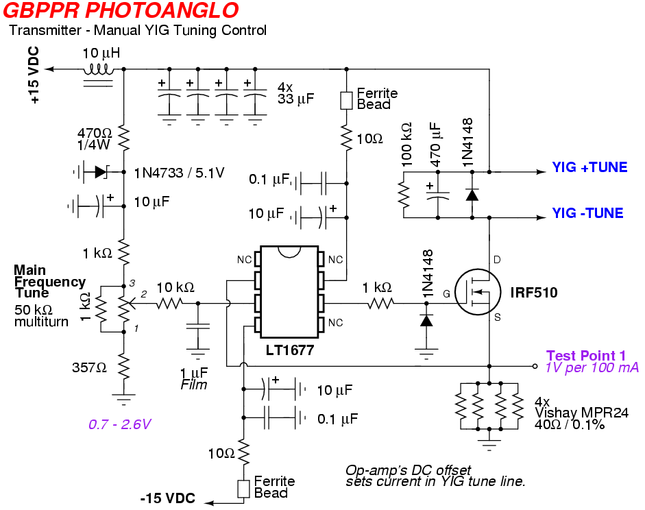
The Avantek 2-4 GHz YIG oscillator has its own control circuit board. This is a standard voltage-controlled, constant-current source based around a LT1677 op-amp and an IRF510 MOSFET. A 50k ohm multiturn potentiometer controls the final output frequency.
The matching GBPPR PHOTOANGLO receiver unit will be described and built in a later article. I ran out of money this month...
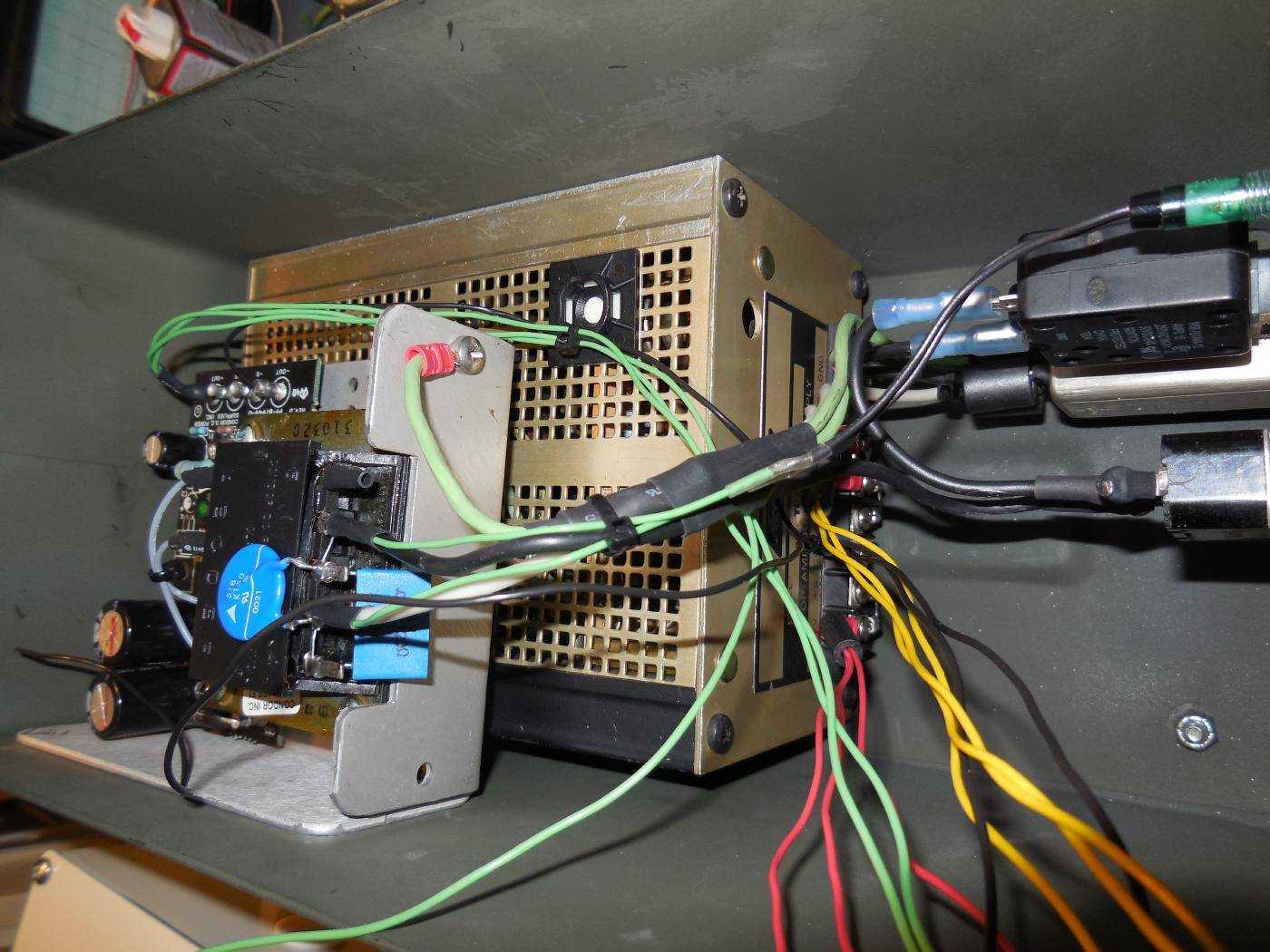
Overview of the GBPPR PHOTOANGLO TX/RX Power Supply.
It's based around an Acopian TD15-160 +/- 15 VDC power supply capable of supplying around 1.6 amps, and a Condor HB28-1-A+ +28 VDC power supply capable of supplying around 1.0 amps.
The Acopain will power the majority of the transmitter and receiver circuits, while the +28 VDC power supply is required for operating the Transco RF relays and will also be regulated down to a clean +15 VDC source for the YIG oscillator.
The blue disk on the transformer's primary is a 150 VAC Metal-Oxide Varistor (MOV) to protect against any voltage transients on the incoming AC mains.
The blue rectangle device on the primary is an optional "snubber." This device consists of a series 120 ohm / 0.033 µF AC-rated capacitor to prevent the generation of a large voltage spike when power is turned off.
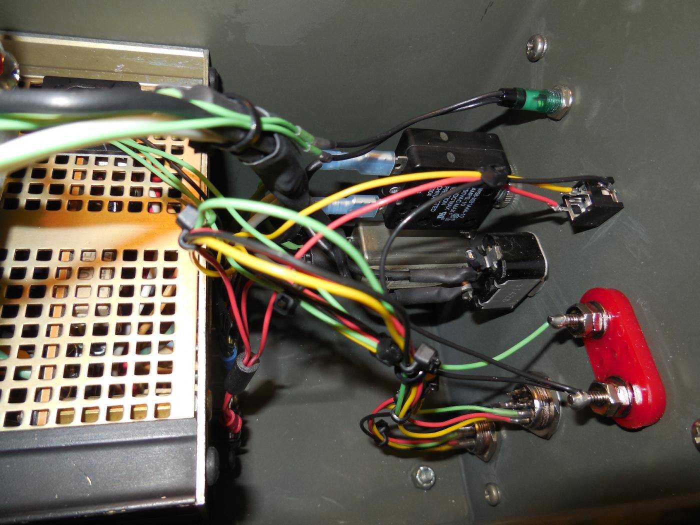
Overview behind the front-panel.
The power supply will be built into an old ammo can.
The 120 VAC mains input is via a standard filtered IEC connector.
The black "hot/live" lead then passes through a panel-mounted 15 amp circuit breaker then goes to a SPST switch for power control.
The white wire is the AC mains "neutral." The green wire is the AC mains Earth ground.
Three optional ferrite beads are on each of the AC mains wires (right after the IEC connector) to help knock down any incoming EMI on the power line.
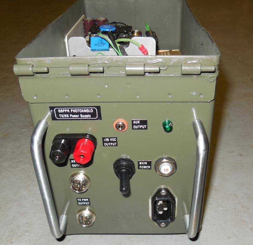
Front-panel overview of the completed GBPPR PHOTOANGLO TX/RX Power Supply.
The banana jack is for an optional +28 VDC output and the 1/8-inch stereo jack (Tip: +15V / Ring: -15V / Sleeve: ground) is also for an optional +/- 15 VDC output. These will be useful for powering external hardware and should be added for future expansion.
There is a green neon lamp for a "power on" indicator.
Two 8-pin microphone jacks are used for the +/- 15 VDC and +28 VDC outputs. Only four of the pins are used on each connector:
Pin      Description                Internal Wire Color
1        +28 VDC Output             Green
2        +15 VDC Output             Red
3        -15 VDC Output             Yellow
4        Ground (Common)            Black
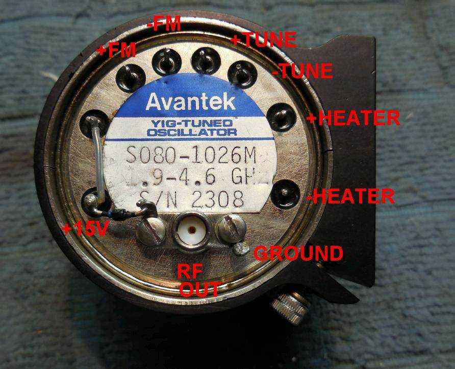
Overview of the Avantek S080-1026M 2-4 GHz YIG-tuned oscillator.
This particular Yttrium Iron Garnet (YIG) oscillator was salvaged from some older microwave gear, so the exact part number doesn't appear on Avantek's website. All their YIGs tend to be quite similar, though.
This particular YIG oscillator tunes from 1.9 to 4.6 GHz with a 20 MHz/mA tuning current. The RF output (SMA jack) is around +16 dBm. Any similar YIG oscillator will work.
The +24 VDC heater connection is optional, but recommended for stable operation. Tie the -HEATER pin to the common ground.
The YIG's +FM and -FM pins are used for applying FM modulation or phase-locking, and they will not used in this application.
Constructing the YIG oscillator control board.
Since YIGs are current-tuned devices, we'll have to use a LT1677 op-amp buffer and IRF510 MOSFET in a voltage-controlled, constant-current configuration to ensure the YIG tuning lines see the proper current.
Four 0.1% 40 ohm resistors in parallel form the current shunt for the IRF510. A 1 volt drop across these resistors equals 100 mA of YIG tuning current.
Since the YIG tunes at 20 MHz per milliamp, the tuning current for the low frequency end of 1.9 GHz is 95 mA. The tuning current for the high frequency end of 4.6 GHz is 230 mA. This corresponds to an equivalent 0.95V and 2.3V voltage drop across the shunt resistors.
A 10-turn, 50 kohm panel-mount precision potentiometer will provide the main frequency tuning.
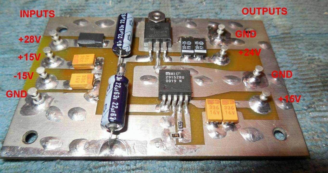
GBPPR PHOTOANGLO transmitter voltage regulator board. The input voltages are from the external power supply.
This takes the incoming +28 VDC and converts it to +24 VDC for the YIG's heater connection and a clean +15 VDC source for the YIG's main power.
The heater draws around 100 mA initially, then backs down as the unit warms up. The YIG's main +15 VDC also draws around 100 mA continuous, separate from the tuning current.
A standard LM7824 voltage regulator is used for the YIG's +HEATER supply. The -HEATER pin is tied to the common ground.
A Micrel MIC29152BU voltage regulator is used for the +15 VDC power. The MIC29152's voltage setting resistors are 6.2 kohm and 560 ohm and should be 1% tolerance.
The +28 VDC input is also used to power the Transco RF relays.
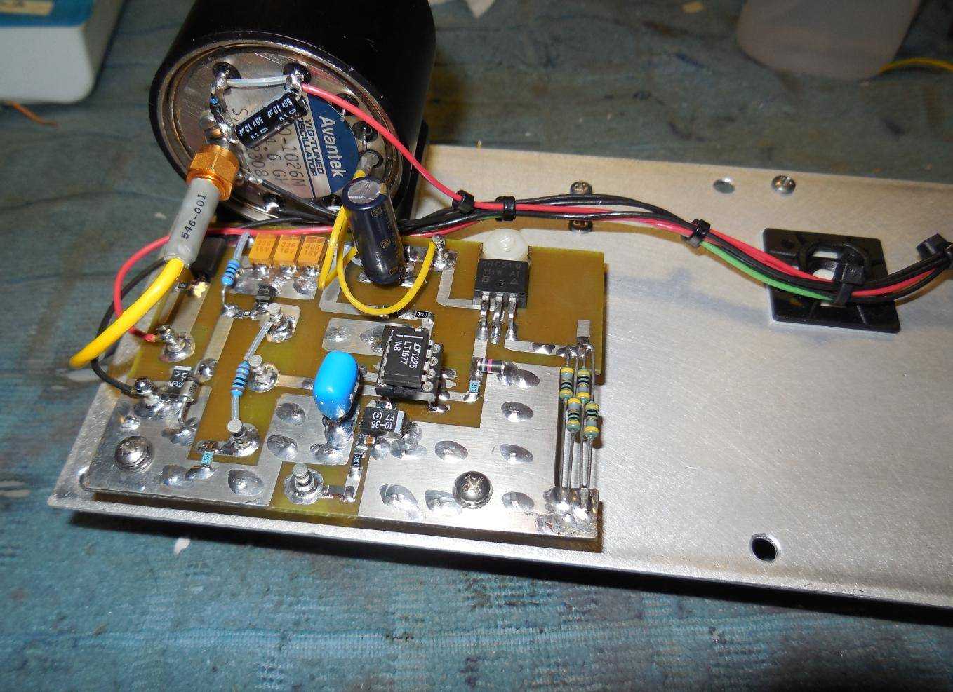
Mounting the Avantek S080-1026M YIG, tuning control board (left), and voltage regulator board (right) onto a piece of sturdy aluminum plate.
The lines to the panel-mounted frequency tune potentiometer are pieces of scrap white Teflon coaxial cable.
The frequency tune potentiometer has a few 1% metal-film resistor in series and parallel to tweak the tuning range from around 0.7 to 2.6 volts and to minimize thermal drifting within the potentiometer.
The YIG oscillator can be mounted via rubber vibration absorption hardware to help minimize the generation of any microphonic modulations which could interfere with the transmitted RF carrier.
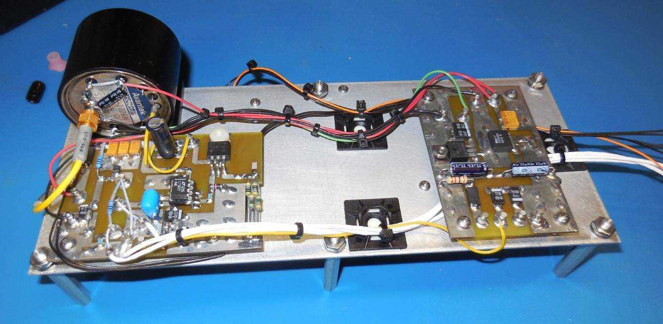
Rear-view of the aluminum mounting plate.
On the output of the YIG is a HP0960-0638 2-7 GHz RF isolator (blue rectangle device on the right). This is to isolate the YIG oscillator from any impedance mismatches further down the RF chain. This device is optional, but recommended.
The output from that isolator is then sent to a Transco 82152-919C74700 SPDT RF relay (port 1). This is to select either the internal YIG oscillator or an external (port 2) RF oscillator. The NSA's PHOTOANGLO does this, so we'll do it too...
The output from the RF relay passes through a Narda Model 23696 6 dB, 2-4 GHz directional coupler. The coupled 6 dB port is sent through the PIN modulator and then onto the RF amplifier.
The pass-through (output) port of the directional coupler is then sent to another optional HP0960-0638 2-7 GHz RF isolator (blue rectangle device on the left) and then finally to a panel-mounted SMA-to-N jack for use as the LO OUTPUT. It should be around +15 dBm, but using the PIN modulator will attenuate the RF power a little bit more.
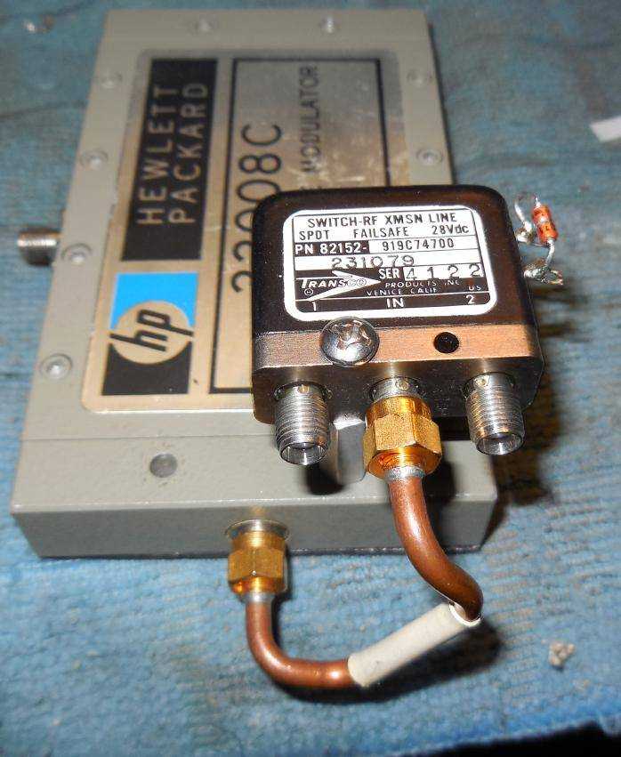
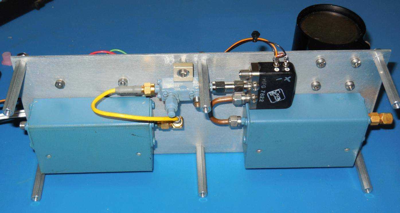
Closeup view of the HP33008C PIN modulator and the Transco 82152-919C74700 SPDT RF relay used for selecting the transmitter output port.
The HP33008 is designed for the 3.7-8 GHz range, but it will still work here for modulating the RF signal with only slightly increased insertion loss. The "correct" modulator would be the HP33000, which covers 1-4 GHz. The HP33001 cover 8-18 GHz. The letter in the part number refers to the isolation range, C = 40 dB, D = 80 dB. They all use a negative bias (100 mA MAX). It's applied via the SMA jack on the "top." I've yet to find a manual for these HP33000-series PIN absorptive modulators, so if you have any info please let me know.
The RF relays require +28 VDC for proper operation. They'll be selected via panel-mounted SPST switches by toggling their ground lines. They can also be controlled externally via the optional AUX CONTROL port.
Mounting the Avantek APT-6065 wideband (2-6 GHz) amplifier and the optional HP0960-0084 isolator on its output.
The Avantek APT-6065 will need to dissipate a bit of heat, so it's mounted to a scrap aluminum plate before attaching to the side of the case. Use a liberal amount of heatsink compound to ensure good thermal contact.
The RF input to the Avantek APT-6065 should be around -8 dBm, so you may have to add an external attenuator on the input.
The final TX1 OUTPUT is via a panel-mounted SMA-to-N jack.
The optional Transco RF relay mounted on the HP33008C PIN modulator can be used to bypass the RF amplifier stage. This connects (port 2) directly to the TX2 OUTPUT which is also a panel-mounted SMA-to-N jack.
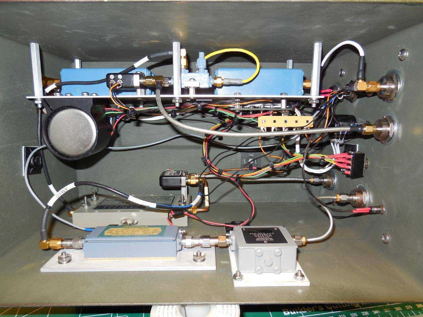
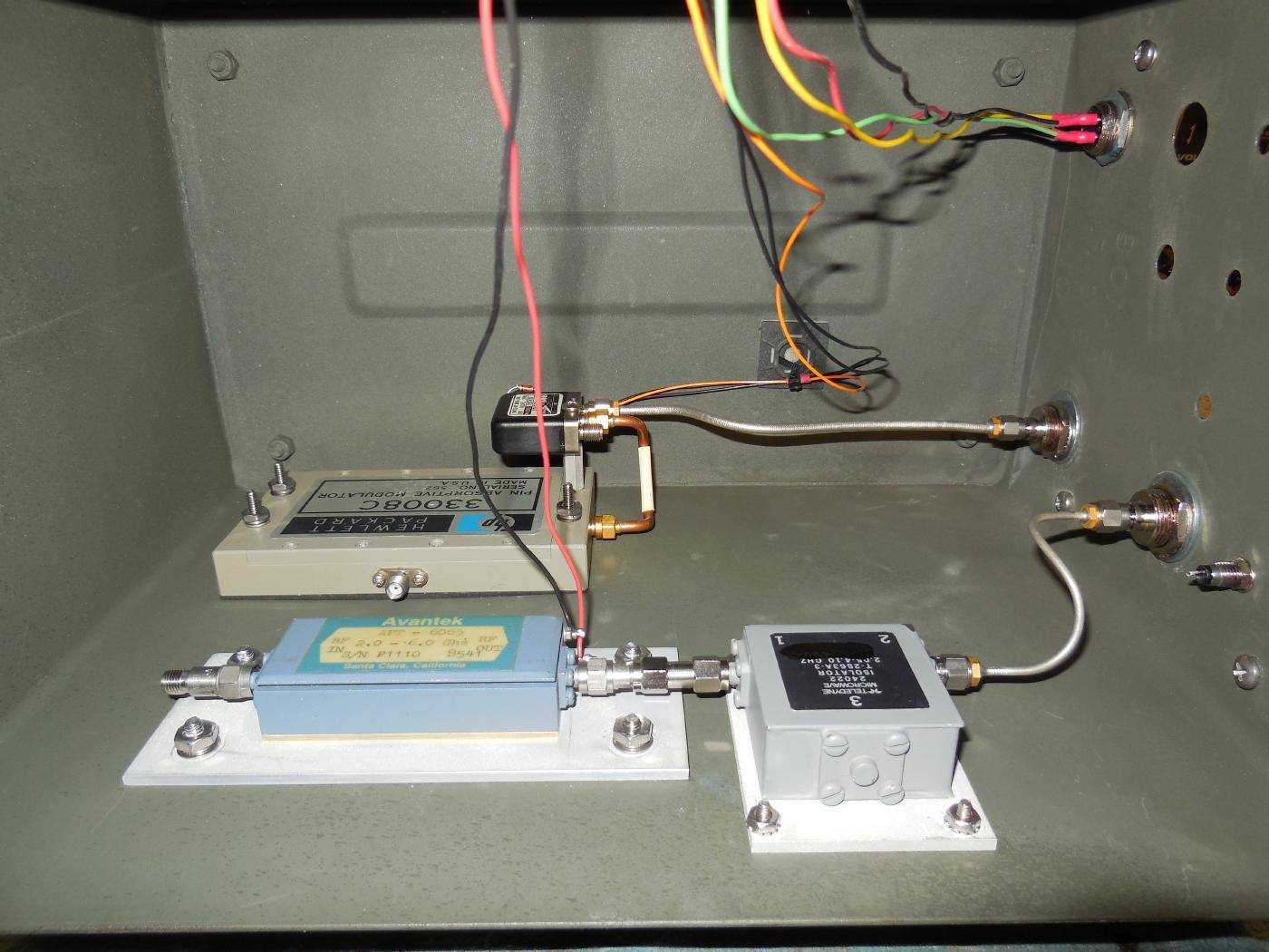
Internal overview of the (partially) completed GBPPR PHOTOANGLO transmitter unit.
The aluminum plate with the YIG oscillator and its control/voltage regulator board are mounted to the side of the case via standoffs.
Regular coaxial cables are used for some of the RF connections due to testing purposes. These will be replaced with RG-402 or RG-405 conformable coax for better isolation in the future.
A 12 to 15 dB attenuator may need to be added to the input of Avantek APT-6065 to meet its input RF power (-8 dBm) requirement. This may vary in your own design.
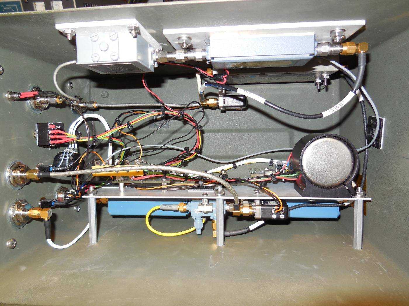
Alternate internal overview.
The FREQ TUNE 50 kohm potentiometer is a high-quality, 10-turn type with a turns counter.
An optional 4DPDT switch was added to act as a power switch for the +/-15 & +28 VDC supplies.
Pinout for the optional 8-pin AUX CONTROL auxiliary control port:
Pin      Description
1        Transmit Output Select (Ground to enable TX2 Output)
2        External Oscillator Select (Ground to enable External Oscillator Input)
3        PIN Modulator Bias & Modulation
8        Ground (Common)
Pinout for the 4-pin TX POWER external DC power input jack:
Pin      Description
1        +28 VDC Input
2        +15 VDC Input
3        -15 VDC Input
4        Ground (Common)
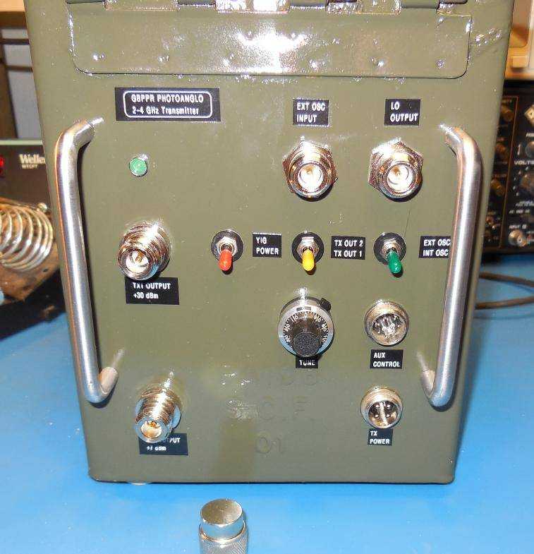
Finished front-panel overview of the GBPPR PHOTOANGLO 2-4 GHz Transmitter.
The N jack on the upper-right is the approximately +15 dBm LO OUTPUT (Local Oscillator Output) which will go to the PHOTOANGLO receiver unit. The N jack next to it is for the optional EXT OSC INPUT (External Oscillator Input, +15 dBm MAX).
The N jack on the center-left is the main +30 dBm TX1 OUTPUT (Transmit 1 Output) from the Avantek APT-6065 amplifier. The N jack below that is the +7 dBm TX2 OUTPUT (Transmit 2 Output) and should have a 50 ohm load on it. This is could also be handy for shutting down the transmitter RF output without having to power down the entire unit.
The red YIG POWER switch is to controls the +/-15 & +28 VDC input power supplies. The yellow TX OUT 2 / TX OUT 1 switch controls the transmitter output select RF relay. TX OUT 1 is the default. The green EXT OSC / INT OSC switch controls the external/internal oscillator select RF relay. INT OSC is the default.
Below the yellow switch is the FREQ TUNE multiturn potentiometer with a turns counter. Next to it is the 8-pin AUX CONTROL input jack.
Below the AUX CONTROL is the 4-pin TX POWER jack which goes to the GBPPR PHOTOANGLO TX/RX Power Supply.
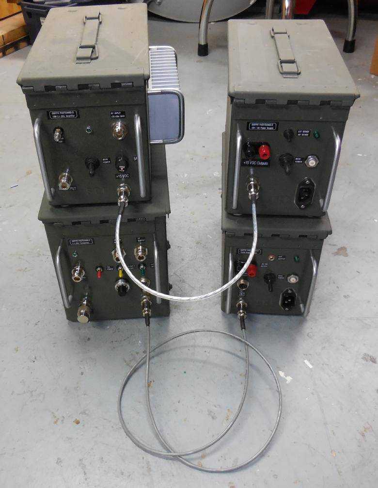
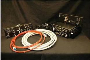
GBPPR PHOTOANGLO 2.4 GHz Transmitter with the matching GBPPR PHOTOANGLO TX/RX Power Supply (bottom).
GBPPR PHOTOANGLO 10W 2.4 GHz Amplifier with the matching GBPPR PHOTOANGLO 15V / 3A Power Supply (top).
Below is a chart of the transmitter's frequency versus RF output power (from the Avantek APT-6065). The roll-off above 4 GHz has to due with the isolator on the output of the APT-6065 amplifier.
Frequency (MHz)   RF Input (dBm)       RF Output (dBm)
2000              -8.0                 +29.1
2100              -8.1                 +29.1
2200              -8.1                 +29.3
2300              -8.2                 +30.2
2400              -8.2                 +30.5
2500              -8.5                 +30.4
2600              -8.4                 +30.8
2700              -8.3                 +30.7
2800              -8.2                 +31.0
2900              -8.3                 +30.7
3000              -8.4                 +30.6
3100              -8.4                 +30.5
3200              -8.5                 +29.9
3300              -8.3                 +29.8
3400              -8.2                 +29.9
3500              -8.3                 +29.4
3600              -8.1                 +29.3
3700              -8.4                 +28.9
3800              -8.6                 +28.3
3900              -8.5                 +28.3
4000              -8.4                 +28.4
4100              -8.3                 +27.5
4200              -8.6                 +27.3
4300              -8.5                 +24.4
4400              -8.2                 +24.1


