| van Eck-style Radiation Interception Experiments |
Overview
Back in 1985, Wim van Eck wrote two papers entitled Electromagnetic Radiation from Video Display Units: An Eavesdropping Risk? and Electromagnetic Eavesdropping Machines for Christmas? This opened the public to the fact that stray electromagnetic radiation from a computer and/or its monitor could be subject to interception and decoding by an external party. This has been known to the military and intelligence agencies since at least World War One, when it was used to help break encryption codes. The Peter Wright book Spycatcher also contains several fascinating stories from the Cold War-era on similar techniques.
There is nothing really groundbreaking about designing or implementing TEMPEST shielding to prevent such intercepts. Charlatans, petty con artists, nutcases, etc. will mention that the info is "top secret," but this is not true... You just need to know where to look :)
Also, changing your fonts won't really do that much either. If fact, you can even get this method to work without a monitor even connected!
Although far from an expert, I do understand the hardware concepts of van Eck phreaking and have also gotten it to work under "lab" conditions. The following will be a detailed explanation of a starting setup to help you in your experiments.
![[overview]](overview.png)
This is an overview of what is required to perform a van Eck-style interception. You essentially point a wideband, log-periodic directional antenna at your TARGET computer and/or monitor, amplify the recieved signal (usually the pixel clock - 28 MHz or so), then demodulate it to get a new video signal. This new video signal is then applied to a HOST monitor, while generating your own horizontal & vertical synchronization signals.
Hardware Tools
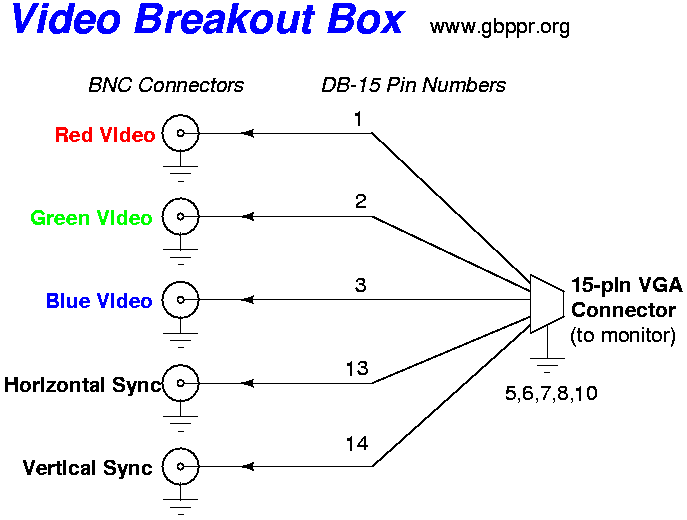
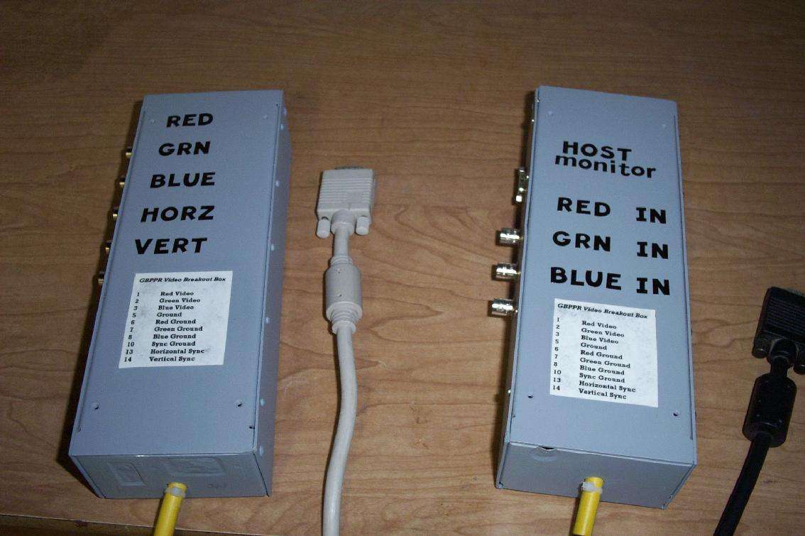
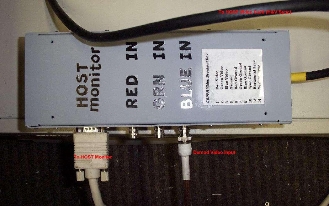
One tool you may find useful is a Video Breakout Box. This is just a standard 15-pin VGA connector with the red/green/blue video and horizontal/vertical synchronization signals running to BNC connectors. This is helpful for routing any signal you need via short BNC patch cables.
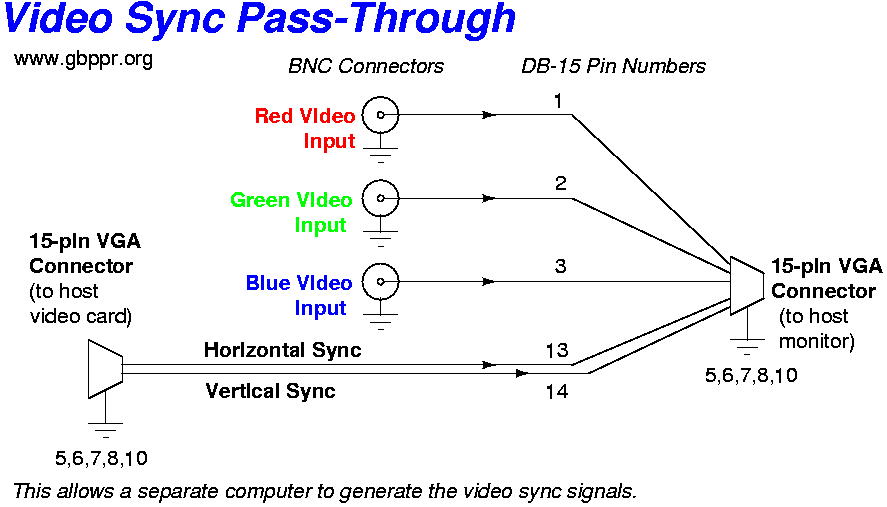
Another tool, which is mandatory, is a Video Synchronization Signal Pass-Through Box. This is required to allow a separate video card to generate the needed VGA horizontal & vertical synchronization signals. We then apply our new "intercepted" video signal on either the red, green, or blue video inputs.
Here is a picture of both the Video Breakout Box and the Video Synchronization Signal Pass-Through Box. They are built out of old Apple II power supply cases. You can salvage the needed video cables from old thrift store monitors. Note the Video Synchronization Signal Pass-Through Box has a female DB-15 jack for easily connecting the HOST monitor.
Antenna & Feedline
Spend all your money on the antenna and feedline. Seriously. Your antenna and feedline are the most important parts in a radio reciever. Use only the best possible antenna and mounting hardware and the lowest loss, highest quality feedline coax.
For your antenna, a salvaged TV reception antenna will work fairly well. Be sure to get one which will allow you to easily change polarities (horizontal to vertical), if needed. Also, be sure it has good low frequency response, down to 50 MHz or so (TV channel 2). Some antennas are for VHF/UHF only - try to avoid those.
If you do use a TV antenna, most will required a 4-to-1 transformer & balun to match to your coax (75-ohm, unbalanced). TV antennas are typically 300-ohms, balanced. We need to avoid using balanced feedline due to the interference it can receive. Your antenna will probably include a little plastic matching transformer. It may look like a little "bullet" with the words "300-to-75 ohm Matching Transformer" written on it. Throw it away!! To save a couple of pennies, manufactures avoid impedance matching properly. Here is a good example. This "matching transformer" was just a pass-through.
Here is a better 4-to-1 Matching Transformer schematic using a CoilCraft TTWB1040 surface mount, wideband transformer.
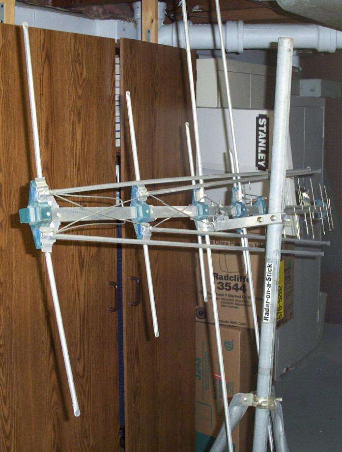
The antenna(s) used for this experimental setup where a Grove Enterprise's Scanner Beam (good but large) and a Ramsey Electronics LPY2 (poor but small).
For a proper impedance match to the antenna and the CATV distribution receive amplifiers, you'll need to use high quality 75-ohm coax. RG-6QS (quad-shield) is probably the best you'll find locally, though 1/2" 75-ohm hardline will be best for longer feedline runs. You can often get 75-ohm hardline scraps from cable TV repair people, provided they are not communist bastards - like AOL/Time Warner - then just steal it.
You probably also be forced to use F-connectors if you use RG-6QS. Stick with the higher quality ones and be sure to install them right. The center conductor shouldn't stick out too far.
Here are a couple pictures of my antenna setups, the Grove Scanner Beam (too big to be fully expanded) and the little Ramsey LPY2 (wrong frequency range).
Receive Amplifers
Not just any RF amplifier can be used for reception. Only wideband, fairly low-noise, and high dynamic range amplifiers will work. Fortunately, these already exist in the form of cable TV (CATV) distribution amplifiers. These exist to help overcome the losses from long coax runs, so they are cheap and easy to find. Like always, the quality will vary. The best possible source is the actual CATV distribution amplifiers that the cable TV company uses. These can often be had by digging through the dumpster behind your local cable TV company office, or if it's those commies at AOL/Time Warner - just steal them from the poles (those little silver boxes with hardline going in-and-out).
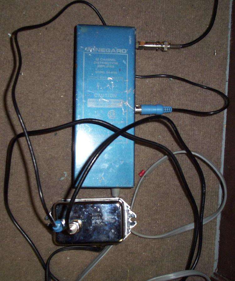
For this setup, a Winegard DA-8150 82-Channel Distribution Amplifier is used feeding a generic "V-26274" amplifier. Each has around 17 dB of gain at VHF frequencies. Both also have 75-ohm input and output impedances.
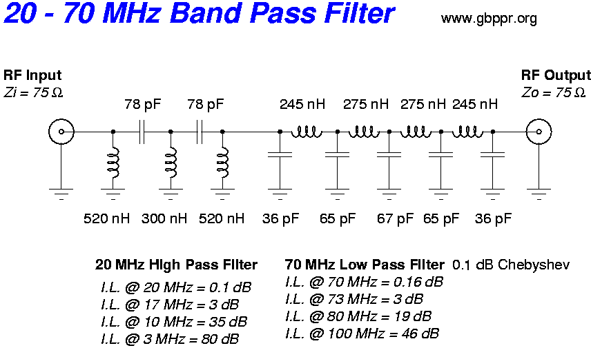
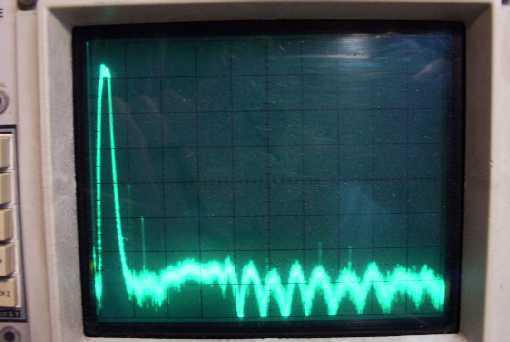
Here is a 20 - 70 MHz Band Pass Filter schematic. Experiment with different front-end filters on the receive amplifers to limit their exposure to interference from AM/FM/TV broadcast stations. A tracking generator plot of a homebrew 40 - 70 MHz band pass filter, similar to the above 20 - 70 MHz filter schematic. Yes, I made the tracking generator also, its output is relative - and not calibrated.
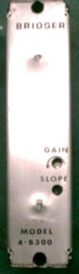
This is a commercial CATV distribution amplifier which was used with good results:
Bridger - Model 4-B300 - Picture 1 40 dB of gain from 40 - 400 MHz
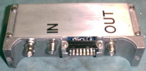
Bridger - Model 4-B300 - Picture 2 Replaced the F connectors with BNC connectors. Voltage requirements are +24 VDC at around 500 mA.
Bridger - Model 4-B300 - Picture 3 Internal view. Yellow core inductor is part of the output bias-T.
I don't know who the manufacture is, but it was probably built during the 1980s and uses the TRW CA2201 and CA623 hybird modules for amplification. Its outside case is labelled "BRIDGER" and "MODEL 4-B300". There are adjustable potentiometers for both gain and slope. Leave the slope adjustment alone, unless you know what you are doing. The only modifications made was replacing the original push-on F connectors with BNCs, adding a voltage "bias-T" to allow DC to be placed on the coaxial output for external power, replacing some of the old leaded capacitors with new surface mount versions and an overall cleanup for the circuit board.
The output voltage bias-T is made using a 1000 pF/50 VDC ceramic capacitor in series with the output RF connector. A 30 µH ferrite inductor then connects from the output RF connector to the postive power line. Be sure the capacitor and the inductor can carry the fairly high voltage and current.
Video Demodulation
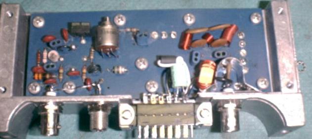
A quick-and-dirty hack to demodulate the received RF signal is to use a cable TV tuner which gives baseband video output. For this setup, a slightly modified Olson Technology OTD-3000. The frequency synthesizer was removed and a manual tuning 100 k potentiometer was added, along with a 36-volt tuning range. This allows for quickly scanning the bands and easier, manual frequency adjustment. I also tapped the divide-by-64 prescaler output so I can verify the exact local oscillator frequency with a Radio Shack frequency counter.
Example:
Prescaler output frequency is 1.651 MHz. Multiply this by 64 to get 105.664 MHz. Then subtract the 45.75 MHz IF offset to get a final receive frequency of 59.914 MHz.
The new OTD-3000 tuning ranges are as follows:
Band Switch
1	2	3	Prescaler Output (MHz)		Tuning Range (MHz)

1	1	1	1.36 -                          42 -
1	1	1	2.26                            99        (VHF Low)

0	1	1	1.97 -                          81 -
0	1	1	4.09                            216       (VHF Mid)

1	0	1	3.05 -                          150 -
1	0	1	6.57                            375       (VHF High)

1	1	0	6.06 -                          342 -
1	1	0	13.48				817       (UHF)
Here is Chapter 17 (1 M PDF) of the book Standard Handbook of Video and Television Engineering. It covers television reception and tuner functions in detail.
Spectrum Analyzer
A RF spectrum analyzer is very useful for determining the frequency of any electromagnetic radiation from your computer. This tool displays an entire frequency range in one view and will allow you to "zoom" in on a particular frequency for further scrutiny.
Yes, I built my own 0 - 1000 MHz Spectrum Analyzer. If you are up to a challange, build Scotty's Spectrum Analyzer. It's DDS/computer controlled - very nice.
HOST Computer
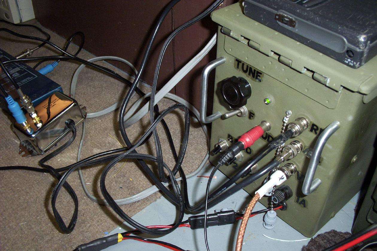
We are now ready to piece everything together. Here is a picture of my demodulation setup (front panel close up). The ammo box to the lower right contains a 12-volt lead acid battery, and the speaker is connected to the audio output jack of the OTD-3000. This is helpful for verifying TV or FM broadcast interference. Note the frequency counter reading 1.651 MHz. This equals a received frequency of 59.914 MHz. It was probably receiving the second harmonic of the pixel clock, for my TARGET monitor, which is around 28 MHz. The OTD-3000 is unable to tune below 42 MHz.
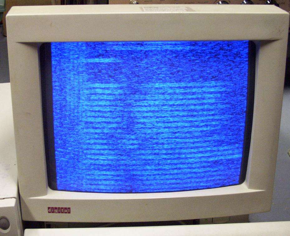
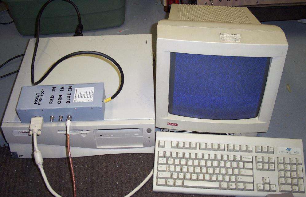
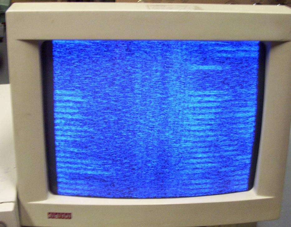
This is the display on the HOST computer monitor, a 15" original DEC C10E monitor. In the picture, it's displaying random noise from the OTD-3000 video output going to the monitor's blue video input. I used the blue video input 'cuz it looks pretty.
The computer to the left, a Compaq DP4000 with a Matrox Mystique PCI video card, is generating the horizontal & vertical synchronization signals. The operating system is RedHat 9, and the computer is in command line mode running the vgaset command.
Here is a close up picture of the Video Synchronization Signal Pass-Through Box in operation.
The specifications for the HOST computer's monitor are:
  Vertical Sync = 70.216 Hz
Horizontal Sync = 31.527 kHz
    Pixel Clock = 28.38 MHz
Those are found via the clockprobe command.
TARGET Computer
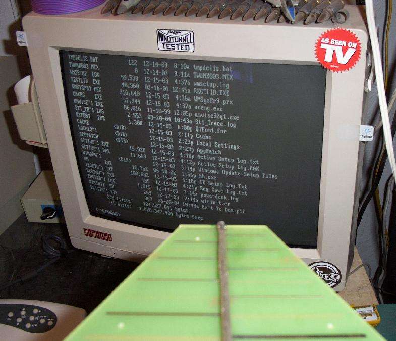
This is the display on my TARGET monitor. It's a 17" CTX 1765 with a Matrox Mystique PCI video card (Compaq DP4000). The computer was in DOS-mode, with a DIR of the C:\WINDOWS directory. The receive antenna was resting on top of the monitor, so much for the reading-your-monitor-from-miles-away-myth.
I don't know the TARGET computer's monitor specifications because Microsoft is run by freakin' retards.
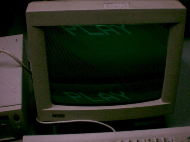
It Works!!!
Sort of.
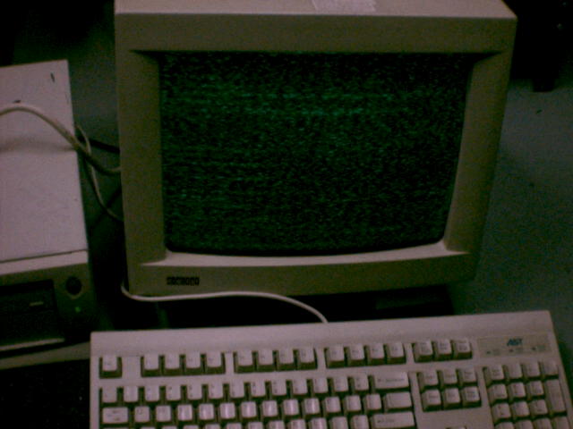
You can see the results here. The text was was actually a little crisper than the picture shows, but just barely readable. The monitor's picture is "rolling" from right-to-left because the horizontal synchronization signals were not matched prefectly. This resulted in the picture being "smeared." Here is another example of the horizontal rolling.
The maximum reception range I was able to achieve was only a few inches. Mind you, this is with a crappy antenna, cheap receive amplifiers, and no modification of the OTD-3000's video demodulation circuitry.
Extending the Range
The only true way to extend the range of "van Eck phreaking" is to hide the antenna, receive amplifiers and video demodulator somewhere near the target area. You then take the raw video output and transmit that, via a high power transmitter back to your hidden receiver location. A 20 Watt amplifier and good antennas will easily go 10 miles in the 1.2 GHz amateur radio band. To receive (and demodulate) this signal, you only need an old C-band satellite tuner, without the block downconverter.
There is an article on the construction of a homebrew 1.2 GHz ATV Video Transmitter and the amplifiers which will work for this method. The Ramsey LPY2 antenna will work very well as the 1.2 GHz transmit and receive antenna. Be sure to keep your antenna feedline cable (LMR-400 or RG-8) runs as short as possible.
It also appears possible to record the raw demodulated video signal to tape via a standard VHS VCR. Most VCRs need to see the proper sync signals before they'll start recording, but my experiments showed this is not always the case. The only major problem is the VCR will try to "fix" the signal by adding its own sync signals. This will distort the signal as needed.
Pictures from the VCR record experiment. VCR was a Sharp VC-A303U piece of junk:
VCR Record Experiment - Picture 1 Output video signal from VCR. The HOST VGA monitor and the VCR use different sync rates, hence the distortion.
VCR Record Experiment - Picture 2 Intercepted text via the radiation from the TARGET monitor - the quality is very poor.
Transmitting Video Signals
To re-create a TARGET's video signal exactly, without any noise interference, you'll need to transmit the raw video signal to a remote location. This isn't as hard as it sounds, and it is covered under this section, GBPPR VGA Video Monitor Transmitter.
The only real problem is generating the exact synchronization signals.
Software Tools
There are several useful console tools included in the SVGATextMode package. These include grabmode, which probes your monitor's current "Modeline", clockprobe, which grabs your monitor's current synchronization rates and pixel clock frequency, and vgaset, which allows you to manually tweak the horizontal and vertical synchronization rates.
Documentation for the grabmode/clockprobe commands.
Precompiled binaries for Linux/RedHat 9.0 : grabmode and clockprobe
The Estimated pixel clock value (in MHz) which is displayed by running clockprobe on your TARGET monitor should be used as the starting point for tuning your receiver.
Documentation for the vgaset command.
Precompiled binary for Linux/RedHat 9.0 : vgaset
For X11, use the included xvidtune utility.
Another tool which is useful for directly controlling VGA video card registers is setVGAreg. To read the registers use getVGAreg.
Documentation for the setVGAreg/getVGAreg commands.
Precompiled binaries for Linux/RedHat 9.0 : setVGAreg and getVGAreg
National Security Agency TEMPEST Notes / Military Guidelines
Mirror of Cryptome's National Security Agency TEMPEST program files and notes. Broken URLs and images have been fixed or noted. (Raw Index)
- NACSIM 5000 TEMPEST Fundamentals
- NSA Specification No. 94-106 Specification for Shielded Enclosures
- NACSEM 5112 NONSTOP Evaluation Techniques
- NSTISSI No. 7000 TEMPEST Countermeasures for Facilities
- NSTISSAM TEMPEST/2-95 Red/Black Installation Guidance
- NSTISSAM TEMPEST/1-92 Table of Contents and Sections 1-5
- NSTISSAM TEMPEST/1-92 Sections 6-12
- NSTISSAM TEMPEST/1-92 Appendix A (TEMPEST Overview)
- NSTISSAM TEMPEST/1-92 Appendixes B-M
- NSTISSAM TEMPEST/1-92 Distribution List
- NSA/CSS Regulation 90-6 Technical Security Program
- NSA Zoned Equipment Products Program
- NSA Endorsed TEMPEST Products Program Procedures Package
- NSA Endorsed TEMPEST Test Services Program Test Services Procedure Package
- Emissions from Bank Computer Systems Make Eavesdropping Easy, Expert Says American Banker, March 26, 1985
- Eavesdropping On the Electromagnetic Emanations of Digital Equipment: The Laws of Canada, England and the United States by Christopher J. Seline, 1989
- The Tempest over Leaking Computers by Harold Joseph Highland
- Physical Security Requirements for NSA/CSS Sensitive Compartmented Information Facilities
- TEMPEST Glossary
- US Air Force Emission Security Countermeasure Reviews
- US Air Force EI TEMPEST Installation Handbook (343k PDF)
- US Air Force Emission Security Assessments
- Radio Frequency Shielded Enclosures (MIL-HDBK-1195) (PDF Version)
- TEMPEST Shielded Facilities Chapter 12 of EP 1110-3-2 (1.2 M PDF) (Complete Document)
- U.S. Air Force Engineering Technical Letter 90-3 TEMPEST Protection for Facilities (148k PDF)
- Emission Security (EMSEC) Information Guide
- Remote Video Eavesdropping Using a Software-Defined Radio Platform by Martin Marinov (25M PDF)
- Navy INFOSEC TEMPEST Training Information
- TEMPEST Timeline
Your Tax Dollars vs. Stuff I Found at a Hamfest
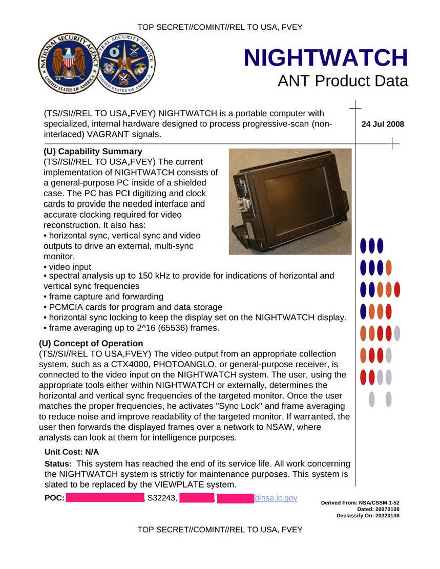
- CTX4000/PHOTOANGLO NSA's CW radar illuminator (1-4 GHz) used for VAGRANT and DROPMIRE collection.
- RAGEMASTER NSA's RF retro-reflector that provides an enhanced radar cross-section for VAGRANT collection.
- LOUDAUTO NSA's audio-based RF retro-reflector.
- NIGHTWATCH NSA's display and horizontal/vertical sync generator for processing VAGRANT signals.
- TAWDRYYARD NSA's beacon RF retro-reflector to provide rough positional location.
Notes & Links
- TEMPEST Attacks Against AES Covertly stealing keys for €200.
- TEMPEST Workshop Presentation Riga (October 2008)
- Hackers Can Wirelessly Watch Your Display by HDMI Radiation A newly discovered technique combines wireless EM monitoring and AI algorithms to "read" text on a victim's screen via HDMI radiation, and it's already being used in the wild.
- TEMPEST: Como nos vigilan?, Como "vigilar?" Article from Issue 21 of SET magazine.
- Compromising Emanations: Eavesdropping Risks of Computer Displays by Markus Kuhn (8.3M PDF)
- TEMPEST 101 by James M. Atkinson of the Granite Island Group.
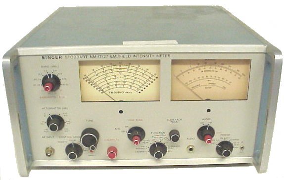
- Fair Radio Sells the Singer Model NM-17/27 wideband RFI receivers.
- Computer Monitor Specification Database
- Monitor Timing How-To From the SVGATextMode utility.
- Joel McNamara's Complete, Unofficial TEMPEST Information Page
- Signal Processing Applications for Information Extraction from the Radiation of VDUs (415k PDF)
- Information Extraction from the Radiation of VDUs by Pattern Recognition Methods (240k PDF)
- The Threat of Information Theft by Reception of Electromagnetic Radiation from RS-232 Cables by Peter Smulders (370k PDF)
- A Very Good French TEMPEST Paper (French PDF)
- The TEMPEST Method of Computer Data Interception by Al Muick
- How White Hat Hackers Stole Crypto Keys from an Offline Laptop in Another Room
- TEMPEST and EMSEC: Is it Possible to Use Electromagnetic Waves in Cyberattacks?
- van Eck TV at Makrolab
- Dynamic Sciences International Professional TEMPEST measurement receivers.
- Kaiser RAS-515A Raster Analysis System
- The LM1823: A High Quality TV Video I.F. Amplifier and Syncronous Detector for Cable Receivers (322k PDF)
- Picture of a Commercial van Eck Receiver Manufacture unknown.
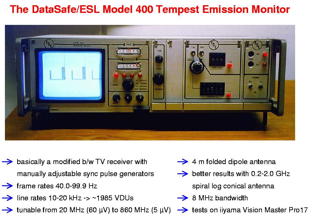
- Picture of a DataSafe/ESL Model 400 TEMPEST Emission Monitor
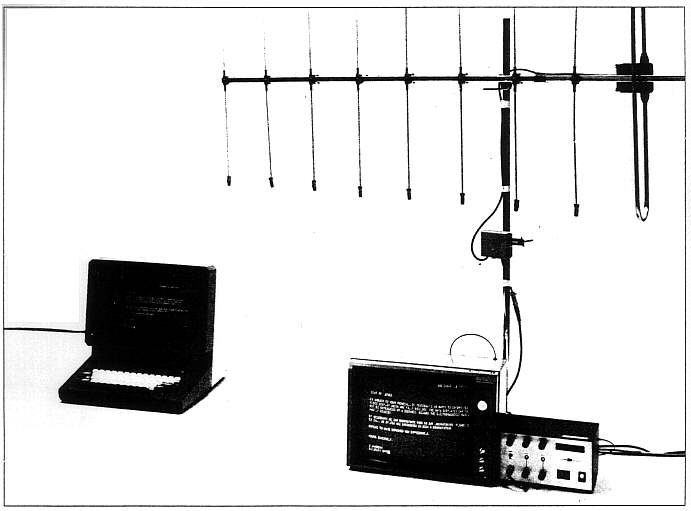
- Picture of Wim van Eck's Receiver Setup
- Picture of a Dynamic Sciences DSI-1550 TEMPEST Measurement System
- Terminal Compromise E-book novel by Winn Schwartau which involves "van Eck phreaking."
- Information Warfare E-book by Winn Schwartau. (2.0M PDF)
- ePanorama Video Circuit Links
- Siemens SITEMP Lifebook E TEMPEST-approved notebook computer.
- EMI/RFI Test Receivers by Ulrich Rohde in Ham Radio, November 1983. (150k PDF)
- A Few Things on van Eck's Method of Eavesdroping by Opticon the Disassembled - UPi
- Protective Measures Against Compromising Electro Magnetic Radiation Emitted by Video Display Terminals by Erhart Moller.
- TEMPEST Equipment from the DEFCON Website Lots of good pictures.
- TEMPEST in a Teapot by Grady Ward
- The Discovery Channel's Cyberlife with Codex CEO Frank Jones Screen captures from the interview. Note: Frank Jones is a convicted con artist.
- Nowhere to run... Nowhere to hide... The vulnerability of CRTs, CPUs, and Peripherals to TEMPEST Monitoring in the Real World by Frank Jones
- How to Build a Benchtop TEMPEST Interceptor USENET posting by Frank Jones.
- A Modern Receiving System Approach to EMI/EMC/TEMPEST Measurements (761k PDF)
- EMC/TEMPEST Detection Systems (786k PDF)
- TEMPEST Compromising Emanations Hakin9 Magazine article from 2005. (4.4M PDF)
- Keyboard Acoustic Emanations Revisited Decode keystrokes via their audio signals. (358k PDF)
- Sniffing Keystrokes via Laser and Keyboard Power
- Micro-Tel VDA-60 Video Display Analyzer - Photos & Notes
- Attenuation Measurements for Enclosures, Electromagnetic Shielding, for Electronic Test Purposes, Method of (MIL-STD-285) (535k PDF)
- Requirements for the Control of Electromagnetic Interference Characteristics of Subsystems and Equipment (MIL-STD-461E) (993k PDF)
- Grounding, Bonding, and Shielding for Common Long Haul and Tactical Communications Systems (MIL-STD-188-124B) (3.8M PDF)
- Red/Black Engineering - Installation Guidelines (MIL-HDBK-232A) (11.2M PDF)
- NSA TEMPEST Level 1 Manufactures
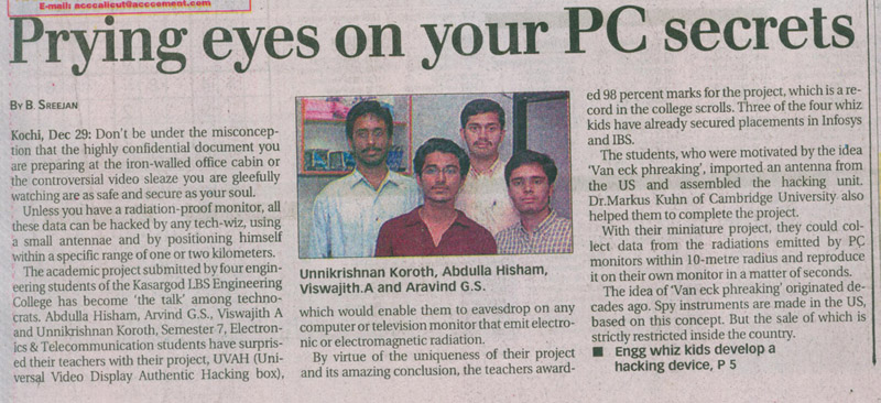
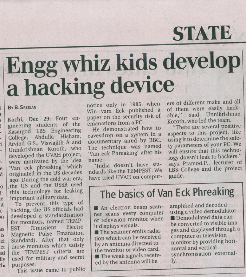
- Prying Eyes on Your PC Newspaper article from India. (Part 2: Whiz Kids Develop a Hacking Device)
- van Eck Devices
- Rise of the TEMPEST by Sarah Ellerman (Mirror)
- Coming to a Desktop Near You: TEMPEST Capabilities
- Laptops and Flat Panels Now Vulnerable to van Eck Methods
- CRT Eavesdropping: Optical TEMPEST
- Who's Listening by Captain Zap (Ian Murphy). From P/HUN Issue #3, Volume 2.
- Video Eavesdropping Demo at CeBIT 2006
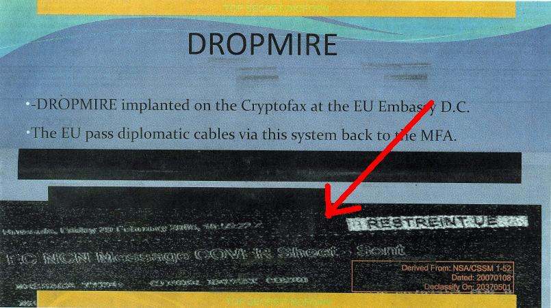
- Eavesdropping a Fax Machine Example results from a NSA DROPMIRE passive collection of electromagnetic emanations from a secure fax machine.
- van Eck Radiation Helps Catch Spies RISKS Digest 15.59
- Wang's ZONE Program An alternate TEMPEST countermeasure.
- Wang Government Services, Inc. Secure systems product overview.
- Beyond van Eck Phreaking by John J. Williams
- Early "van Eck Radiation" Information by Tim Johnson
- Soft TEMPEST: Hidden Data Transmission Using Electromagnetic Emanations (477k PDF) (Slides)
- The Impact of Electromagnetic Radiation Considerations on Computer System Architecture by Carlo Kopp and Ronald Pose. (103k PDF)
- Private Circuits: Securing Hardware Against Probing Attacks by Yuval Ishai, Amit Sahai, and David Wagner. (230k PDF)
- Information Leakage from Optical Emanations by Joe Loughry and David A. Umphress (354k PDF)
- Is TEMPEST a Threat or Hoax? by Lorna Collier for SmartComputing. (180k PDF) (HTML Version)
- TEMPEST, Conspiracy Theories and Tinfoil Dreams by Chris Gates
- Japanese TEMPEST Information
- The Tempest Surrounding TEMPEST by Arik Hesseldahl
- TEMPEST Brewing for PC Privacy?
- TEMPEST Notes by Phil Karn, (KA9Q)
- Seeing Through Walls Most of this "new" technology is over 40 years old.
- DEFCON Forums Thread on van Eck Phreaking
- Stephen Hawking is a F*cking Crybaby Funny story envolving van Eck phreaking.
- Declassified NSA Document Reveals the Secret History of TEMPEST
- TEMPEST: A Signal Problem Official TEMPEST document from the NSA. Censorship of the RF flooding technique. (285k PDF)
- Data Interception Through Electromagnetic Emanation Monitoring by Christopher Peskin. (1M PDF)
- Eavesdrop on Keyboards Wirelessly (Hack a Day Entry)
- TEMPEST: A Signal Problem From Hack a Day.
- Exposing Computer Monitor Side-Channel Vulnerabilities With TempestSDR From Hack a Day.
- TEMPEST Comes to GNU Radio From Hack a Day.
- Keyboard Sniffers to Steal Data
- Schneier on Security: The Discovery of TEMPEST
- New-Wave Spies Electronic eavesdropping is becoming mere child's play. (Text Grab)
- van Eck Phreaking Caution: Wikipedia
- TEMPEST Caution: Wikipedia
- Sniffing Keystrokes via Laser and Keyboard Power
- How Hackers Can Steal Secrets from Reflections
- How to Steal an Encryption Key With a $20 Software Defined Radio and $200 of Parts The cost of "Van Eck phreaking" has dramatically dropped. The side-channel attack used to monitor every word you type - by eavesdropping on the...
- Beating the TEMPEST
- DVI (HDMI) and DisplayPort Digital Video Interfaces in Electromagnetic Eavesdropping Process (1.1M PDF)
- Snooping Through the Power Socket
- Acoustic Surveillance of Physically Unmodified PCs (876k PDF)
- So, You Think You're Secure? by Mr. Zippy! in The Infinity Concept, Issue #2.
- vanecker2600's Flickr Photostream Photos of what appears to be some type of "van Eck" device, or just an Icom R3.
- van Eck Phreak Links & Notes by Jon Grover
- U.S. Army Regulation 381-14: Technical Surveillance Countermeasures From November 1986. (2.5M PDF)
- Televisions, Video Privacy, and Powerline Electromagnetic Interference (665k PDF)
- Play Along With NSA: The RAFTER Unintentional Radio Emissions How-To
- New TrojPix Attack Leaks Data From Air-Gapped Systems via Video Cable Emissions
Related Audio/Video
- TEMPEST - BBC Report on Van Eck Phreaking Here is an old report from the BBC on "Van Eck Phreaking," a method of computer eavesdropping. (YouTube) (WebM)
- TEMPEST HDMI Demo A HDMI/DVI connected monitor is viewed remotely via radio emanations, by Windytan
- What is the software? - It's something that I made myself for this purpose. (GRCon20 - SDR Analog Video Decoding Adventures
- Can you publish the software? - Unfortunately not, but there is a similar open source program publicly available, called TempestSDR. Check out gr-tempest too!
- Can you sell the software? - No - I can't legally guarantee that there is absolutely no components from sources that have incompatible licensing.
- How can a radio signal be made into a picture? - 1.) Tune the radio into the correct frequency. 2.) Set it to sample I/Q at 10 million samples per second or more. 3.) Take the signal amplitude at every sample (sqrt(i*i + q*q)) and directly use it as the brightness of a pixel. 4) Plot this pixel into an image. Then, move to the next pixel to the right. If it's the last pixel of the row, move to the next row. 5) There is a synchronization pulse readily available in every row of pixels; this can be used to line up the rows. You can use a PLL to lock onto it. 6) How many pixels in a row? This has to be determined experimentally in a case-by-case basis.
- Which receiver is this? - AirSpy R2
- What is the big antenna? - It's a 430-470 MHz 5-el +9.7 dB Yagi-Uda, an old telco test antenna that someone gave away for free.
- What do I need to accomplish this? Google for "tempest hackaday", there is an open-source solution available.
- Why is this signal being emanated? - Bit transitions in the HDMI data cause changes in the electromagnetic field that are concentrated on multiples of the pixel clock frequency and emanated as radio waves. The cable is most likely acting as an antenna.
- What can be done to prevent this? - Use a shorter cable, or a scrambled protocol such as HDMI2 or DisplayPort. Scrambling makes it very difficult to recover picture information.
- HDMI RFI Clock 148.35/148.5/296.7/297/445.5/742.5/445.05 MHz
- Rohde & Schwarz Demonstrates TEMPEST Receiver Rohde & Schwarz demonstrates their new TEMPEST receiver allowing testing to the specification to meet gov't EMI levels at EMC SI/PI 2019. (YouTube)
- All Your Keyboards Are Belong To Us! Federico Lucifredi at DEFCON 33
- GRCon21 - gr-tempest: Spying Video Interfaces Through Electromagnetic Emanations Like all time-varying voltage and current, a video interface connecting a PC to its monitor emits electromagnetic waves. The attack commonly known as TEMPEST (or Van Eck Phreaking) consists in receiving this signal and inferring the image being displayed on the monitor; that is to say, pointing an antenna to a PC and spying the monitor. This is a particularly interesting application for Software Defined Radio, as it requires modeling the signal and implementing a custom receiver. (YouTube)
- TechNet Indo-Pacific-Hawaii: NSA TEMPEST & Hardware Hardened Against Electromagnetic Emissions SecureNinjaTV is back to traveling far and wide to look for interesting aspects of cybersecurity - this time we're in Honolulu, Hawaii to discuss the TEMPEST Certification Program and certified hardware with Andrew Burke from CIS Secure. (YouTube)
- Hacking Your Monitor With RTL-SDR Let's see how to use TempestSDR with RTL-SDR! (YouTube)
- Eavesdropping Video Monitors with TempestSDR RTL-SDR How to eavesdrop on video monitors using an SDR receiver along with TempestSDR software. Supports Airspy, RTL-SDR, SDRPlay, HackRF. (YouTube)
- gr-tempest: Spying Video Interfaces Through Electromagnetic Emanations
- Dark Tip: van Eck Phreaking Kevin Rose segment from The Screensavers. (YouTube)
- Voting Computer TEMPEST Attack (YouTube)
- CRT Radio Frequency (YouTube)
- van Eck Video Monitoring System Demonstration (YouTube)
- Japanese TEMPEST Demonstration This video clip demonstrates tests carried out in Japan (NHK) on the vulnerability of standard office equipment to eavesdropping. (YouTube)
- TEMPEST - Protection from Computer Eavesdropping This is a dated BBC Tomorrow's World production, that demonstrated the ease in which computers could be hacked. (YouTube)
- TEMPEST Keyboard Eavesdropping Carried Out by a Security and Cryptography Lab in Switzerland (YouTube)
- Overview of TEMPEST and van Eck Shielding and Radiation by Winn Schwartau at DEFCON 2. (2.3M MP3 file)
- Off The Hook, Dec. 1991 Winn Schwartau discusses his book Terminal Compromise. (6.8M MP3) (Off The Hook Archives)
- What is van Eck Phreaking?! by Reverse Engineering News
Related Patents
- Low-Cost Countermeasures Against Compromising Electromagnetic Computer Emanations U.S. Patent 6,721,423 (194k PDF)
- Antenna Shroud TEMPEST Armor U.S. Patent Number 4,965,606 (624k PDF)
- System for Protecting Digital Equipment Against Remote Access U.S. Patent 5,165,098 (368k PDF)
- Parallel Transmission to Mask Data Radiation U.S. Patent 4,932,057 (450k PDF)
- System for Preventing Remote Detection of Computer Data from TEMPEST Signal Emissions U.S. Patent 5,297,201 (700k PDF)
- Secret Radio Communication System U.S. Patent 2,476,337 (1.4M PDF)
Other Related GBPPR Projects
Return to Homebrew Military & Espionage Electronics Page